| Date: 04-09-2018 | |
| Number of Hours: 1 | |
| Manual Reference: no ref |
Time to get ready to finally build these strakes. I started with 6 prep steps and then a 10 step plan for moving things around in the workshop. I need to fit a wing to do a ‘templated’ baffle off it. I may leave it on while I do the main parts of the left strake. At least until we have to flip the fuselage.
Thanks to Darren, John, Peter and John for their time and efforts to help me get this all moved.
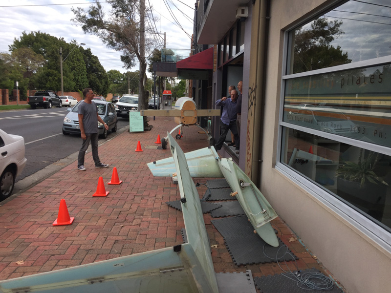
Everything had to come out first! We were careful not to obstruct the footpath and had someone ensuring any passersby were kept clear and safe. There might have been one or two that walked by. A bit of street entertainment for them. No one seems to care or have much interest really.
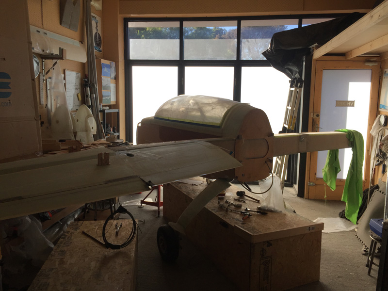
…and now there is not a lot of room for me to work inside!
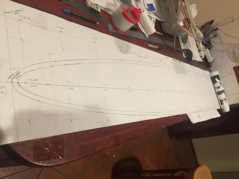
This is the master drawing for the fuselage sides of the strakes. I have already drawn this on the fuselage but I need to do it again. Both sides did not match perfectly. I might as well start out with these measurements matching on each side, a much better chance of the plane flying straight would be my viewpoint here.
If you want the strake co-ordinates that I’m using they are in this .xlsx file and its probably a good idea for my build to document this here too. XEZ Complete Strake coordinates final
I have no proof it will work. In fact I will never really know if it works and how well compared to the plans strake profiles.
I’m using a blended NACA 67 section into the plans modified Eppler 1230 wing section. We have a 14% improvement if applied to the whole strake, which it isn’t. It’s 3.5% reduction in overall drag for the whole plane at 180 knots cruise around 2 degrees nose up and I think we looked at 8000DA for the Reynolds number. This is from a computer program without any wind tunnel or full scale tests.
In reality, maybe a bit less than 3% drag reduction HA! I’d probably get that with a cut and polish and even more with a bit of tape over the wing joins. So if a plans Long-EZ has an L/D of 17:1 my plane may have an L/D of 17.5:1. Well I might be able to measure that one day although the results would have to include all the other little air-frame changes I’ve made. That said 0.5 of an L/D point is probably in the (data) noise anyway.
I caution anyone to consider carefully before playing around with this stuff. Please do not copy what I have done as the results are completely untested and unproven. It’s at your own risk if you use anything on this site of course. I’m just a guy building a plane and telling you what I have done.


