| Date: 01-24-2015 | |
| Number of Hours: 5 | |
| Manual Reference: 20-1 |
This was over two days. First up I’d now worked out the plan for my HF antenna. Yes it will be about 52 feet long! A folded dipole. This means up the wing up the winglets and back then down the wing again and joined to the same on the other side. The two loose ends get joined at the antenna tuner in the cockpit..got it?
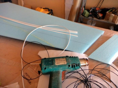
I’m using 18 AWG wire and heat shrink tube with the tube preshrunk so that the cable slides in it allowing for wing/winglet flex. You can see the cable in the tubing in pic one. Also in that shot is a bit of foam I have to join to the top of the winglet. So I first marked the out and back run on both sides of the winglet. This needs to be below the top and I just put a hole through the winglet for the return run. I used the dremel and a straight edge to cut a channel both sides for this antenna wire and then very dry micro to set the tube with the wire in place. All those pins are to ensure it stays below the surface level while curing.
A good time to also glue on the foam as the CNC cores are 1″ shorter than the plans final height or if you like they allow for the 1″ top block that is called out for.. what a waste of time. I used polyurethane glue for the foam as I usually do instead of micro. Maybe its lighter. Again I used lots of pins to keep things in place.
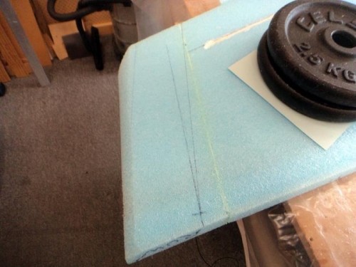
The next day after cure I removed the pins and marked out a 6 degree rake angle at the top of the winglet. This is after a LOT of research and bothering a couple of friends (sorry guys) and more research as to what I was going to do at the top here. I have lots of Boeing pics too although I will go a bit slower. Anyway a six degrees rake was the winner for that part of the winglet.
HF antenna materials
Winglet extension
Marking out the rake angle


