• Home
  • Flying
    • First Flight
  • Build by Chapter
    • Ch 3 Education
    • Ch 4 Fuselage Bulkheads
    • Ch 5 Fuselage Sides
    • Ch 6 Fuselage Assembly
    • Ch 7 Fuselage Exterior
    • Ch 8 Roll Over/Seat Belts
    • Ch 9 Main Gear/Landing Brake
    • Ch 10 Canard
    • Ch 11 Elevators
    • Ch 12 Canard Installation
    • Ch 13 Nose and Nose Gear
    • Ch 14 CenterSection Spar
    • Ch 15 Firewall and Accessories
    • Ch 16 Control System
    • Ch 17 Roll/Pitch Trim System
    • Ch 18 Canopy
    • Ch 19 Wings, Alierons
    • Ch 20 Winglets/Rudders
    • Ch 21 Strakes – Fuel/Baggage
    • Ch 22 Electrical System
    • Ch 23 Engine Installation
    • Ch 24 Covers/Consoles
    • Ch 25 Finishing
    • Ch 26 Upholstry
  • Build Mods
    • Liquid Cooling, Numbers, Weights and Flow
    • Cooling
      • Solving Ground Cooling 1
      • Solving Ground Cooling 2
      • Solving Ground Cooling 3
      • Solving Ground Cooling 4
      • Solving Ground Cooling 5
      • Solving Ground Cooling 6
      • Solving Ground Cooling7 – Test Data
      • Solving Ground Cooling 8 – Flap Building
      • Solving Ground Cooling 9 – Hinges
      • Solving Ground Cooling 10 – Lower Flaps
      • Solving Ground Cooling 11 – Upper Flaps
      • Solving Ground Cooling 12 – Completed
      • Cooling the Beast 1
      • Cooling the Beast 2 – Lower Cowl Expansion
      • Cooling the Beast 3 – KW Oil Cooler Diffuser
    • EVS (Enhanced Vision System)
    • Cowl Keeper
    • Rudder Gust Locks
    • Wing Fences
    • Post Cure
    • Hinge Upgrade
    • RAM Air & Hellhole Cover
    • Main Gear Beef Up
    • Pilot Side Windows
    • Baggage Pods
    • Winglet Intersection Fairings
    • Titanium Rollover
    • Nose Gear Doors
    • Wheel Pants/Gear Leg Fairing
    • Cabin heating System
    • Fuel System
    • Roll and Pitch Trim
    • Oxygen System
    • The Ferry Tank
    • Cruise Angle Indicator
    • Fire Extinguisher Install
  • Round the World
    • RTW Route East #12 rev1
    • Survival Equipment
    • Training Flights
  • Other Stuff
    • Blog
    • Around the World: RAAUS Sport Pilot Issue 110
    • Taxi Tests
    • Summary Feb ’24 from an SAAA Meeting
    • AOPA Pilot 27th Sept 2019
    • Build Tests
    • Flying Stories
      • A Long Easy Dream ’06
      • Townsville ’07
      • Cairns ’08
      • Albany ’08
      • East Coast ’08
      • Brisbane ’09
      • Cairns ’10
      • Perth ’10
    • Non Build Mods
      • F16 Scoop for JZE
      • Ram Air Box for JZE
      • Strange Tips
    • Milestones
    • Links
  • Contact

Blog

Home
Blog
Vortilons

Vortilons

5 years ago
Dave Berenholtz
Blog, Ch 10 Canard
Date:  08-01-2020
Number of Hours:  32
Manual Reference:  10_1 Roncz Plans

The 737-800 has three Vortilons per wing, so why wouldn’t my Long-EZ?

When the original GU canard was updated with the ‘Roncz’,  this new canard created more lift. My understanding is that this narrowed the gap between when the main wing stalled after the canard stall. To increase this gap and retain a very safe flying quality of the aircraft, the main wing efficiency was improved with these little ‘fences’.

I am making them now so that they can be painted separately and then installed after the main wings are painted. This way if they ever need to be removed, say if one was damaged, its not a repaint of the wing.

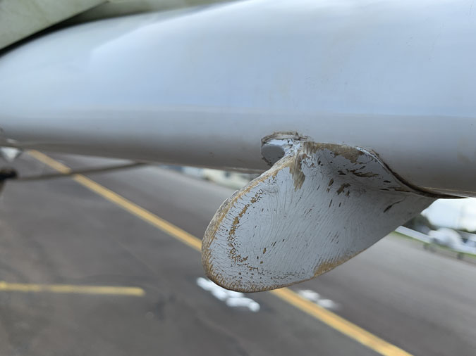
You can always tell a Long-EZ owner at the beach, that will be the person with the deep scars in their back from bumping into these things while working on the plane. This is a vortilon on my flying Long-EZ. I’m sure DNA testing on the very worn tips would detail the previous three owners …and myself.

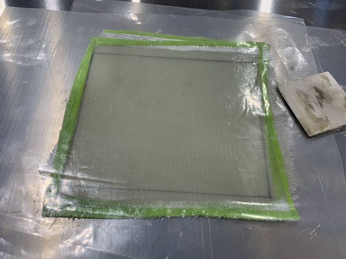
We start with 4 plies of BID at the usual 45 degree bias.

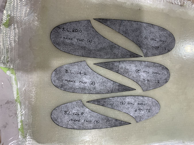
Fortunately my flying plane came with the Roncz canard plans in full size. On that plane it originally had a GU canard and the builder made another one as the upgrade came sometime after 1980. He had #74 plans so it was pretty early on.

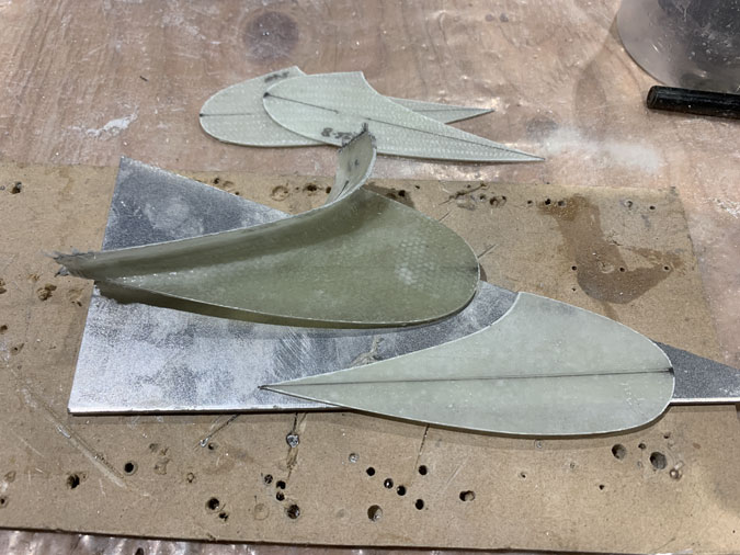
I just did a copy on my printer, cut them out and glued them onto the cured glass ready to cut out. Easy.

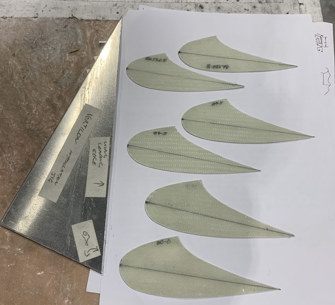
Here we are cut out. I was a bit disappointed that the center line was not drawn in on the plans. I had a go on my own. This is meant to line up with the longerons. The metal piece is a template that gets you the correct angle for installation. I used some scrape aluminium.

Their position on the wing is fortunately given as a measurement along the leading edge and very easy to set up per plans.

Oh boy, another exercise in herding cats. How are you meant to line everything up, hold it all in place and glass the things on? I got the wing set at zero degrees by realizing the winglets are at 60 degrees and so very easy to rig level.

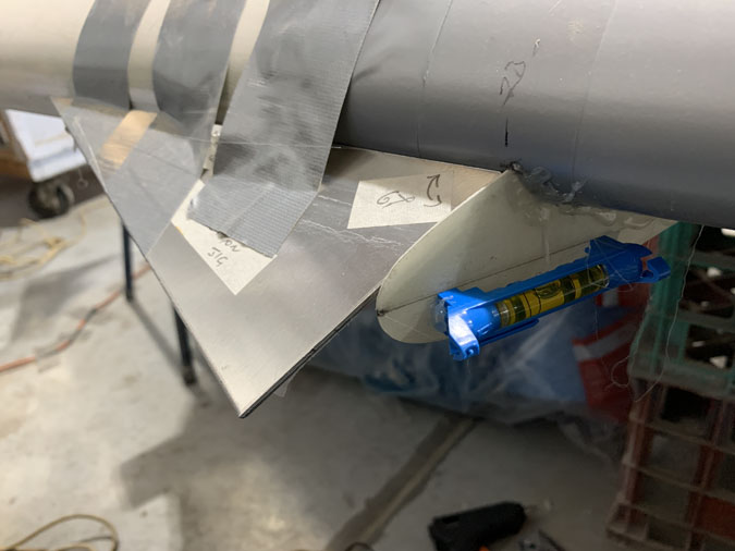
I had this idea of hot gluing the above little blue level to the centerline I’d made. Good idea but if the line is a fraction out then the bubble is WAY out, and I was really only eyeballing that line.

My process was to get that vortilon hot glued in place on one side and then glass the other. After cure I could carefully remove the glue and then do the opposite side.

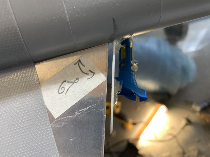
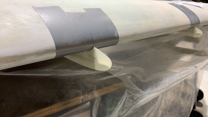
Haaaa but where is that jig going? I decided it needed to be right on the center of pressure of the wing (leading edge) and parallel to it as best I could make it. Otherwise the gap you see above would not be consistent and wouldn’t have my 67 degrees.

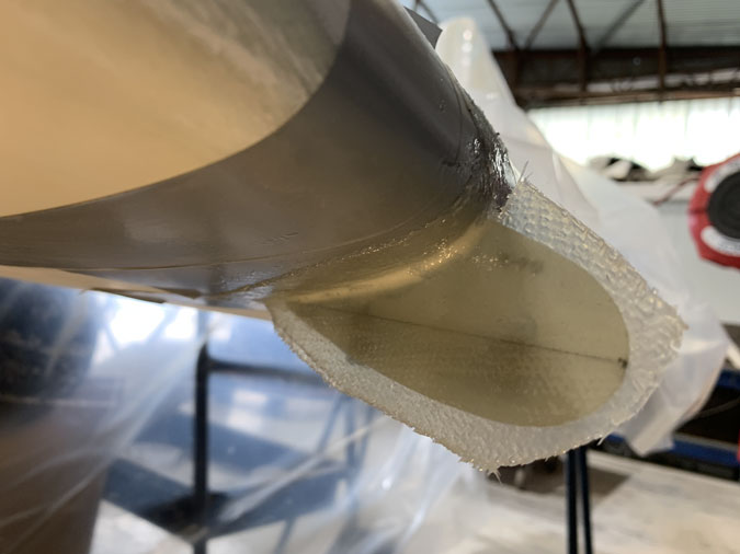
Each side gets a two ply layup to connect it. We just need .4″ on the sides for attachment.

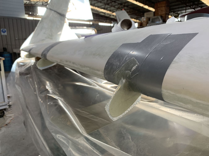
Once both sides are done its fun and games getting the thing off! Yes I used the usual grey release duct tape. As the nose wraps a little it is not as simple as you’d think.

After a bit I understood that the main thing is the angle to the wing. The angle of the vortilon relative to the longerons is perhaps less critical and maybe thats why it was not drawn in on the plans. It turns out if you have profiled your wings correctly and made the vortilons to plans they tend to sit in the right place anyway.

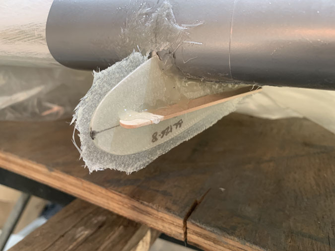
I got less anal about the waterline and found that if I used a mixing stick I would get the vortilon nice and straight. I’d made one that ended up with a bend so got to do another. <sigh>

Without the bubble level I could do three at once instead on one at a time. Much more efficient.

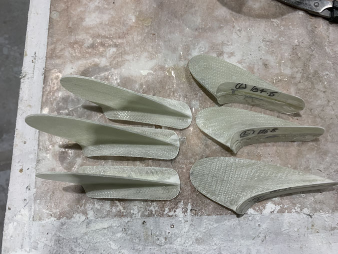
Now here’s a tip. When you make the two sets there is a left and right of course. They are not the same. You need to ensure that the 67 degree jig tool is on the correct side when you are setting them up. They can go either side on both wings!

So you might consider which way the vortilon is pointing when you make them. Otherwise you might have to make an extra set! That is all I’m saying on the matter, I make no admissions.

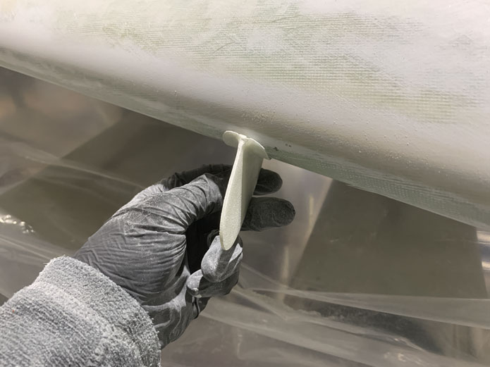
Here we have one of the six cleaned up and almost ready for paint.


Previous Post
Nose Gear Backup Battery Mounting
Next Post
Interior Painting 1

Leave a Reply Cancel reply

Your email address will not be published. Required fields are marked *

Fill out this field
Fill out this field
Please enter a valid email address.

CategoryLogsHours
All157617079
Uncategorized135
Ch 3 Education220
Ch 4 Fuselage Bulkheads25231
Ch 5 Fuselage Sides32283
Ch 6 Fuselage Assembly30270
Ch 7 Fuselage Exterior14140
Ch 8 Roll Over/Seat Belts990
Ch 9 Main Gear/Landing Brake71642
Ch 10 Canard28287
Ch 11 Elevators36298
Ch 12 Canard Installation12102
Ch 13 Nose and Nose Gear1291097
Ch 14 CenterSection Spar57525
Ch 15 Firewall and Accessories448
Ch 16 Control System27237
Ch 17 Roll/Pitch Trim System654
Ch 18 Canopy70502
Ch 19 Wings, Alierons1271090
Ch 20 Winglets/Rudders71528
Ch 21 Strakes - Fuel/Baggage65437
Ch 22 Electrical System591031
Ch 23 Engine Installation961152
Ch 24 Covers/Fairings/Consoles25202
Ch 25 Finishing561084
Ch 26 Upholstry340
Fuel System46310
Rollover1050
Cabin heating System60331
The Ferry Tank335
Blog2694182
Build Mods2252513
Nose Gear Doors856
Wheel Pants/Gear Leg Fairing40473
Oxygen System762
Roll and Pitch Trim964
Winglet Intersection Fairings445
Baggage Pods11104
Pilot Side Windows437
RAM Air & Hellhole Cover15177
Main Gear Beef Up322
Post Cure124
Fire Extinguisher16
Wing Fences13
EVS (Enhanced Visual System)130
Hinge Upgrade115
Cowl Keeper110
Rudder Gust Locks19
Cooling20607
Taxi Tests42
Flying10

Complete the Test Flight Program

2025/6/30 10:26:01

Round Australia in Four Flights

2026/4/1 10:26:01

Round the World Departure

2026/8/22 10:26:01

Rough River Flyin, Sept 23, 2026

2026/9/23 10:26:01

© Copyright 2025 Dave Berenholtz