| Date: 05-26-2019 | |
| Number of Hours: 10 | |
| Manual Reference: no ref |
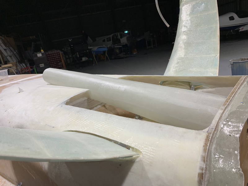
The scoop position where it ends below the level of the firewall was just not going to fly. It felt wrong, looked wrong, (although aesthetically OK) and I was having to try too hard to justify the design.
Here it is again. This is position and angle are not OK.
Out came Hoerner’s, ‘Fluid-Dynamic Drag’, the Bible for these sort of issues.
OK, so while my flush mount scoop is great for minimum drag BUT further reading tells me it is pretty poor for getting the air at the end of the scoop pressurised as I slow it down. In fact it has significant losses and so reducing the gains I was aiming to achieve by about a third. That’s not to mention that all the pictures of airplanes with various scoops ALL have them offset from the bottom of the fuselage.
How much offset was my new question? Well we want to be below the boundary layer and in free stream air. OK, so how thick is the boundary layer?
That depends on how fast you are going and how thick the air is and how far back from the tip of the nose you are. Grrrrr… This relates to a dimensionless number, a ‘Reynolds’ number (Re).
Re = speed x length / kinematic viscosity
Re = 6378 x fps x length
1 knot = 1.68781 fps 6378 x 1.68781 = 10765
say 180 knots = 10765 X 180
Re = 1,937,700
so square root is = 1392
(we are assuming sea Level for the Re)
Nose to scoop is 8’4″ or 8.33 (100″)
Delta (thickness)/distance = 5/square root of the Re (derived from experimental data many years ago)
Delta = 8.33 x 12(convert to inches) X 5/1392 = Boundary layer 0.36″
We also want to allow for different AOA’s when climbing and Density Altitude which effects the Re
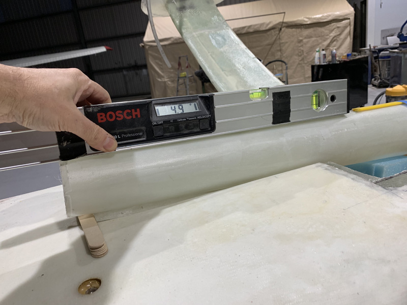
Which all makes me think .75″ to 1″ is in fact a good enough distance, even a bit more than necessary perhaps. JZE ( my flying EZ) is about 2.6 degrees nose up at 140 knots. So we are looking at 2 degrees up at 180knots at a guess. Our scoop can be that much offset from the bottom angle.
Yes 4.9 less 2 degrees = 2.9 degrees, more than ideal. I get that. In the end I opted for 0.8″ offset at the scoop entry as a sweet spot for making the angles look correct and being well below the boundary layer. The 2.9 I believe is still a reasonable compromise with all the other factors in play for angle to the relative wind.
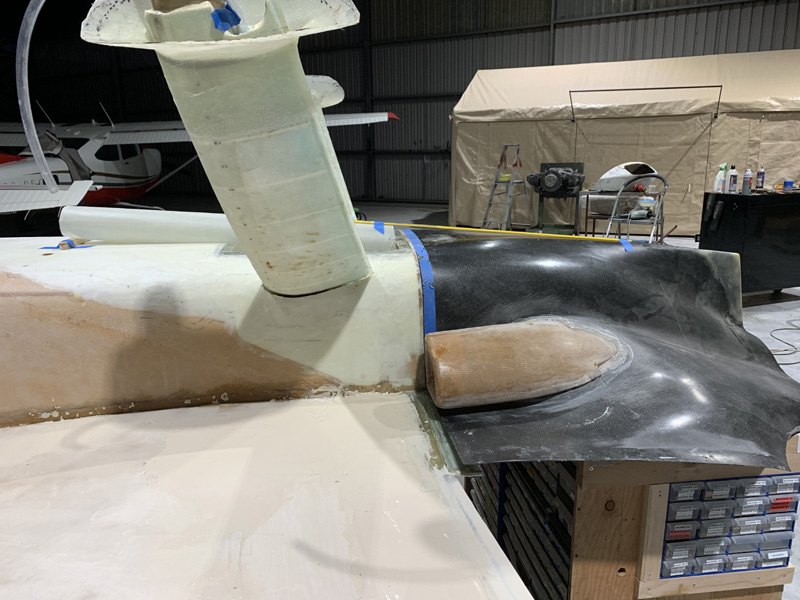
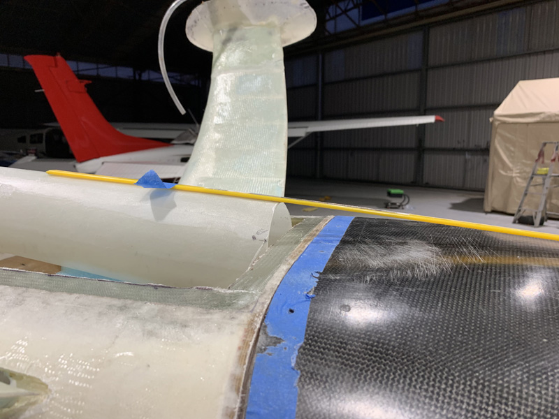
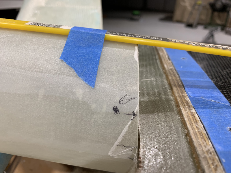
We also have to deal with the air coming off the scoop bottom onto the cowl. We need a fairing where the yellow line is marking. I also need to deal with my suddenly too short firewall!
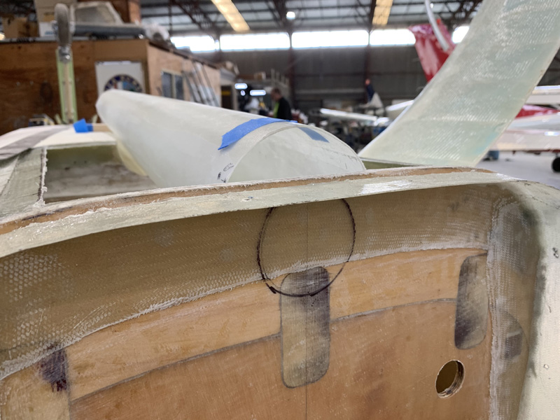
The next issue is how to hook up to my 65mm OD intake for the engine. Here you can see I’m thinking that if I get this 65mm or close to it above the line of the cowl, then I can leave the cowl bottom as it is and just add a fairing on top.
This is roughly where I plan to plumb the intake for the engine from the RAM air. Of course an air filter goes in there first.
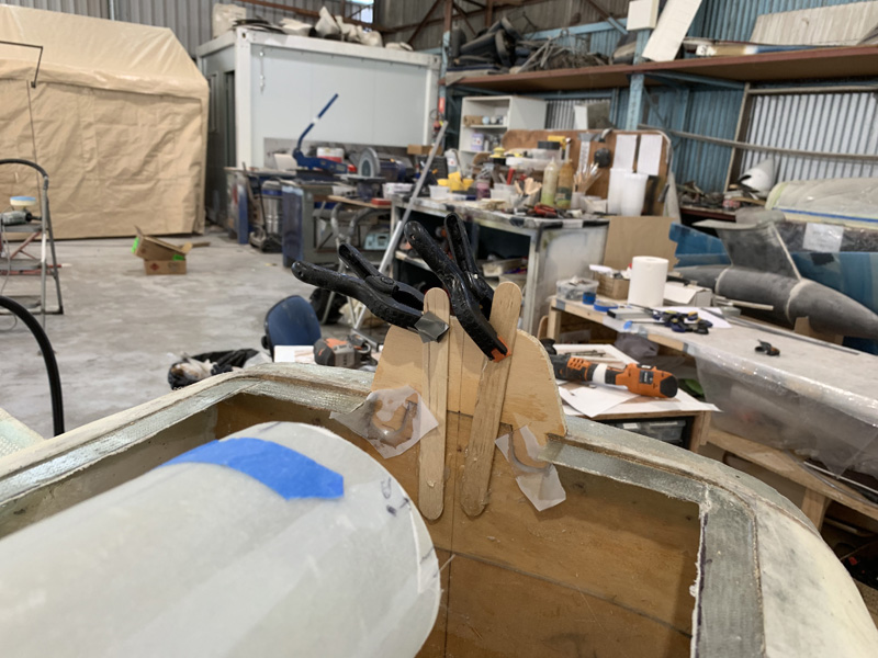
Here I’ve already (I tell myself I am fast when it is all going smoothly) added to the firewall at the bottom (top as the plane is inverted in this picture). I’m using the same marine ply and just made a piece with two fingers at the top (or bottom in the pic). I have inlaid them into the existing firewall and used epoxy as well as a few sticks to keep it in place. I will soon add glass to strengthen the bond.
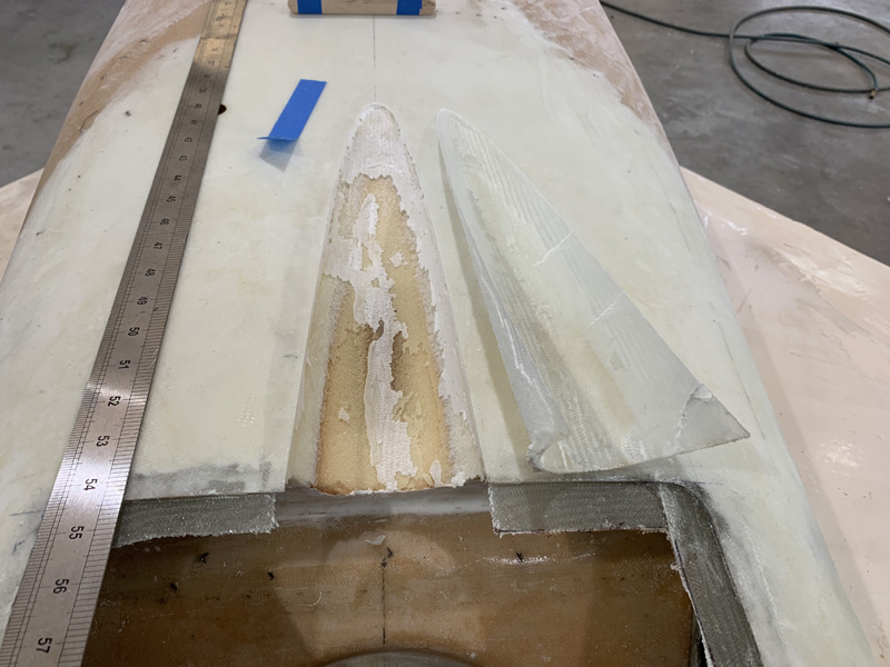
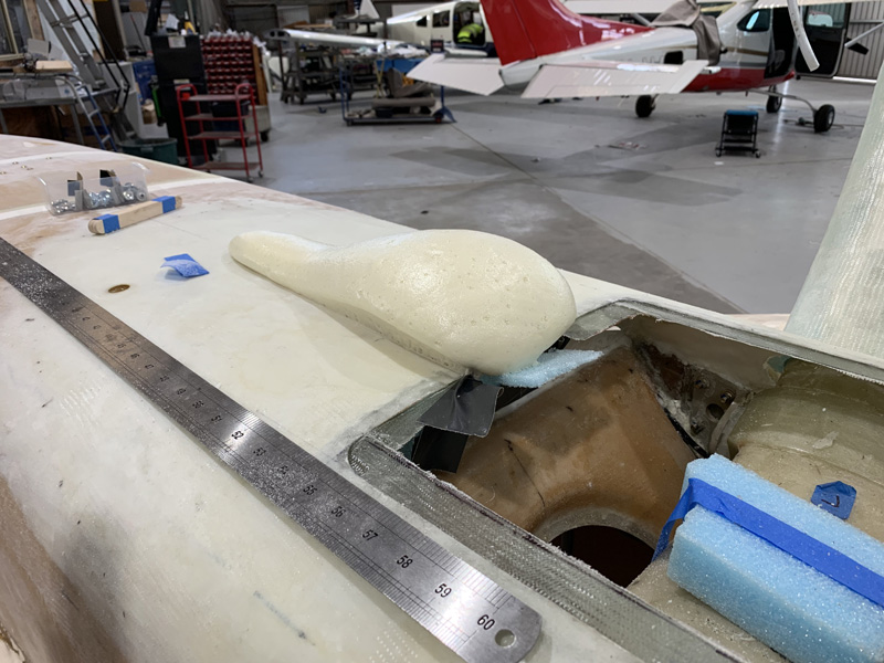
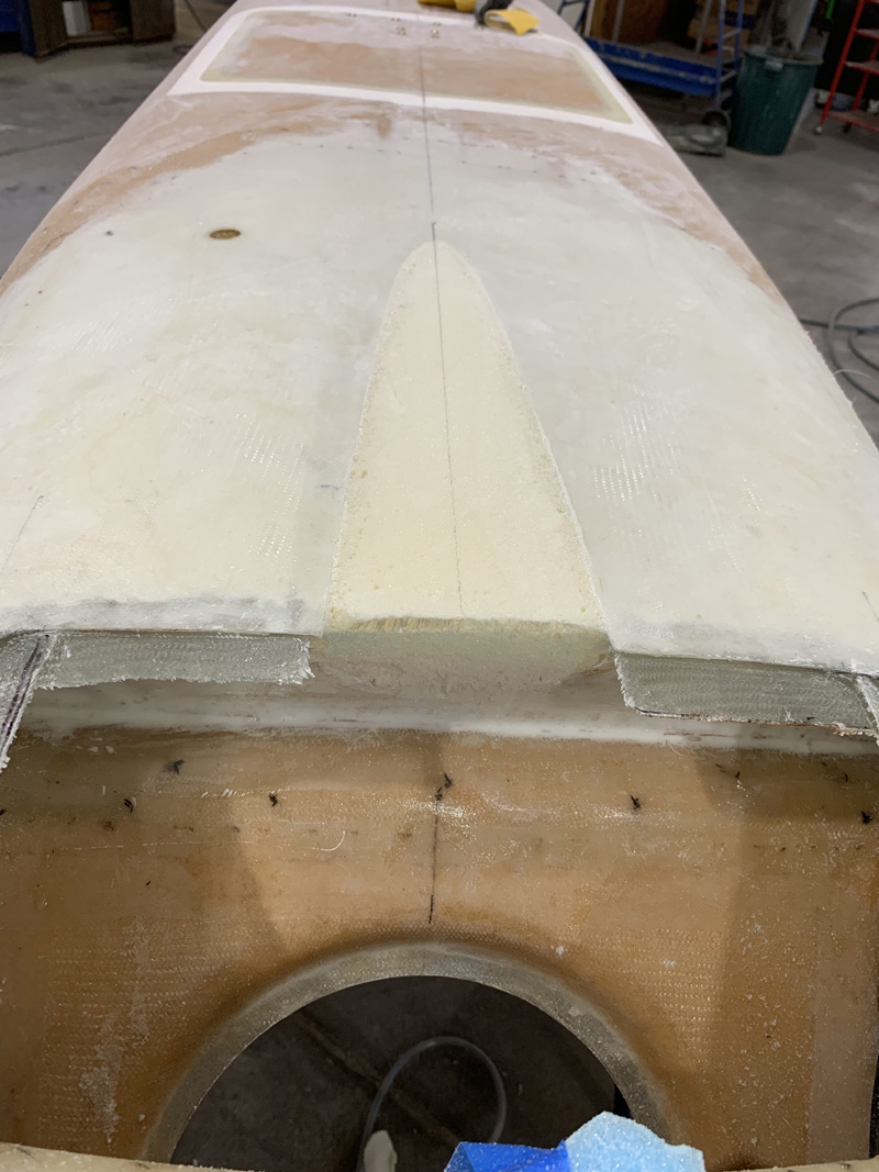
Meanwhile, my second effort in fitting the scoop is now far too deep. I pulled out my careful glass shape and also removed the micro. There is zero need to add more weight by being lazy and just filling in the scoop as is.
Once cleaned up I added pour foam which did its thing.
About 10 more minutes work and I again have a clean surface for my third go at fitting the scoop to the bottom. Wish me luck!

