| Date: 02-22-2024 | |
| Number of Hours: 30 | |
| Manual Reference: 23 |
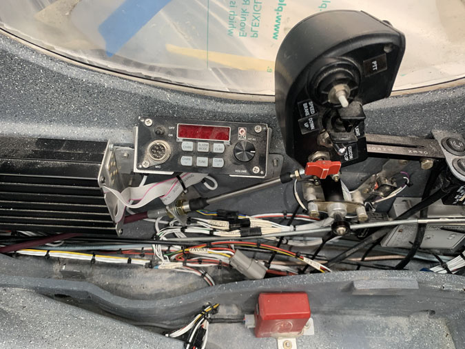
Time to connect the throttle in the cockpit to the throttle body at the engine. Another not so EZ (easy) little project.
I went through quite a process to get the length of the push pull cable I needed and then find someone who would make them. The process took some weeks but I thought I had the right one. The next issue was drilling a hole in the firewall and doing the cable run. Not so bad.
Meanwhile I found that because of the way the throttle was set up I needed a rod end rather than a simple clevis for attachment. I drove for nearly an hour to a place that has them for racing. I like the ones with the nylon insets so you never have to lube them. I paid the bucks, drove back to the hangar but for the life of me I couldn’t get it to fit. I was sure I had the specs correct!
Then I got a call. It was the rod end people to say they gave me a left hand thread by mistake and it wasn’t even a sealed one. The correct end as pictured above was a ten day wait and more money. I got to keep the old one if you ever need something with a left had thread. haha
Having positioned the cable roughly, I made an 2024 T3 aluminum bracket out of simple angle. I’m using click bonds for fasteners. My usual process is to make the fitting with holes then use that to position the little threaded bases with epoxy thickened with flox after I make notches in the bases to help key them in.
After they are fixed as above, I add two plies of BID glass to secure them. This is a super strong arrangement. A bit of grey paint follows so I can pretend I’m a tidy person.
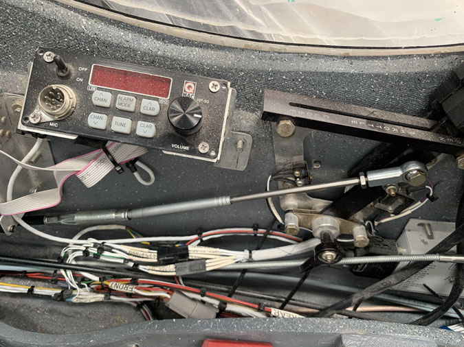
All done and we have a working cable at one end with about a 60mm throw.
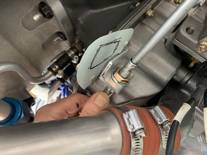
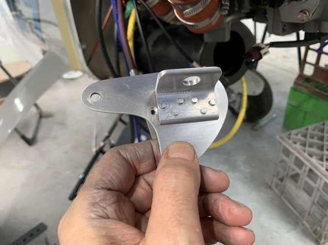
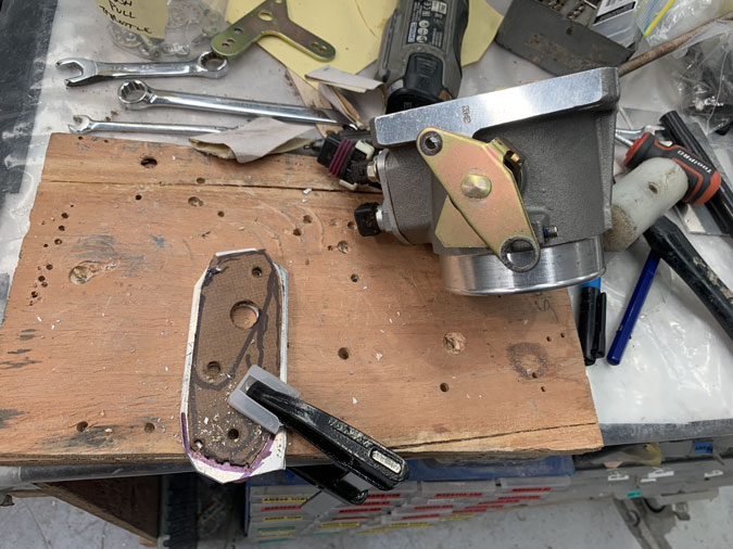
The next step is a bracket at the engine with the cable end pointing to where it needs to go. The attempt above is about the third try. This is roughly where it goes, or so I thought at the time.
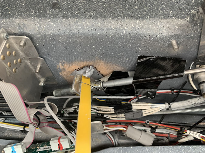
Here I’ve drilled it out and things are solid so I can see where we are up to.
I just don’t think this will work. I can’t get enough bend in the very expensive so called flexible cable to get the clevis fitting anywhere near the throttle-body lever. I’m not happy with the angles.
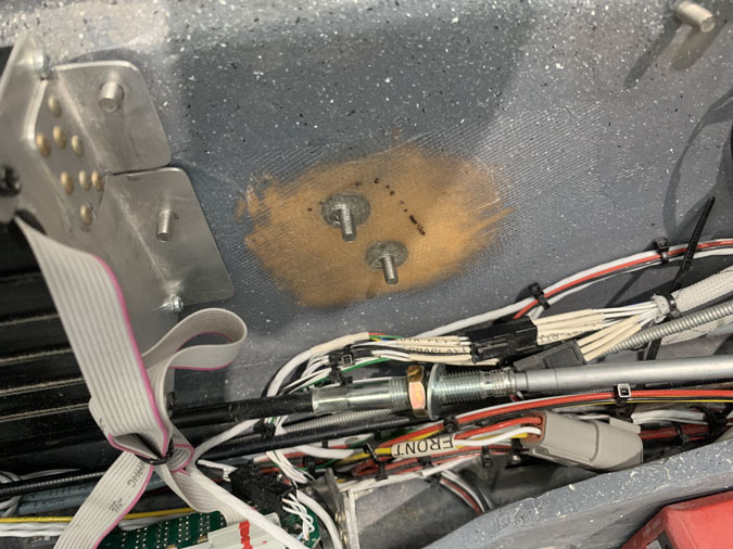
Notice anything here? The attachment bracket is located on different screws now and the cable is a different colour. Yes during this process I ordered, and had made after several delays, another cable. So I got to pay twice for one item. This one is MUCH more flexible. I put it in, didn’t like the feel and went back to the first one. After a while I couldn’t get that working right. So again went for the brown one.
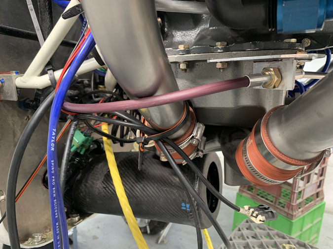
The newer brown cable in place at the cockpit end.. I spent some days putting this in and out. While the new cable is much better at tight bends, I realised that I might have issues with clearances in the engine bay when the left side radiator finally gets installed. I may have to put even more bend in the cable run. It is going to be tight.
I eventually made the bracket pretty and got rid of the screws in favour of some rivets.
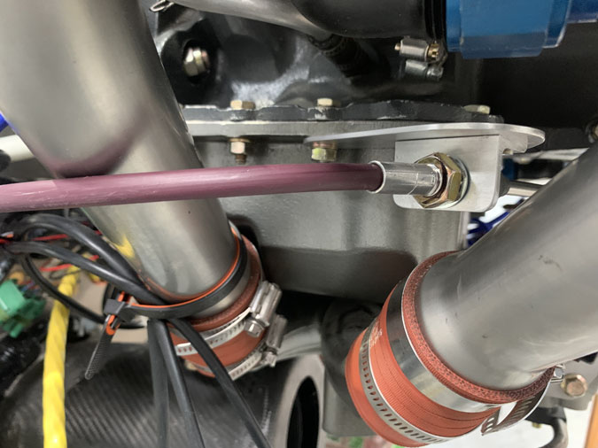
That bit is in place with a relatively tight curve on the cable and it seems to work well. No jamming or loss of smoothness. I MIGHT have to bend the cable in a little to clear the radiator when it comes but I feel this is manageable.
The final piece of the puzzle is to dial in the geometry so the throttle position fully open and fully closed in the cockpit exactly matches the same thing in the throttle body.
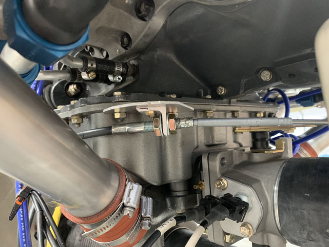
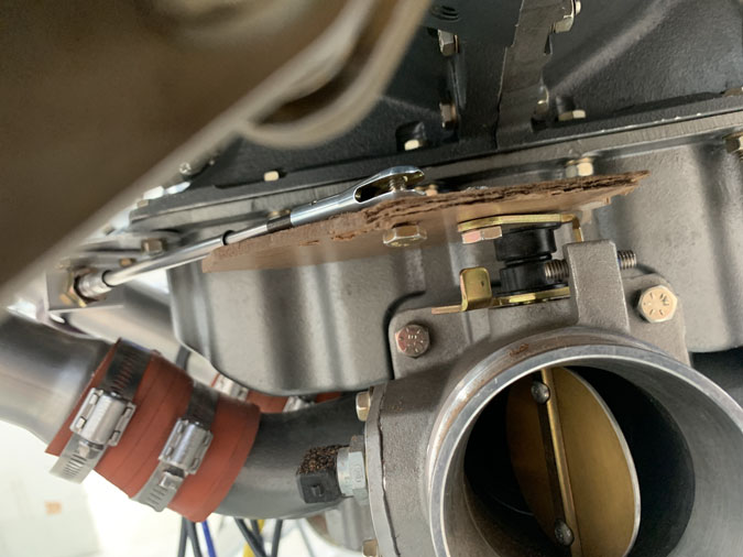
Here I thought I had it right still using my Masonite templates. I was wrong. I didn’t know it and went on to make some aluminium versions as you see me doing above. They were still wrong. In the end, I went home and slept on it.
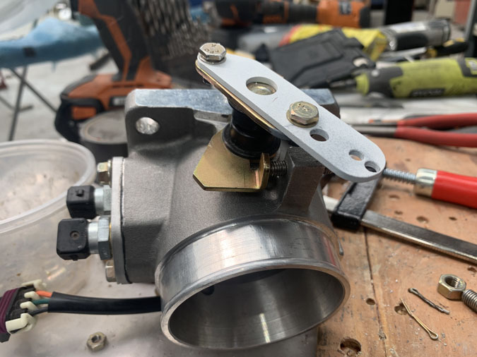
This is many hours later the next day and many iterations of a top plate. In the end I found I could alter the existing plate with a lot of grinding and it actually worked. I love it when you end up with an elegant solution after many tries at other configurations. You know when you have it right. …in the end. I have painted the fitting above as it is steel and hence a little corrosion prevention is required.
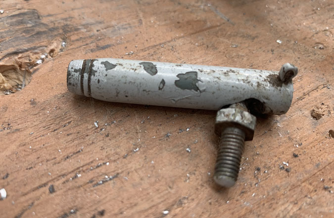
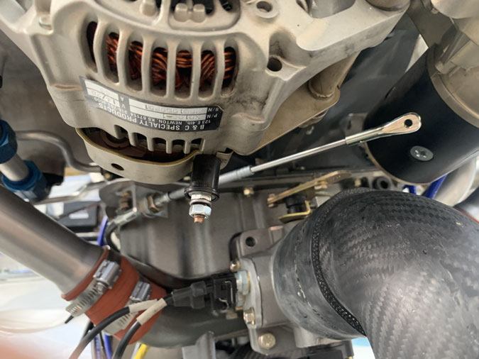
You might say ..”Is that something the cat dragged in?” You would be wrong. My next problem was to make my clevis fitting work with new modified throttle bracket. I got very luckly. Our resident sheet meet worker, craftsman and LAME had a look and said, “You need a rod end here, not a clevis”. He was right as usual. I started wondering how many weeks and a couple of hours driving were in my future to get a simple rod end.
Instead he said, “I’ve got what you need.” This was the perfect fitting from an old under carriage door in some GA airplane in his spares collection. I’d never even seen one of these although it is a standard part used in certified airplanes. It is also exactly the same length and thread as the clevis I had. Unscrew one, screw in the new part. Perfect fit.
I cleaned it up and added some primer and paint without getting too excited. (yes I will add a locking fitting on the bottom later)
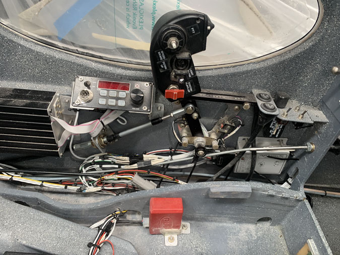
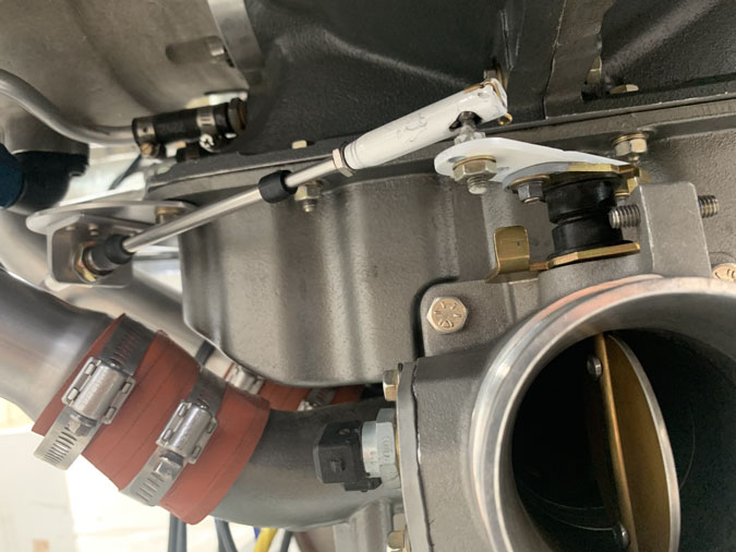
All dialed in I have a fantastic result. It is beautifully smooth and the geometry is correct. I do have adjustments if I need to fine tune this but I’m calling this one DONE.
Here’s the setup working.