| Date: 01-16-2025 | |
| Number of Hours: 16 | |
| Manual Reference: no ref |
Having solved the basic concept of how to open and close these flaps. It was a matter of refining the process.
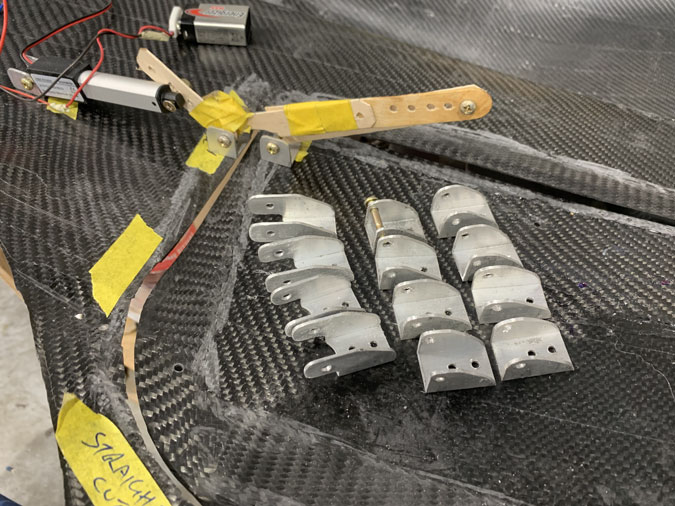
I made a bunch of fittings although something tells me these will not be the final ones. In a wide eyed way, I had hoped so.
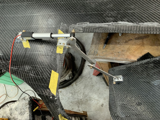
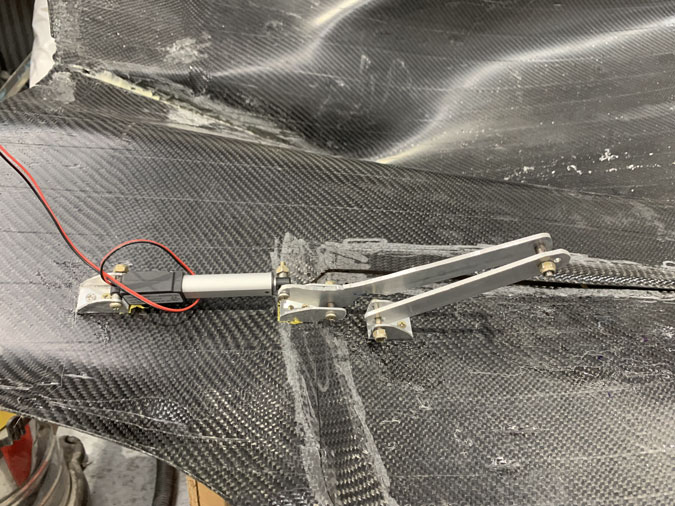
I got the arms working after a while with aluminium pieces and offsets with spacer inserts. A problem is that because of the compound curves the arms done pull straight up and they need to be in a bit of an arc. My little 9V battery didn’t have the power to pull them through.
Add a 12v aircraft battery and its a monster.
I refined it a bit but this is not a final result. After some thought I ordered some incorrect parts and have just ordered some more that will work. I’ve also lined up a machinist to make insets. I’ll show all this in a later post, assuming it works, or even if it doesn’t. In short I’ll use rod ends that are adjustable to replace the piece that bolts to the cowl door in the picture.
Meanwhile I have the proof of concept so lets move on.
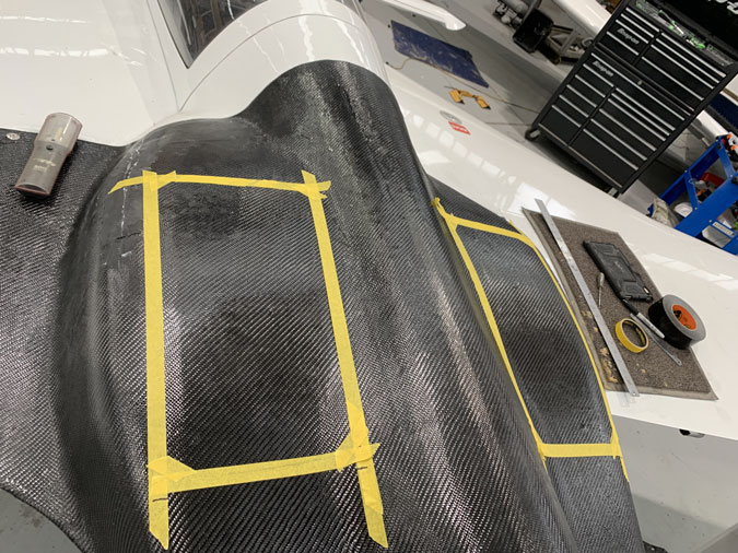
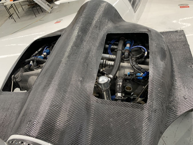
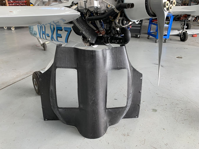
I marked out on my dummy top cowl the biggest doors I could make fit.
Given its a practice piece, I cut the holes out in about 5 minutes, freehand. Looking in from above, the pipes are exposed top and bottom. This is the source of the under cowl heat so if its visually open, the hot stuff will get out.
These are huge flap openings, go big or go home right? It will be some work to ensure the final cowl work is very strong with so much structure removed.
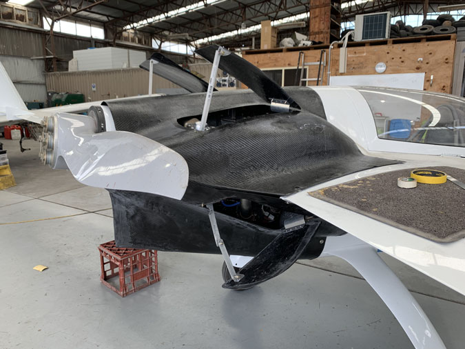
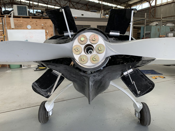
I added the same offset hinges to the other three flaps and secured them with screws. With the one bottom flap with a test mechanism that’s one flap open and taken care of.
Using the fittings I’d made earlier I secured the others with scrap aluminium. All I need is something that stays open and strong enough to go to the runup bay for testing and back again.
This has to be the money shot. An F16 look? I am ready to test.

