| Date: 12-24-2024 | |
| Number of Hours: 3 | |
| Manual Reference: no ref |
To solve this ground cooling issue I first need to make the fans more effective by building shrouds. That’s like a faring that sits an inch or so from the rear face of the radiator to gather air from the entire back area to be pulled through by the fans.
First I need a prototype for a proof of concept. I could just mock something up which would take quite some time. Then it it wasn’t quite right I’d have to start from scratch and build another, and another…
Wouldn’t it be great if someone could wave a magic wand over the radiator instead? After that they might made a gesture and point to a magic box. After more time a perfect shroud would just appear!
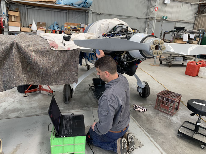
Here is a magic wand with a modern day wizard getting the 3D image.
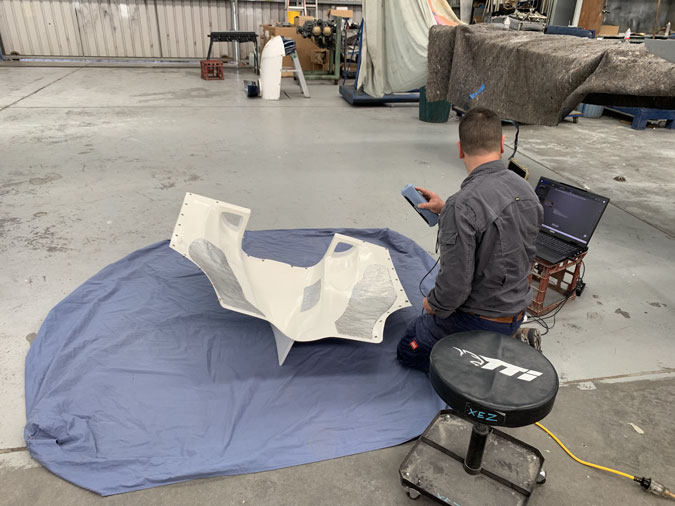
We need the cowl too so the images can be stitched together to give us the clearances. Wands are boring grey oblong boxes these days. It is still magic.
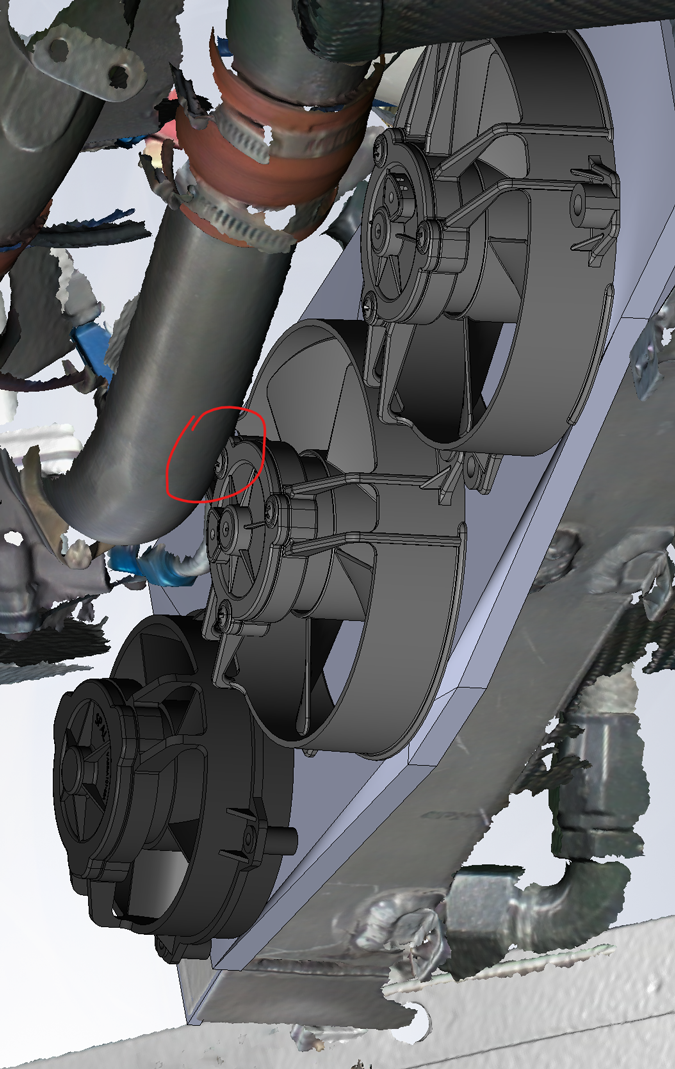
Here we have a problem revealed. A third fan is just too close to the induction pipe. In fact it will not fit. We could make that fan ‘remote’ but for now we will make a two fan solution and test with that.
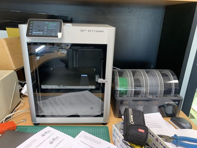
This is a magic box. It is used after the magic wand.
Magic is slow.
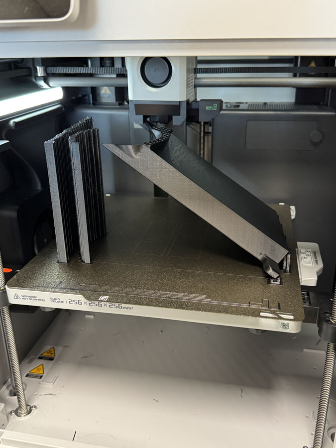
Magic is really slow. Layer by layer things pop into existence. This is just showing off.
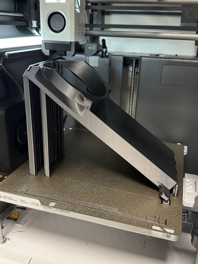
The first half of the shroud has now appeared and the fan fits perfectly on top. The second half will be ‘printed’ and then I’ll install it ready for testing. Of course the right hand side shroud also needs to be printed with this slow magic method.
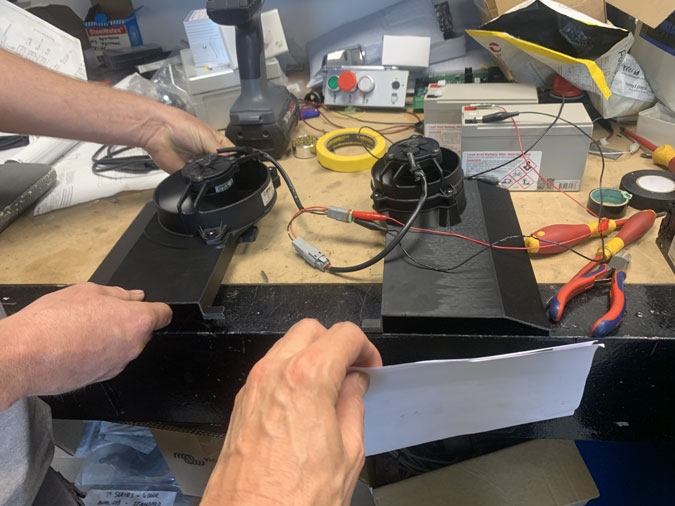
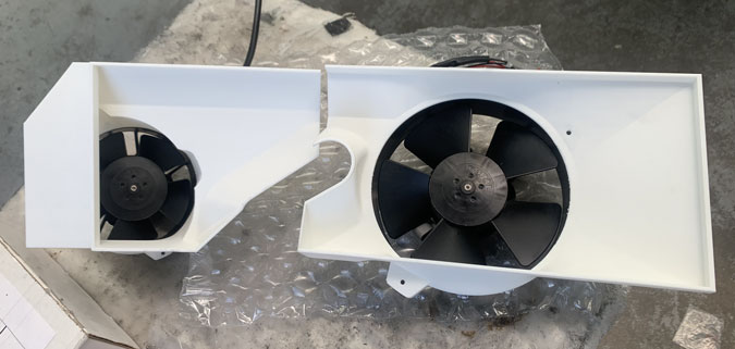
With the two half printed we did some more testing. Is a bigger fan but offset better than a smaller fan not offset and a bit further back. I expected the bigger fan to have more ‘suck’ where we placed a bit of paper at the respective openings. To my surprise the smaller fan sucked a LOT better.
OK a bigger fan centred would be better but I have space constraints. I have ordered another 4″ fan and we will be able, because of its size, space it a bit further back and in the centre in the next prototype. This creates a ducted fan effect which also helps.
I was in for another surprise. I had asked ‘Spal’ fan support how will I go with wear and tear when the fans are freewheeling at high speed. I didn’t get a good answer but he pointed out that as the incoming airflow gets stronger the fan motor works less. I thought it might fight against the flow and try to slow down. Wrong, it requires less and less current. Until it needs zero, then it acts as a generator and makes current for my electrical system!
My avionics guy knows all about this and showed me with meters that my fans freewheeling produce current so my alternator doesn’t have to work as hard. It should also help to accelerate the air after the fans and so reduce cooling drag. I’m liking these fans a bit more.
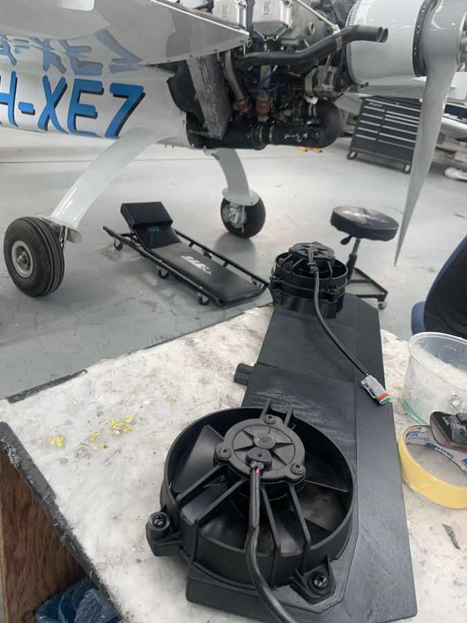
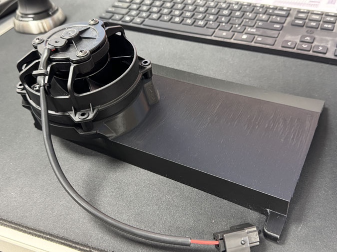
Here we have our prototype version 1 shroud. This is for proof of concept. I’ll need the second shroud printed before I can gaffer tape them on and do some testing.
The RHS shroud has been printed. We ran out of black ‘thread’ so white it is. Not so heat resistant it turned out later.
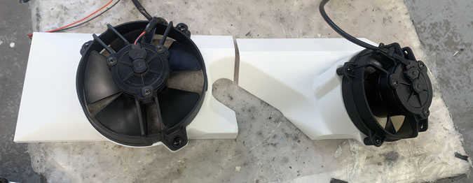
You can see a nice offset on the smaller fans. Going back a little further gives more ‘suck’. We are as usual very limited by the room available. The dip in the middle is for an exhaust pipe. Did I mention the lack of space?
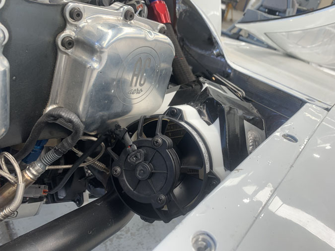
This is how it sits with gaffer tape. I did add some heat shielding to protect the plastic.
After taping the ducts in place a little preliminary testing was in order.
Here we have proof of concept. Before the shrouds there was very little ‘suck’ on the radiator face side. Barely enough to hold a sheet of paper. Now we have something worth testing. The next step is back to the runup bay and see what I have and collect the data. I am or rather was, hopeful of a good result.