| Date: 03-07-2025 | |
| Number of Hours: 110 | |
| Manual Reference: no ref |
Time for the upper flaps. I’ve been working 70 hours a week on this for some time and I didn’t expect things were going to get easier. Its just a matter of showing up and keep pushing. If you are thinking of cooling flaps for your Long-EZ, you have been warned.
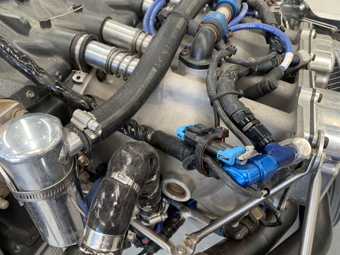
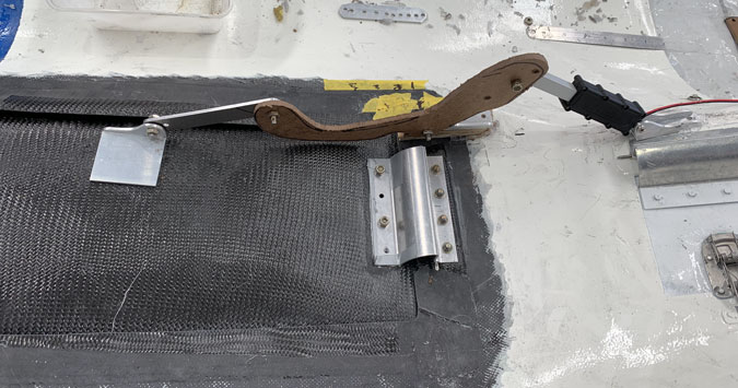
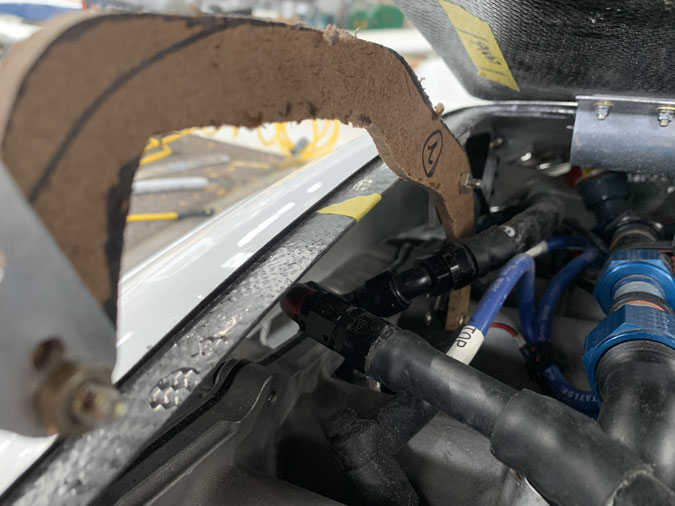
This is where the top right flap mechanism has to go. Weaved in-between that stuff on the left side. There just wasn’t room on the right side of the opening.
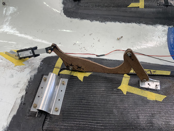
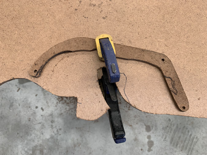
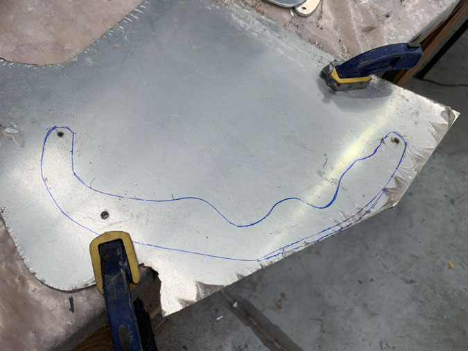
As usual I start with ‘Masonite’ shapes and scrap metal.
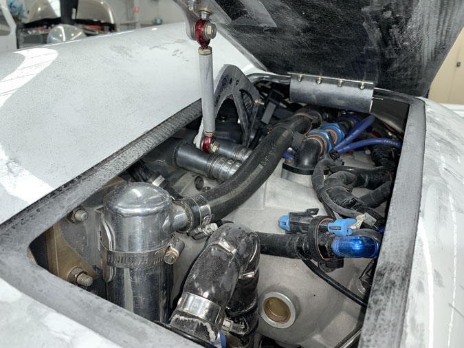
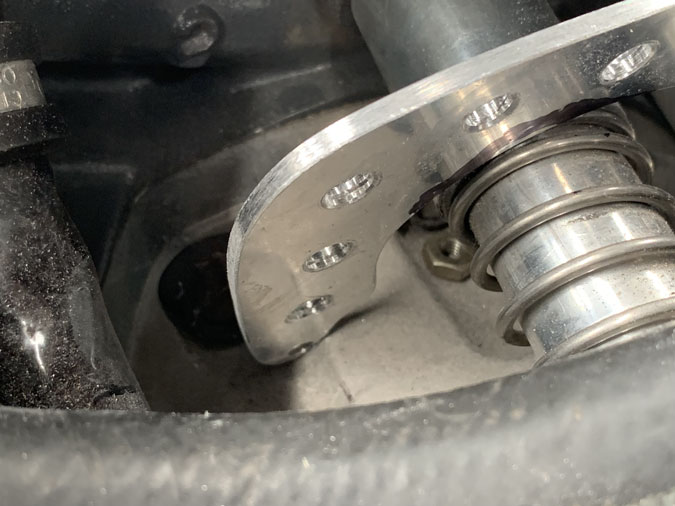
That smaller shinny black pipe is in the way of everything. I managed to move it .5″ with different fastener positions. I could just remove it, but then the engine wouldn’t run.
I kept playing with shapes and putting the cowl on and off the plane dozens of times, it feels like hundreds.
One of the challenges is getting the geometry right so the flap opens a certain amount. Then its lots of testing.
All seemed ok so I could go ahead with the hard point of .25″ marine ply.
The hardpoints get a ply of carbon to lock then in place although the fasteners really do that job.
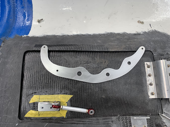
Given it all seemed to work I made the main pieces out of my 2024-T3 aluminium and tested again.
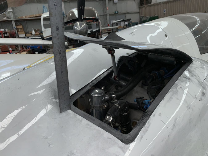
The opening I want is 190-200mm which is what is happening with the lower flaps. This is not critical and +/-5% will probably not be noticeable.
Everything seems to work.
Then for some reason, gremlins or evil fairies, it doesn’t quite fit anymore and I’m ‘just’ touching in a couple of places.
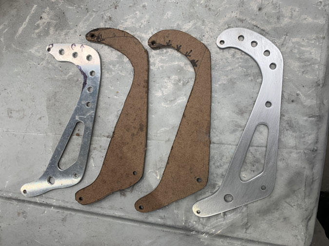
So despite making a ‘finished piece’ it was wrong and I got to make another one, after some more prototyping, which is the finished piece on the right.
I got it all working, happy days. So on to the left side upper flap. It has to be easier? Hahaha …of course not.
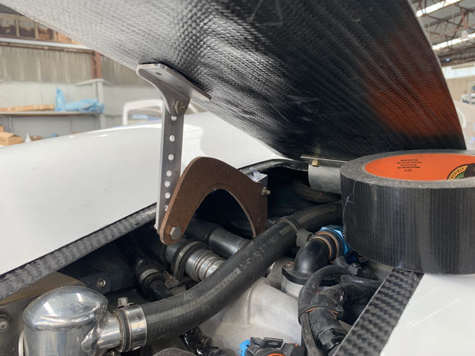
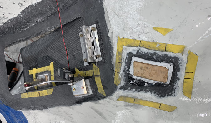
The obvious spot for this left side was to put the mechanism on the inside to match what I’d done on the right side upper flap. There seemed to be more room too. This was going to be easy.
I made my usual bunch of prototypes and endless off and on to ensure it was going to fit. I probably spent 20 plus hours and got the push arms to fit, but I just could not make the actuator fit in the end. It was just too near the engine mount. This was a fail.
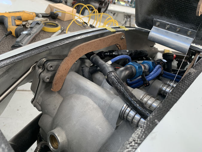
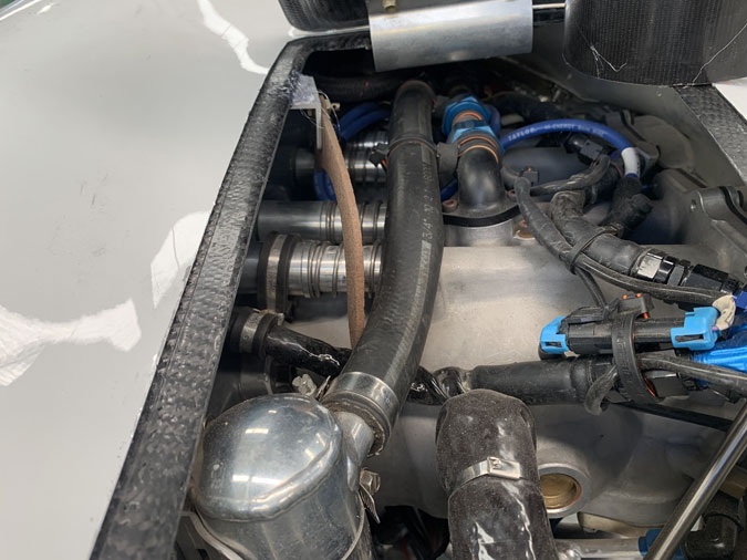
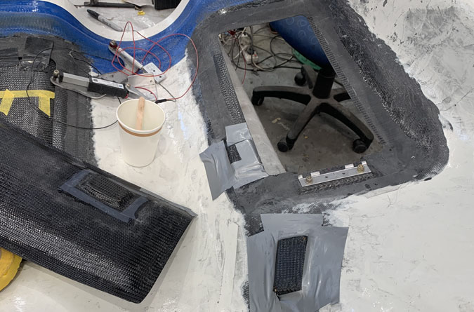
OK, I’m going to have to make it fit on the left side for this left flap. As you can see it just needs to fit around the engine and a few pipes here and there. On the plus side, there is heaps of room for the actuator.
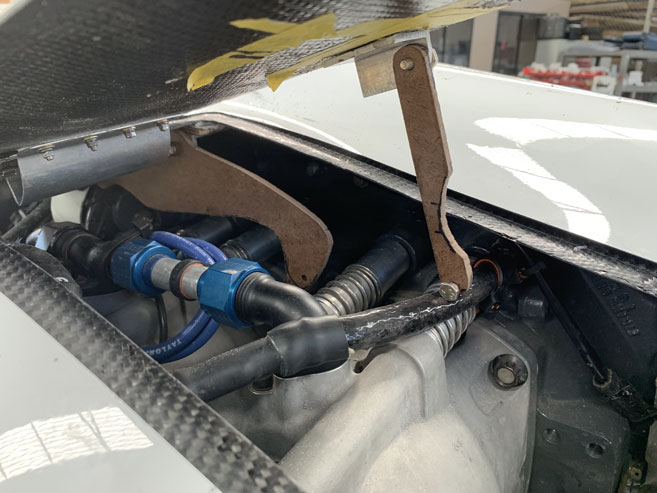
It was getting weird but one prototype gets made, then acts as a template for the next which has ‘modifications’.
More on and off testing.
Getting closer.

This is nearly it.
I did make a nice metal one before this as I had it nailed. Wrong, nearly nailed doesn’t count so here’s the next one after two more Masonite versions.
This is quite pretty, like some strange weapon from movie.
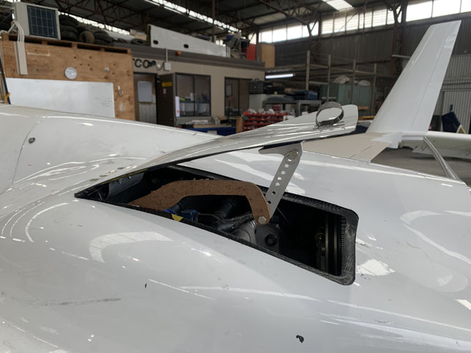
This works. There is a bit of a catch in the door opening and closing to do with the cowl curvature that I will address.
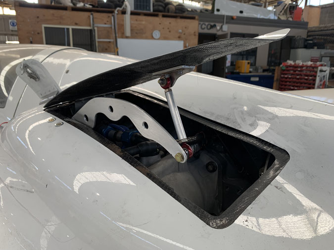
The four flaps now done with a working mechanism. Wooohoo!
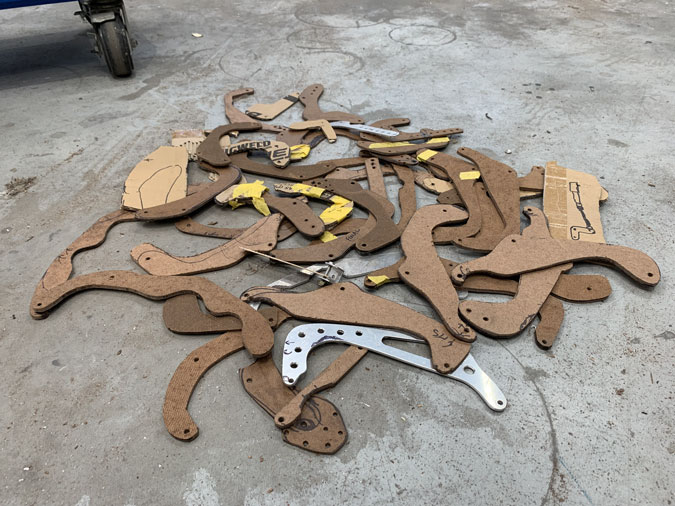
These are the prototype pieces that I made.
I don’t use CAD design and CnC cutters or plasma. I use MAD. Masonite Aided Design with a cordless jigsaw, drill, hand files and sandpaper.
I think this is more efficient as I can knock out a part pretty quickly. A final piece takes me around 2 hours and a few minutes for a prototype. It would be seconds with a plasma cutter…and days getting it set up just right and driving to someone’s place to do the job. Then waiting for it to be done, then finding out its nearly correct and needing another one made. My own gear would be huge time and expense. I need it now!
Next up is to design some sort of flap alignment system as these guys are likely to move around when closing in high winds and they might jam open or at least be glitchy. I’m not having that!
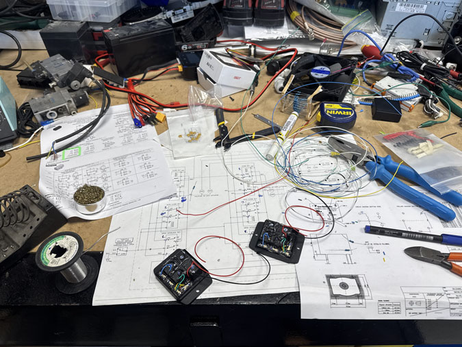
They also need the electronics, which is being worked on.