• Home
  • Flying
    • First Flight
  • Build by Chapter
    • Ch 3 Education
    • Ch 4 Fuselage Bulkheads
    • Ch 5 Fuselage Sides
    • Ch 6 Fuselage Assembly
    • Ch 7 Fuselage Exterior
    • Ch 8 Roll Over/Seat Belts
    • Ch 9 Main Gear/Landing Brake
    • Ch 10 Canard
    • Ch 11 Elevators
    • Ch 12 Canard Installation
    • Ch 13 Nose and Nose Gear
    • Ch 14 CenterSection Spar
    • Ch 15 Firewall and Accessories
    • Ch 16 Control System
    • Ch 17 Roll/Pitch Trim System
    • Ch 18 Canopy
    • Ch 19 Wings, Alierons
    • Ch 20 Winglets/Rudders
    • Ch 21 Strakes – Fuel/Baggage
    • Ch 22 Electrical System
    • Ch 23 Engine Installation
    • Ch 24 Covers/Consoles
    • Ch 25 Finishing
    • Ch 26 Upholstry
  • Build Mods
    • Liquid Cooling, Numbers, Weights and Flow
    • Cooling
      • Solving Ground Cooling 1
      • Solving Ground Cooling 2
      • Solving Ground Cooling 3
      • Solving Ground Cooling 4
      • Solving Ground Cooling 5
      • Solving Ground Cooling 6
      • Solving Ground Cooling7 – Test Data
      • Solving Ground Cooling 8 – Flap Building
      • Solving Ground Cooling 9 – Hinges
      • Solving Ground Cooling 10 – Lower Flaps
      • Solving Ground Cooling 11 – Upper Flaps
      • Solving Ground Cooling 12 – Completed
      • Cooling the Beast 1
      • Cooling the Beast 2 – Lower Cowl Expansion
      • Cooling the Beast 3 – KW Oil Cooler Diffuser
    • EVS (Enhanced Vision System)
    • Cowl Keeper
    • Rudder Gust Locks
    • Wing Fences
    • Post Cure
    • Hinge Upgrade
    • RAM Air & Hellhole Cover
    • Main Gear Beef Up
    • Pilot Side Windows
    • Baggage Pods
    • Winglet Intersection Fairings
    • Titanium Rollover
    • Nose Gear Doors
    • Wheel Pants/Gear Leg Fairing
    • Cabin heating System
    • Fuel System
    • Roll and Pitch Trim
    • Oxygen System
    • The Ferry Tank
    • Cruise Angle Indicator
    • Fire Extinguisher Install
  • Round the World
    • RTW Route East #12 rev1
    • Survival Equipment
    • Training Flights
  • Other Stuff
    • Blog
    • Around the World: RAAUS Sport Pilot Issue 110
    • Taxi Tests
    • Summary Feb ’24 from an SAAA Meeting
    • AOPA Pilot 27th Sept 2019
    • Build Tests
    • Flying Stories
      • A Long Easy Dream ’06
      • Townsville ’07
      • Cairns ’08
      • Albany ’08
      • East Coast ’08
      • Brisbane ’09
      • Cairns ’10
      • Perth ’10
    • Non Build Mods
      • F16 Scoop for JZE
      • Ram Air Box for JZE
      • Strange Tips
    • Milestones
    • Links
  • Contact

Blog

Home
Ch 16 Control System
Rudder Cable Routing from the Fuselage to the Hot Side

Rudder Cable Routing from the Fuselage to the Hot Side

6 years ago
Dave Berenholtz
Ch 16 Control System
Date:  04-05-2019
Number of Hours:  16
Manual Reference:  16-7

This is really a modification. Instead of the plans bellcranks and pulleys for the rudder cables I am going from the fuselage straight through to ‘present’ to the wing. This has been long planned without knowing exactly how.

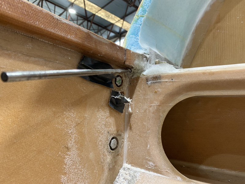
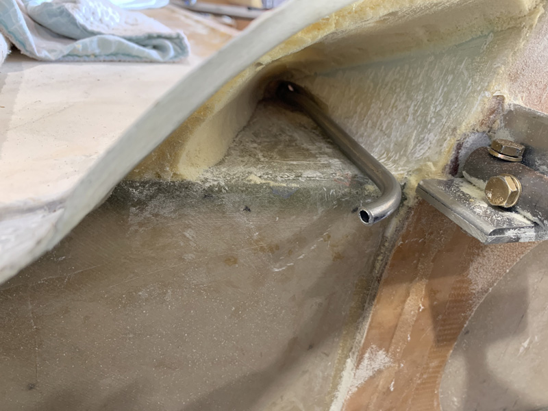
After many many days thinking and looking I finally got my long drills out and made a hole each side. I’m partly in the longeron, then skimming the top of the spar without penetrating it and out the other side.

Having the Melvill cowls meant I had to make a faring and this turned out to be a great place to get the rudder cable conduit through.

I dug out a bit of the pour foam to make a place to get the cable through. Now I realised its best to get the tubing sitting right on top of the spar. I may need to add some cooling air here so I like knowing I have this option with no ‘cable in a tube’ in the way.

I used some soft 3000 series tube to make a ‘model’. Then this is in 2024 T3 left over from the canopy controls. The tube is the perfect size to contain the nylaflow inside it.

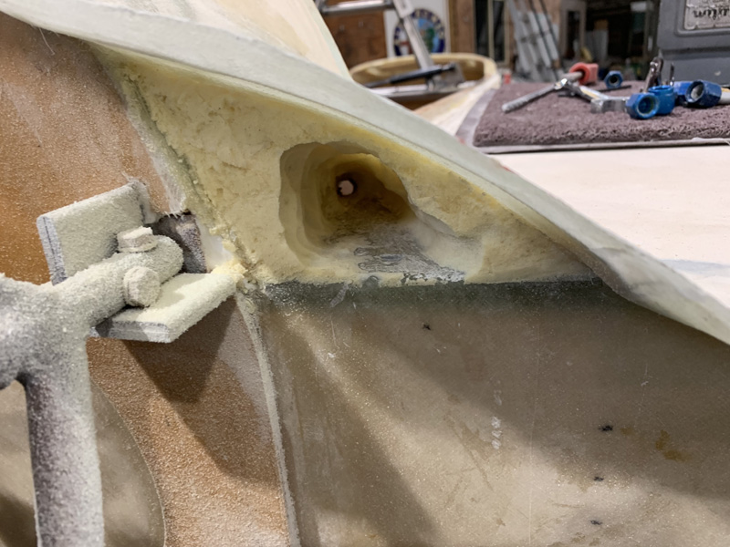
This is roughly where the pipe will go and then pointing directly at the wing cable exit. You might notice I’ve really cleaned out a lot of the pour foam. I initially left it as I felt it was adding strength in case I rested on the bulge during maintenance. It is very strong with very little foam, so who needs the extra weight?

I tested earlier with a bit of tube and the cable slides perfectly around the corner with very little resistance.

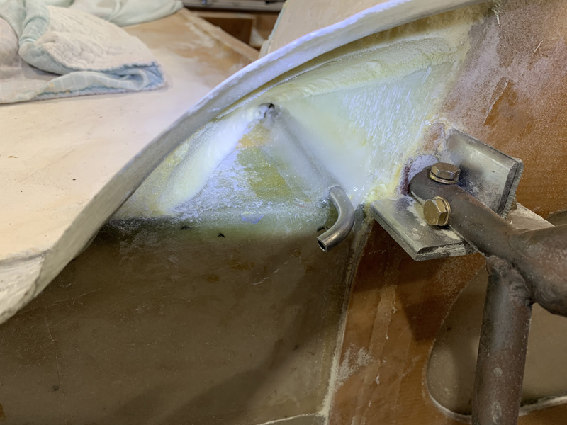
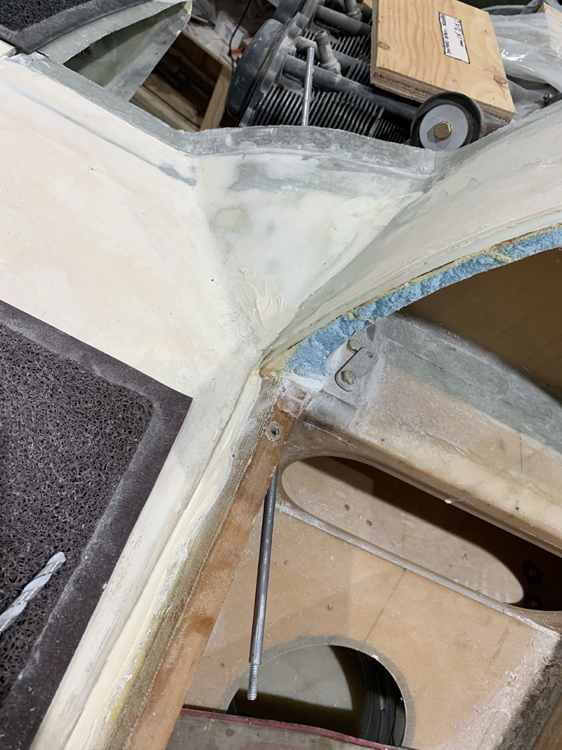
After a LOT of work and checking I finally floxed the ‘outer’ tubes in place.

I added a piece of BID (2 plies) so there will be plenty of strength for when I introduce the nylaflowΒ  into this area.

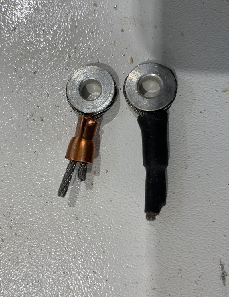
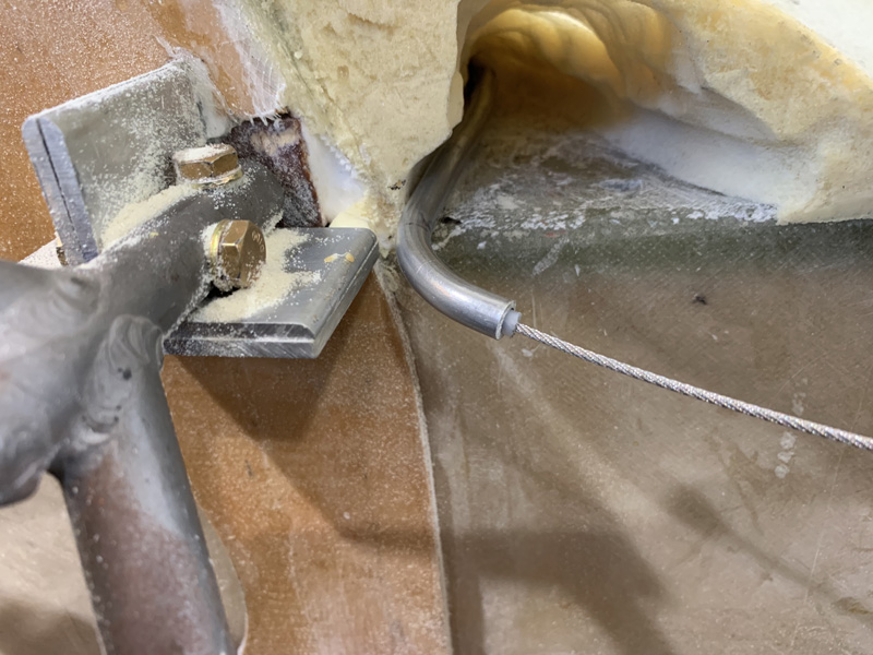
A few words on those AN111-4 fittings. I found that if you swage it up close and tight it looks like it would be a lot of strain on the cable turning so sharply.

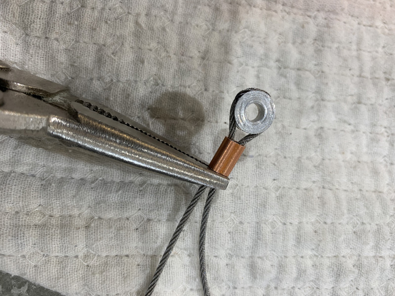
I found that about this much slack works out pretty well once you get the nicopress tool on it.

This is still very secure but I believe not as much strain on the cable. Just my own idea, I’m not a cable guy. It just seems common sense.

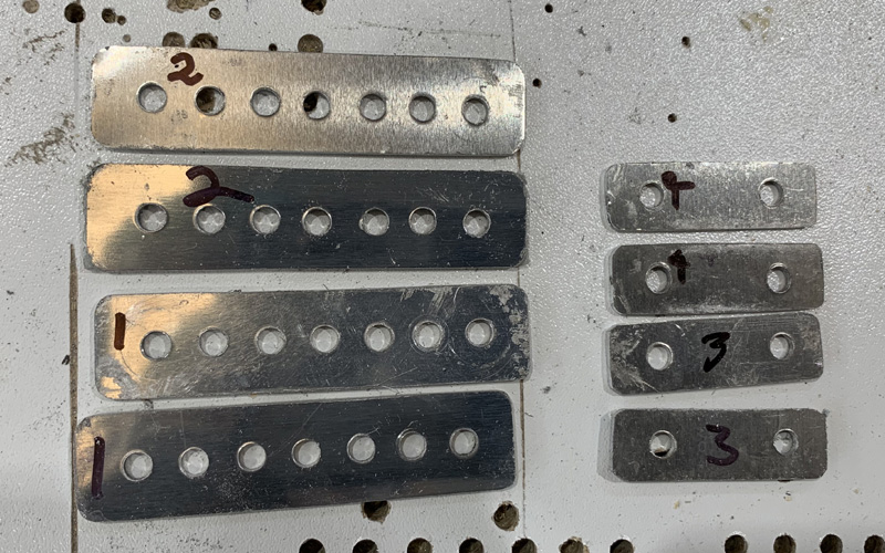
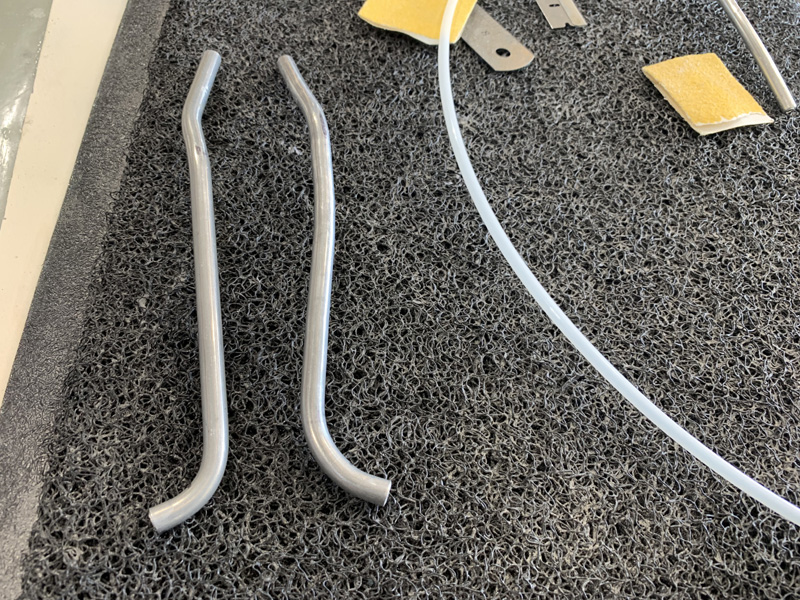
While I was endlessly working on the cables I made up a set of quick release joiners and a set of rudder position cable length adjusters. 2024 T-3 and .063″

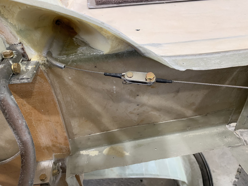
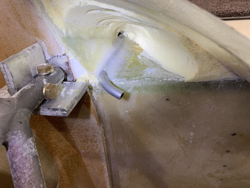
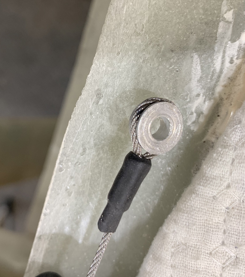
Although without the nylaflow in the tube yet you can see that the fitting is well clear of the upper cowl line. I might add I’ll be changing the fuselage side fitting to the AN111. I think I need 8″ of cable slack to get the rudders off without cutting the cable each time. There is very little margin here.

I have the idea that this would be a great place to put the cable length adjusters INSTEAD of the smaller quick release. This makes more room up front where the special double direction spring has to go. If I go with this I will have to redo all the cables and make the adjusters shorter. Shorter adjusters is kinda not the point! So I’m still thinking on this one.

Having done all this work with the plans 1/16″ SS (stainless steel), I am now told by real ‘experts’ that I should have used galvanized 1/16″ cable instead.Β  I’m nearly convinced, so I just might trash all the work and go again.Β  It will be very quick now I’ve sorted out the problems.

Another issue is that I’m unhappy with my rudder pedal position. I have plans measurements but they are not as comfortable as my flying Long-EZ, so I’ll be looking at sorting this out. Maximum comfort to reduce fatigue is very important on this build.


Previous Post
Rudder Cable, Winglet end
Next Post
Firewall Aileron Bearing

Leave a Reply Cancel reply

Your email address will not be published. Required fields are marked *

Fill out this field
Fill out this field
Please enter a valid email address.

CategoryLogsHours
All157617079
Uncategorized135
Ch 3 Education220
Ch 4 Fuselage Bulkheads25231
Ch 5 Fuselage Sides32283
Ch 6 Fuselage Assembly30270
Ch 7 Fuselage Exterior14140
Ch 8 Roll Over/Seat Belts990
Ch 9 Main Gear/Landing Brake71642
Ch 10 Canard28287
Ch 11 Elevators36298
Ch 12 Canard Installation12102
Ch 13 Nose and Nose Gear1291097
Ch 14 CenterSection Spar57525
Ch 15 Firewall and Accessories448
Ch 16 Control System27237
Ch 17 Roll/Pitch Trim System654
Ch 18 Canopy70502
Ch 19 Wings, Alierons1271090
Ch 20 Winglets/Rudders71528
Ch 21 Strakes - Fuel/Baggage65437
Ch 22 Electrical System591031
Ch 23 Engine Installation961152
Ch 24 Covers/Fairings/Consoles25202
Ch 25 Finishing561084
Ch 26 Upholstry340
Fuel System46310
Rollover1050
Cabin heating System60331
The Ferry Tank335
Blog2694182
Build Mods2252513
Nose Gear Doors856
Wheel Pants/Gear Leg Fairing40473
Oxygen System762
Roll and Pitch Trim964
Winglet Intersection Fairings445
Baggage Pods11104
Pilot Side Windows437
RAM Air & Hellhole Cover15177
Main Gear Beef Up322
Post Cure124
Fire Extinguisher16
Wing Fences13
EVS (Enhanced Visual System)130
Hinge Upgrade115
Cowl Keeper110
Rudder Gust Locks19
Cooling20607
Taxi Tests42
Flying10

Complete the Test Flight Program

2025/6/30 10:26:01

Round Australia in Four Flights

2026/4/1 10:26:01

Round the World Departure

2026/8/22 10:26:01

Rough River Flyin, Sept 23, 2026

2026/9/23 10:26:01

Β© Copyright 2025 Dave Berenholtz