• Home
  • Flying
    • First Flight
  • Build by Chapter
    • Ch 3 Education
    • Ch 4 Fuselage Bulkheads
    • Ch 5 Fuselage Sides
    • Ch 6 Fuselage Assembly
    • Ch 7 Fuselage Exterior
    • Ch 8 Roll Over/Seat Belts
    • Ch 9 Main Gear/Landing Brake
    • Ch 10 Canard
    • Ch 11 Elevators
    • Ch 12 Canard Installation
    • Ch 13 Nose and Nose Gear
    • Ch 14 CenterSection Spar
    • Ch 15 Firewall and Accessories
    • Ch 16 Control System
    • Ch 17 Roll/Pitch Trim System
    • Ch 18 Canopy
    • Ch 19 Wings, Alierons
    • Ch 20 Winglets/Rudders
    • Ch 21 Strakes – Fuel/Baggage
    • Ch 22 Electrical System
    • Ch 23 Engine Installation
    • Ch 24 Covers/Consoles
    • Ch 25 Finishing
    • Ch 26 Upholstry
  • Build Mods
    • Liquid Cooling, Numbers, Weights and Flow
    • Cooling
      • Solving Ground Cooling 1
      • Solving Ground Cooling 2
      • Solving Ground Cooling 3
      • Solving Ground Cooling 4
      • Solving Ground Cooling 5
      • Solving Ground Cooling 6
      • Solving Ground Cooling7 – Test Data
      • Solving Ground Cooling 8 – Flap Building
      • Solving Ground Cooling 9 – Hinges
      • Solving Ground Cooling 10 – Lower Flaps
      • Solving Ground Cooling 11 – Upper Flaps
      • Solving Ground Cooling 12 – Completed
      • Cooling the Beast 1
      • Cooling the Beast 2 – Lower Cowl Expansion
      • Cooling the Beast 3 – KW Oil Cooler Diffuser
    • EVS (Enhanced Vision System)
    • Cowl Keeper
    • Rudder Gust Locks
    • Wing Fences
    • Post Cure
    • Hinge Upgrade
    • RAM Air & Hellhole Cover
    • Main Gear Beef Up
    • Pilot Side Windows
    • Baggage Pods
    • Winglet Intersection Fairings
    • Titanium Rollover
    • Nose Gear Doors
    • Wheel Pants/Gear Leg Fairing
    • Cabin heating System
    • Fuel System
    • Roll and Pitch Trim
    • Oxygen System
    • The Ferry Tank
    • Cruise Angle Indicator
    • Fire Extinguisher Install
  • Round the World
    • RTW Route East #12 rev1
    • Survival Equipment
    • Training Flights
  • Other Stuff
    • Blog
    • Around the World: RAAUS Sport Pilot Issue 110
    • Taxi Tests
    • Summary Feb ’24 from an SAAA Meeting
    • AOPA Pilot 27th Sept 2019
    • Build Tests
    • Flying Stories
      • A Long Easy Dream ’06
      • Townsville ’07
      • Cairns ’08
      • Albany ’08
      • East Coast ’08
      • Brisbane ’09
      • Cairns ’10
      • Perth ’10
    • Non Build Mods
      • F16 Scoop for JZE
      • Ram Air Box for JZE
      • Strange Tips
    • Milestones
    • Links
  • Contact

Blog

Home
Blog
RHS Radiator Duct 1

RHS Radiator Duct 1

1 year ago
Dave Berenholtz
Blog, Ch 23 Engine Installation
Date:  02-11-2024
Number of Hours:  16
Manual Reference:  23

The design of the first radiator duct has been on my mind for a few years now. There had to come a time when it was the next job, ready or not.

On a FB friend’s suggestion, I got in touch with ‘Jac’ in the Netherlands. He was a protege of the late and great airfoil designer, John Roncz, who did the flying surfaces for the Voyager as well as the Long-EZ ‘Roncz’ canard that I built for my plane.

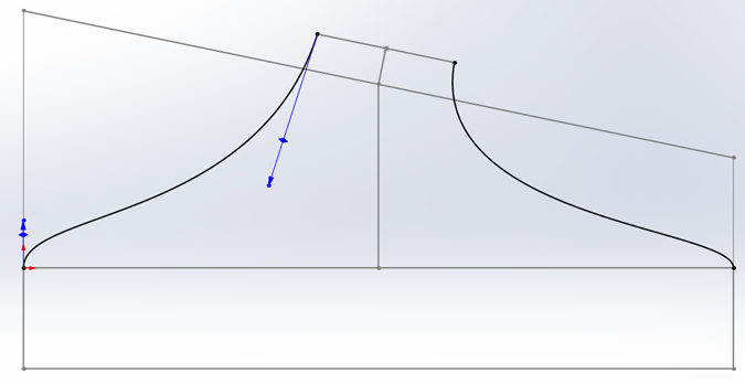
Jac very generously has engaged in a few discussions about my ‘fluid dynamics’ problems. He is an expert in the field doing very large commercial projects. After we talked about KW trumpet ducts he sent the above drawing which is a KW with modified ends. My issue here is that I can’t really make the neck of the duct anywhere near long enough to get the incoming air to spread evenly over the long surface of the radiators.

This RHS is the worst of the two radiator placements. I’m looking at a small puller fan as you might have in a motor car down one end which may help with ground cooling. Hopefully it won’t be needed in flight. These fans can pull 5-6 amps each and I’m running out of alternator capacity.

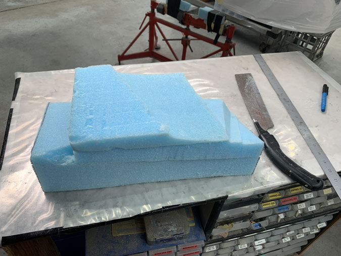
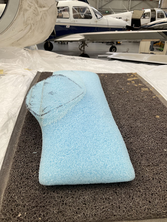
With no idea of what I really needed, I just stuck some foam together that was way too big. Its a start, right?

This stuff is easy to carve, My nice big duct was getting smaller and smaller.

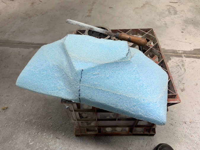
In the end to make it fit I had a pretty slim unit, The issue was also how do I get the cowls on and off AND get an airtight seal on the duct? I’ve been wondering on this for a year or so too.

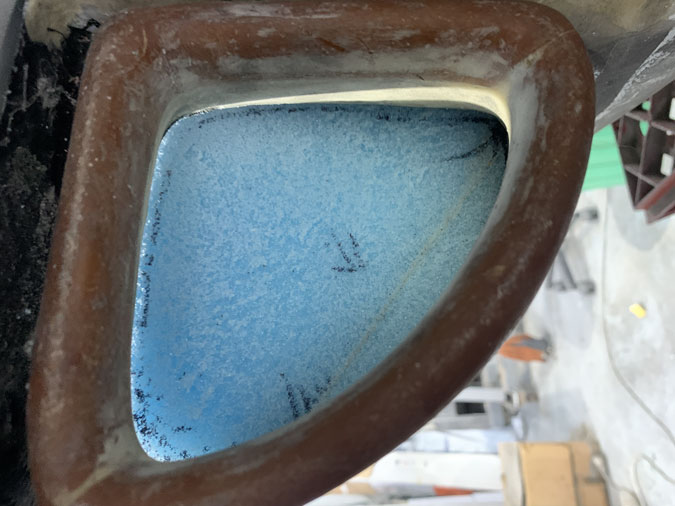
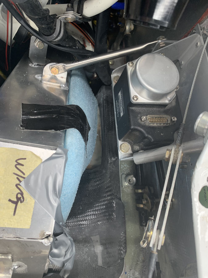
This is what the air sees. It turns out that the duct is in the way of my fuel return pipe. That’s another job to sort out later.

Not exactly my gentle trumpet shape with a nice long neck.

In fact my duct is almost the opposite of this ideal KW duct. Lets face it, the RHS to the radiator is just something that seals to the radiator from the incoming armpit scoop. Nothing fancy going on here.

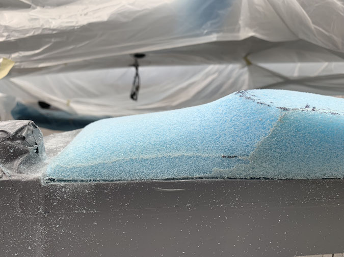
I do have a tiny bit of curve.

Well a really small amount of curve that isn’t going to get the air spread as I would like it. An electric fan at one end is a certainty in my future.

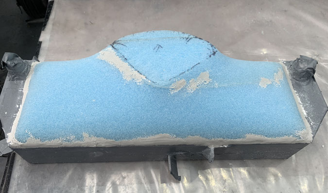
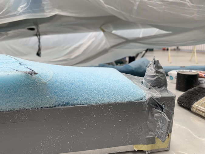
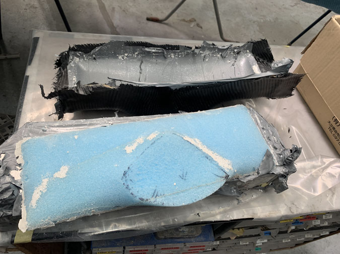
Here I have the radiator covered in duct tape and I’ve just used spray adhesive to hold the foam in place. Soft modelling clay was then stuffed in the edges and over a few gaps to give me a consistent surface.

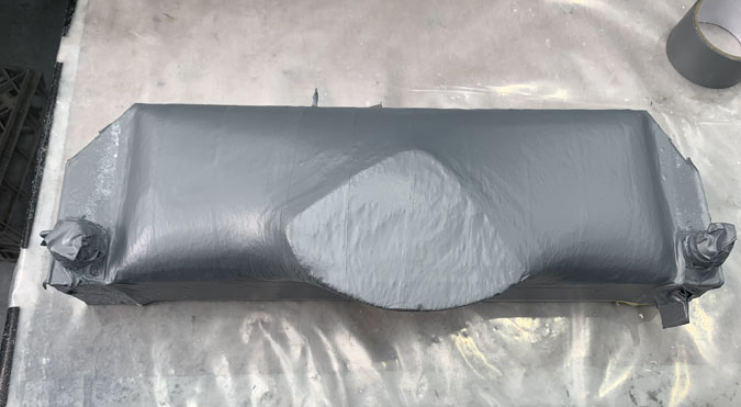
Next comes more duct tape which is my ‘mold release’.

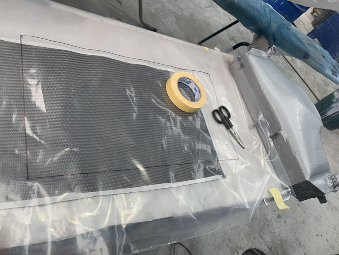
I’ve used three ply of carbon BID, so what you see above three times. I wet them out and then apply each ply separately one on top of the other..

With the three plies applied, I left it overnight sitting on top of my high tech hot box. This has an old school light glob in it. I’ve used that same box for heating my epoxy the last 12 years. I have replaced the globe a few times.

After the usual and expected trouble I got the cured part off the mold. When I say trouble, I just mean it takes patience and some time.

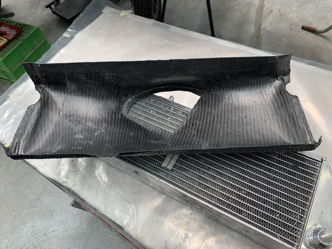
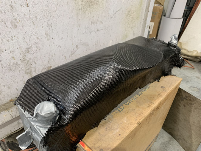
After a clean up, the part came out pretty well. I could do a light sand on the inside but it really doesn’t need it.

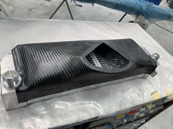
This is the initial trim. The radiator end tanks are just tacked on for now. Once the final welds are done I will probably have to cut the ends off the duct and put new ones on for a nice tight fit. That’s an afternoons work. No problem.

The next ‘radiator duct task’ is to work out how I am going to seal the thing. I have an inch or so gap to the armpit duct. It might be just foam around the edges or a bit more of a structure. I’ve gotten this far, so it’s time to set it all up again…and just stare at the thing for a while until I think of something.


Previous Post
Mounting the Right Side Radiator2
Next Post
Replace Fuel Return Line

Leave a Reply Cancel reply

Your email address will not be published. Required fields are marked *

Fill out this field
Fill out this field
Please enter a valid email address.

CategoryLogsHours
All157617079
Uncategorized135
Ch 3 Education220
Ch 4 Fuselage Bulkheads25231
Ch 5 Fuselage Sides32283
Ch 6 Fuselage Assembly30270
Ch 7 Fuselage Exterior14140
Ch 8 Roll Over/Seat Belts990
Ch 9 Main Gear/Landing Brake71642
Ch 10 Canard28287
Ch 11 Elevators36298
Ch 12 Canard Installation12102
Ch 13 Nose and Nose Gear1291097
Ch 14 CenterSection Spar57525
Ch 15 Firewall and Accessories448
Ch 16 Control System27237
Ch 17 Roll/Pitch Trim System654
Ch 18 Canopy70502
Ch 19 Wings, Alierons1271090
Ch 20 Winglets/Rudders71528
Ch 21 Strakes - Fuel/Baggage65437
Ch 22 Electrical System591031
Ch 23 Engine Installation961152
Ch 24 Covers/Fairings/Consoles25202
Ch 25 Finishing561084
Ch 26 Upholstry340
Fuel System46310
Rollover1050
Cabin heating System60331
The Ferry Tank335
Blog2694182
Build Mods2252513
Nose Gear Doors856
Wheel Pants/Gear Leg Fairing40473
Oxygen System762
Roll and Pitch Trim964
Winglet Intersection Fairings445
Baggage Pods11104
Pilot Side Windows437
RAM Air & Hellhole Cover15177
Main Gear Beef Up322
Post Cure124
Fire Extinguisher16
Wing Fences13
EVS (Enhanced Visual System)130
Hinge Upgrade115
Cowl Keeper110
Rudder Gust Locks19
Cooling20607
Taxi Tests42
Flying10

Complete the Test Flight Program

2025/6/30 10:26:01

Round Australia in Four Flights

2026/4/1 10:26:01

Round the World Departure

2026/8/22 10:26:01

Rough River Flyin, Sept 23, 2026

2026/9/23 10:26:01

© Copyright 2025 Dave Berenholtz