| Date: 09-21-2024 | |
| Number of Hours: 20 | |
| Manual Reference: 23 |
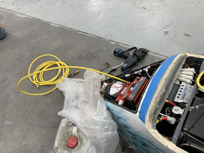
July 21 2024 This was our first attempt at starting the plane. An exciting moment. Simon, my super capable avionics/electronics guy was on hand. He is also a pilot and aircraft owner which adds to the pool of knowledge. Darren my long time friend who had helped with some of the big layups on the plane was operating a phone camera to record our success. It turns out physics when applied to aeroplane engines doesn’t care about optimism.
As you can see, an epic fail. For a start, the cranking is really slow. The energy from the batteries is losing current by the time it gets to the starter. We tries both batteries separately and then together (in parallel) which is available on the panel. No luck. I have 4AWG size cables and the voltage loss is too much for this very large tight engine. We thought at the time this was the only problem.
We got the battery cart out and applied power directly to the starter motor bypassing the plane’s batteries and start button. It was really the old school “Contact” with the jumper cables to get the start. You can see even with all that power to the engine starter it was struggling. I had a bit of work to keep it running too and what’s with the backfires? It seemed to run OK and idled very well down low but it wasn’t sounding smooth. We put all this down to the preserving oil getting cleaned out on the first run.
We were wrong.
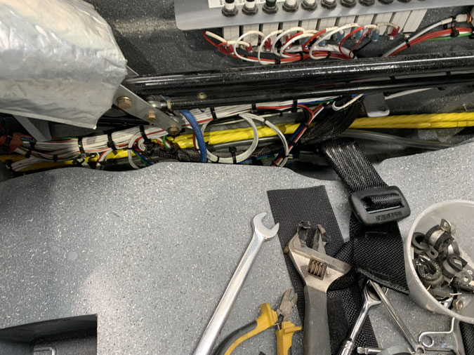
We thought the issue must be the cable size. I ordered 2AWG CCA cable to replace the 4AWG throughout the plane. This was no small task and it took a couple of weeks to get cable from the USA. This is a lighter weight copper clad aluminium that has less voltage drop that pure copper and less weight. It is slightly fatter however which added to the installation challenges.
I did mention this job in a previous post but here we are again for context.
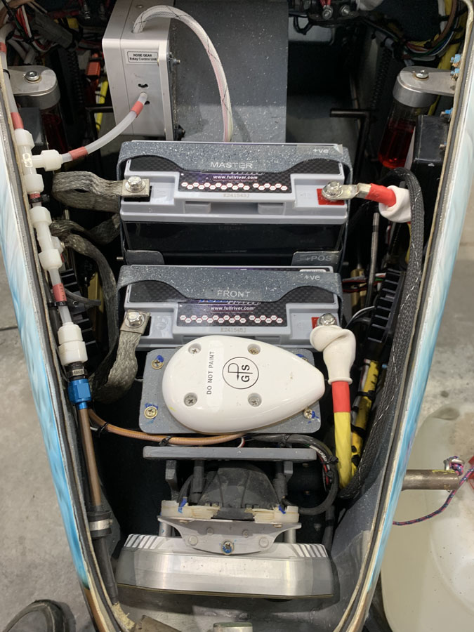
My batteries were not in perfect condition and one was charging poorly. I bought two new HC20 which have more CCA (cranking amps) and supposedly the same foot print as the PC680’s. No they don’t. An hour or two carefully rounding the corners of the batteries had them fitting in my holders.
21 September 2024 With new cables and new batteries, without the spark plug leads, we cranked it over in the hangar. It did crank faster and we thought OK, job done. This is not going to break prop speed records but we felt it should start the engine. Job done. …….but it wasn’t.
We had also addressed another huge issue. Clearly from the first start we could tell the timing was wrong. How could this be? The engine had been run for 25.2hours before delivery. Well a few of us had noticed that there was zero wear of the flywheel AND the starter motor. The engine builders must have used their own for whatever reason and bolted these on before delivery.
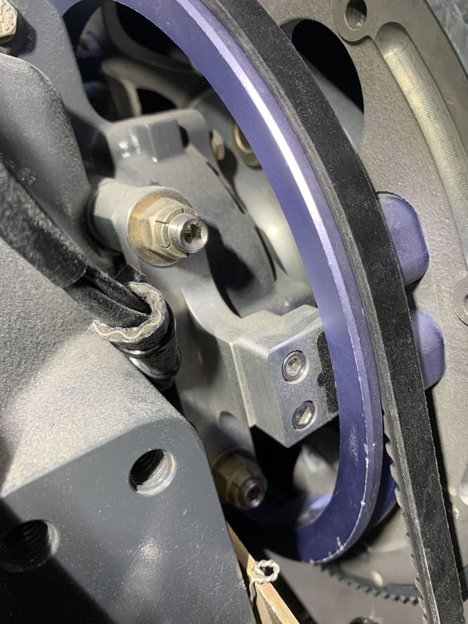
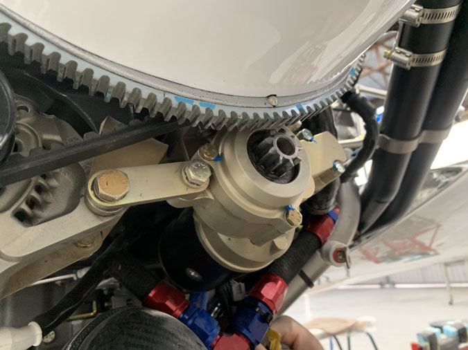
The ignition is triggered from three magnets imbedded in the purple pulley ring you see above, This is in turn bolted to the flywheel. Quite a few emails went back and forth to Robert Paisley at EFII. Robert is fantastic at support and one of the many reasons I went with his EFII System 32 ignition and fuel injection.
Eventually we got the numbers of degrees past TDC which we could measure. At a certain point when the ignition is triggered it shows on the engine monitor. Well to our, lets say, ‘surprise’, this was nowhere near correct. The magnets were in the wrong position! No wonder we had a problem starting. The flywheel came off and we got the ring orientated correctly, there are a few ways you can bolt it on and it was 180 degrees wrong. This took a bit of head scratching as the email instructions seemed a bit cryptic, it is a hard thing to explain in words.
So we had found the problem and were confident that the next start attempt would go well. <sigh> Read on if you want to.
We tried to start but still had a problem. The cranking wasn’t all that fast, even on both batteries, and it just would not run. There was also a loud clicking noise. During our attempts it looks like the starter on one of the backfires kicked out a tooth on the flywheel!
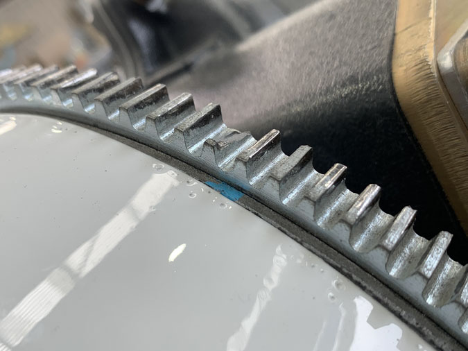
So we still have a timing issue and I need a new ring gear, but there was something worse yet to come.
Yes the engine groans, perhaps ironically. I’d been aware of this really tight spot where this sound is since I got what sometimes feels like a $100,000 brick. Given my plans, I really thought I needed to ask the engine designer about it. A few people has said its just a tight engine and this is not uncommon. That is until they heard the noise. Well I was told I needed to find out what it is and that I should do a bulk strip of the engine. In Australia you are looking at $30,000 to $40,000 and maybe six months. GA has declined here with engine shops being in small numbers now and long waiting lists. I was not happy.
I was lucky to have ‘The Engine Whisperer’ working in the hangar. He spent some time on it as a person who has many years with these things. He could tell by feel that it wasn’t rings but either thrust washers or main bearings. Apparently you can tell by the amount of play relative to the sound when you move the prop. It was still a bulk strip.
He then measured the endplay which came in at .0015″. Lycoming says .002″ to .006″. Given the tight tolerances of this design and a pretty rough measuring dial gauge setup we can call this good. Zero play would have been a big problem.
After some reflection and the next day there were another series of prop wiggling and listening for a new diagnosis. The sound wasn’t loudly present that day although the tightness was still there. An ear to the rocker covers found the problem. It is the rockers moving in the new bronze bushings that have not bedded in that is causing the squeaking and the tightness at that spot. Apparently this is common on newly overhauled engines on their twins which have a similar size powerplant to mine.
As this was a familiar problem, with the source of the sound isolated, I’m calling this one solved and I can sleep better at night again. For once, the engine will self heal. Meanwhile we still have the no start issue.
You might need a few plays. We get down to 4.49 volts and 499.7amps!!! OK, momentarily but this engine is NOT happy. The tight spot is probably where the peaks are. What is going on?
After lots of discussion about what to do next we thought we would try a bit of a scattergun approach. That is when you just start replacing things after no clear idea of what the problem is.
The Chief Engineer in the hangar had gabbed a starter motor from the store and offered it as something to try. A very generous thing to do.
Here’s the old starter, which has had less than 60 seconds of use in total. Clearly never used in the previous engine running before delivery. Its a B&C and I don’t think its faulty. It is string enough to break a flywheel tooth after all!
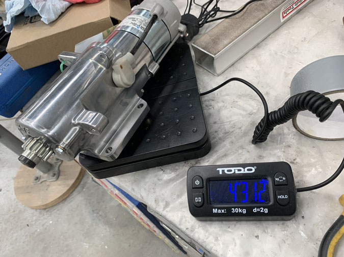
Here’s the new SkyTec starter. Just under a pound lighter and very surprisingly despite the longer footprint, there is room to fit it.
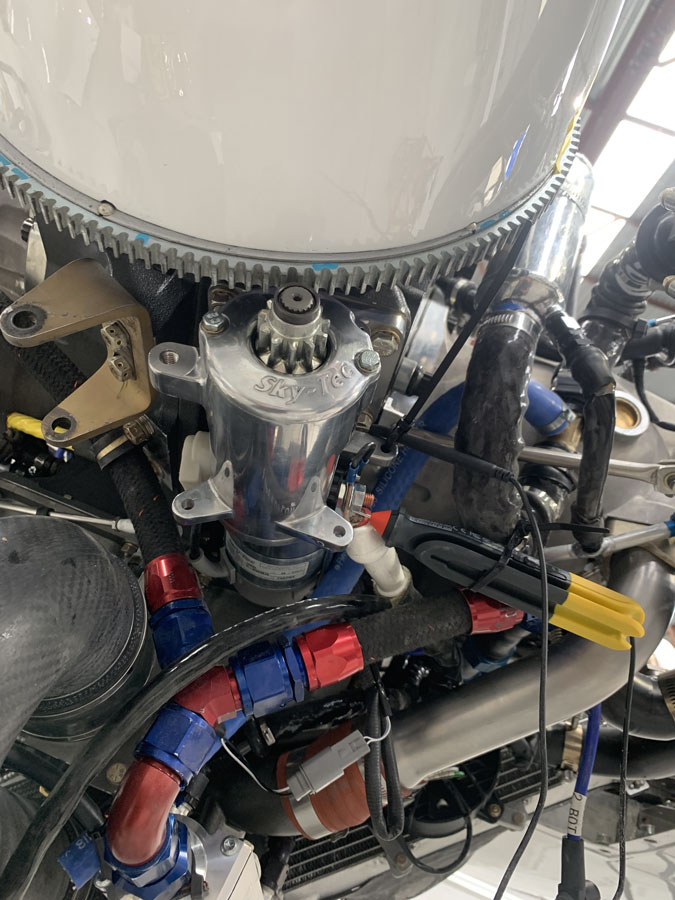
Simon did the bulk of the work to get this thing installed. We had to play with the main cables a bit and find a new link to the alternator but we got it done.
Here we go with the SkyTec. I don’t have video of the meters but peak current was nearer 200amps and voltage drop not lower than 6volts. You can see the prop isn’t going to break the sound barrier at the tips with its rotation speed BUT it is hugely improved on the old starter. I think this one should work.
The SkyTec has a permanent magnet rather than an energised field, I wonder if that’s the difference? So I have rotation speed with my own airplane batteries and the cranking might be sorted out. I think the current drop was causing the B&C to retract just momentarily and throw out the starter gear and that’s what broke the tooth.
Lets go back to this picture. Given we still have the timing issue I sent this shot off the EFII. We think we have the timing ring in the right spot so what’s up?
I’m told that the magnets don’t line up with the pickup dead centre. OK I tried to move the pickup but it has no sliding adjustment. The magnets were also placed a little off-centre in the purple ring which adds to the problem. It further turns out that the magnet to pickup gap should be 1/16″, my gap was 1/8″! I can fix that but not the other problem.
I need a new flywheel gear given the broken tooth. I have a Skydynamics lightweight flywheel with a custom fitted pulley ring. Given a few factors, the magnets are slightly off centre, this flywheel gap is a problem, my weight and balance issues with extra weight at the back turned out to be unfounded, I can take a regular weight flywheel.
A new Superior flywheel with installed magnets which are standard from EFII is in the mail. Will this be the answer to solve the timing issue? You will have to all wait, as I am, for my next blog post to find out.