| Date: 09-08-2018 | |
| Number of Hours: 10 | |
| Manual Reference: no ref |
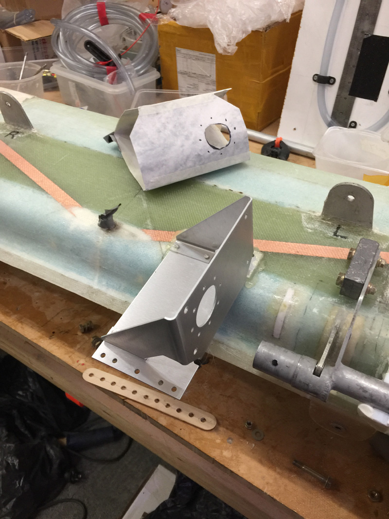
As VH-XEZ will be a well equipped IFR aircraft, I’ll be having an auto pilot. I’m using mainly Garmin instruments and this means a GSA 28 (Autopilot Servo) for pitch and another will be installed later for roll. I’ve been in touch with the very helpful guys at Garmin, some of whom have Long-EZ. They tell me the place to install these servos is on the canard.
I read the install manual a few times and got familiar with things. I’ve already bought the servos and a bracket kit. It looked like it goes somewhere in the above area. I made a cardboard cutout after a while as I just couldn’t see how to get the the canard on and off once I install the servo! It was snagging on all the nice air sealing work I’d done. The offset torque tube I’m using also made things harder because the counterweight also seems to snag.
As I’m saying more and more, “No modification goes un-punished”.
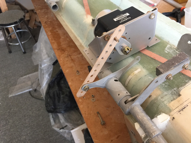
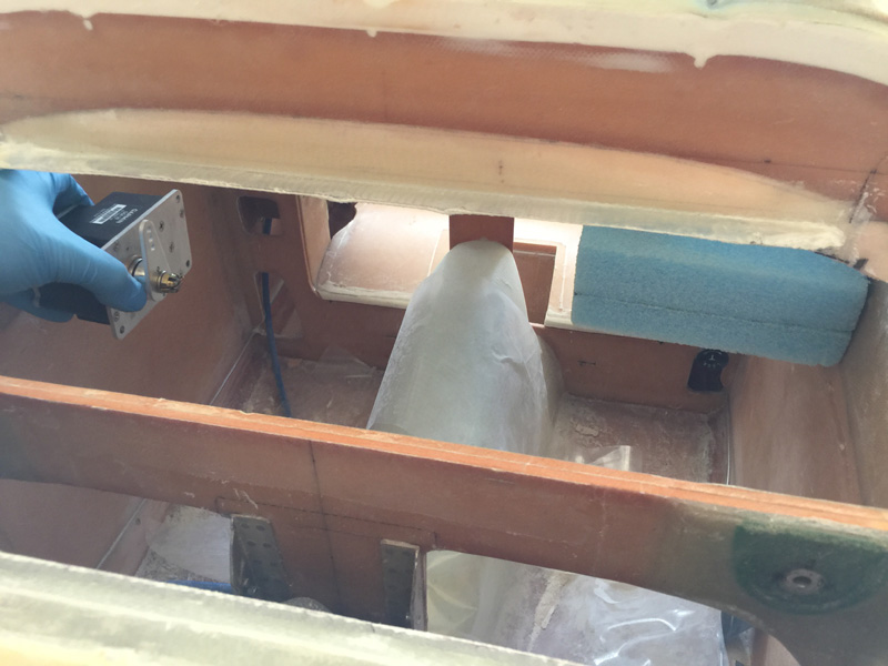
I had purchase the trim bracket with this servo in mind. I guess this was a rare planning win. You can see above a beginning of how it might fit and operate. I’m just using a drilled mixing stick to get a feel for placement and the ‘throw’ of the servo and elevator together.
I have concerns about how far from the canard edge this thing needs to go so I can still get the canard off. With hot gluing things in place I tried several positions.
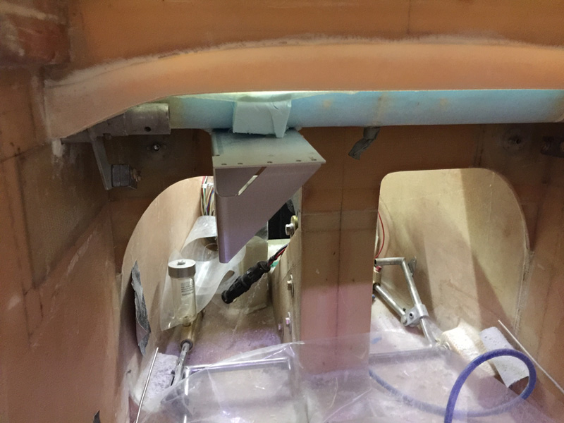
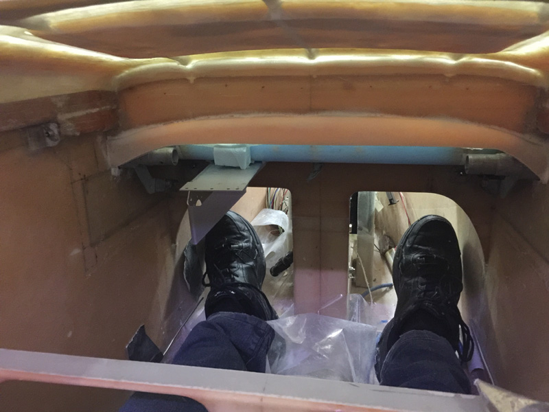
This spot seemed pretty good. My feet work out OK.
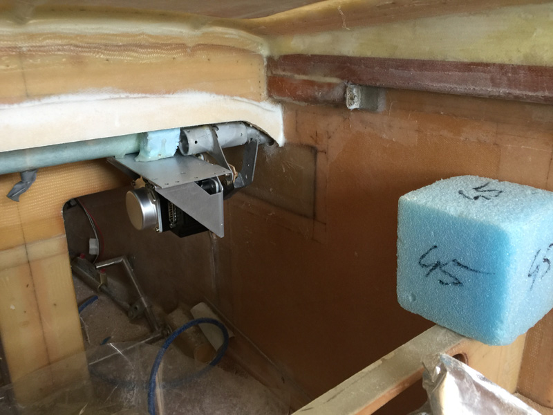
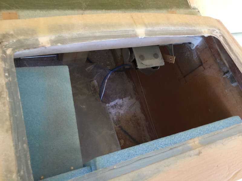
Here’s the reverse angle. That blue block is the radio stuff going full length forward to F28 (I think it is). Fellow LE builder and ace planner, Wade Parton, commented that I might run into trouble with my Garmin main stack of toys on that side being too deep. He was right, thanks Wade! Maybe I would have spotted it in time or maybe I’d be in a world of hurt in a few months doing the avionics install. Now we will never know.
Here’s a mock up on the opposite side All I have in from here is the G5 which is not very deep. There is still plenty of room for the pitch arm from the stick that goes on that right side. This is another mock up with more hot glue.
Each time I have to lift the canard off and manipulate it in my small room. Its been a couple of dozen so far. I may need a physio, things are starting to hurt.
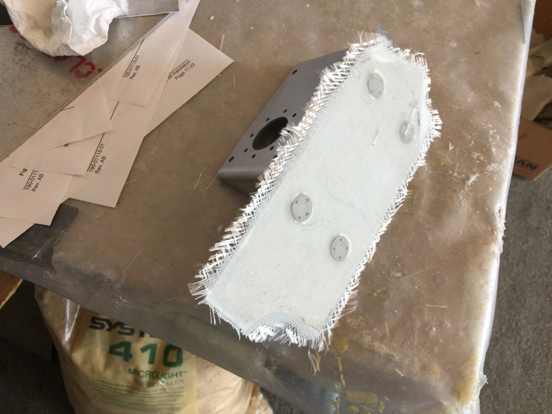
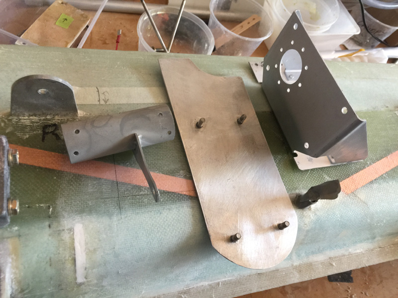
Now I’m happy with placement I hunted everywhere for a bit of aluminium for the base. I’ve added click bonds and then glassed over the back with a ply of BID.
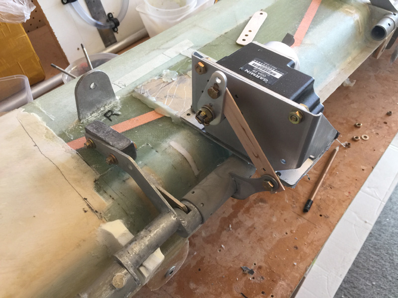
More mock up tests. You can see I’ve modified the pitch trim arm too. The canard again went on and off several times.
Here it is in place as I’ve been trimming my air tight fairings around the canard a little too. The foam block on the left is where the GTN750 goes so being on the opposite side is lots of room. The downside is that the overhang of the servo relative to the canard is quite extreme. I’m going to have to make the attachment very solid.
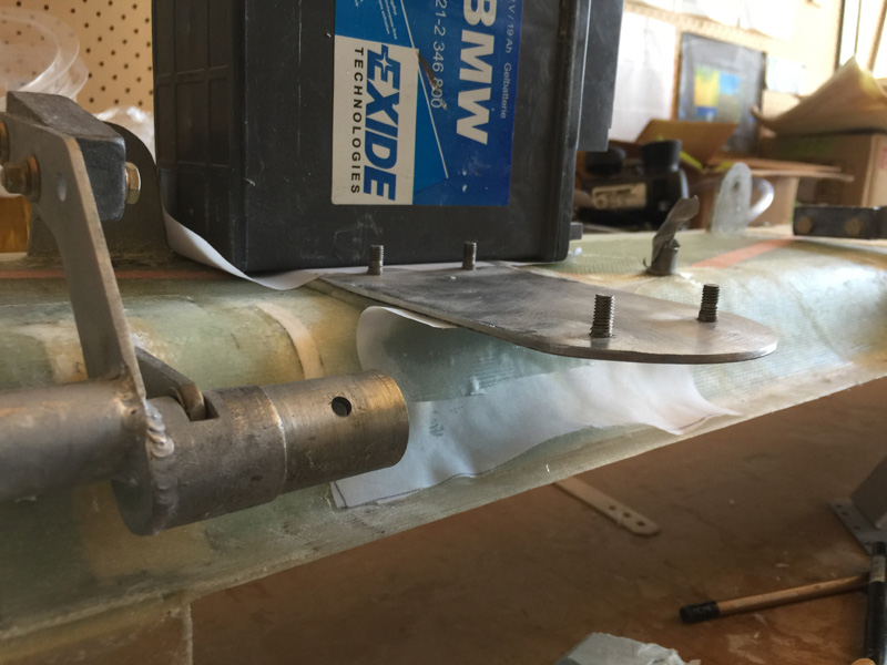
Here’s my base place with the clickbonds ready for fitting after prep work.. The canard is removable, but its a little tricky. I may do a write up in the flight manual on the ‘how’.
I’m using West with flox here and a bit of weight while it cures. That metal MUST clear the torque tube of course. I like West and metal as its just a little less brittle than my usual epoxy. Good for this type of job, and it has a fast hardener.
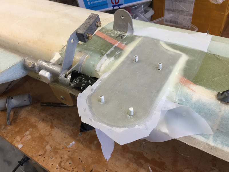
After the Canard to metal cured, I’ve done two ply of BID overlapping onto the canard and one of UND on top. I’ve also added some micro underneath. I’m going to make a support there and shape it so its clear of the torque tube but still adds a little extra strength to that ‘overhang’ with the servo on it.

1 Comment. Leave new
Glad to help! Looks great! 🙂