| Date: 01-07-2020 | |
| Number of Hours: 20 | |
| Manual Reference: 22 |
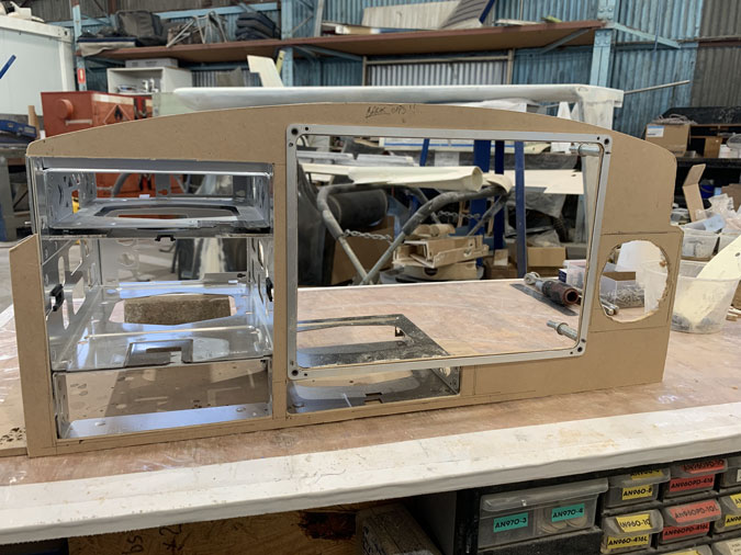
The panel fit out continues.
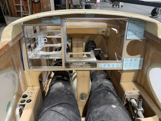
While this is just MDF board so I can see exactly how the panel display is going to work out. There are quite a few tricks to get the parts to fit so closely together. It took a couple of days to get here with some very careful work for something that will be thrown away. That’s the MDF panel, not the trays!
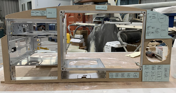
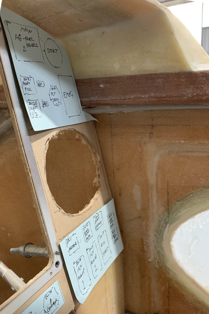
With proof of concept done I then worked on which switches go where. The two AG6 displays I can now see need to be separated. If they were together on the left as I had planned the panel material would have broken off with no thickness left.
The larger rectangles are bigger switch footprint for 10-15amp switches. I now have groupings with the lights below the main panel, engine functions and main bus’s to the bottom right and starter, fuel tank levels, emergency power, alt static and ferry filling right top.
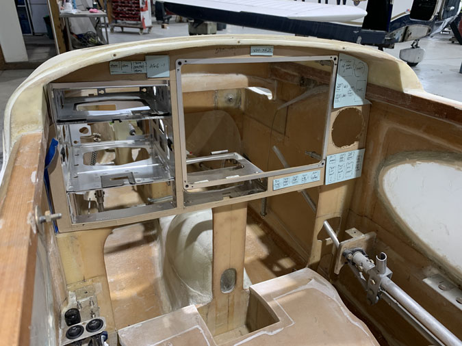
Here’s how it looks in the plane, more or less.
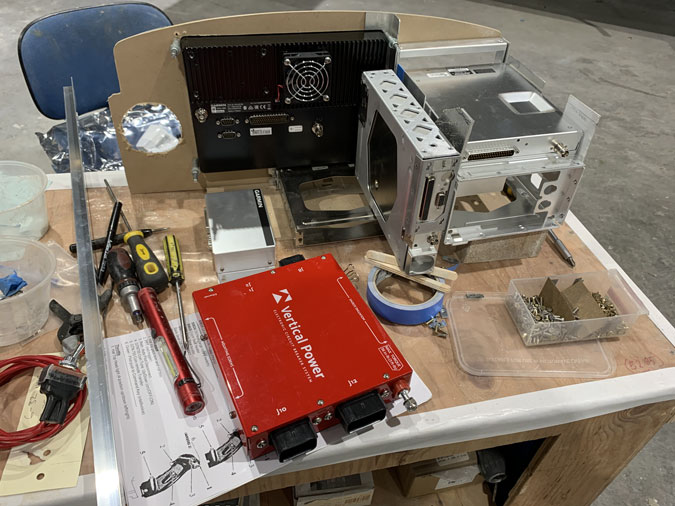
These are only some of the box’s that will go in behind the panel. There are a lot more. I already know that my plans for above the GTN750 case are now changed. I think I have arrived at a way to do all this after spending most of the day trying ideas. Its much easier with things in your hand rather than doing it on paper.
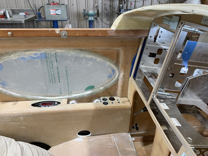
When I put the panel in I found I could give it some angle backwards. Old school steam gauges often mean you need to keep things vertical. A vacuum driven artificial horizon for example will ‘topple’ at a slight angle. I’m a 100% glass cockpit so anything goes.
Here’s an idea of the angle I’m going for.
A look from the other side gives the idea. I will have more of the instruments shielded from the sun with a greater overhang. I’m liking the idea.

1 Comment. Leave new
One step at a time… getting there! Looks like you’re squeezing it all in… 😉
(love those side windows!)