| Date: 11-19-2023 | |
| Number of Hours: 45 | |
| Manual Reference: 23 |
This is a liquid cooled engine, and that means I need a water pump…or two. I thought I had paid for two water pumps from the engine builders. They didn’t come with the engine. After some discussion they sent, along with a few other overlooked items pumps. I thought that one was to be engine driven as discussed but it didn’t happen. Probably electric is better except for the needed electrons.
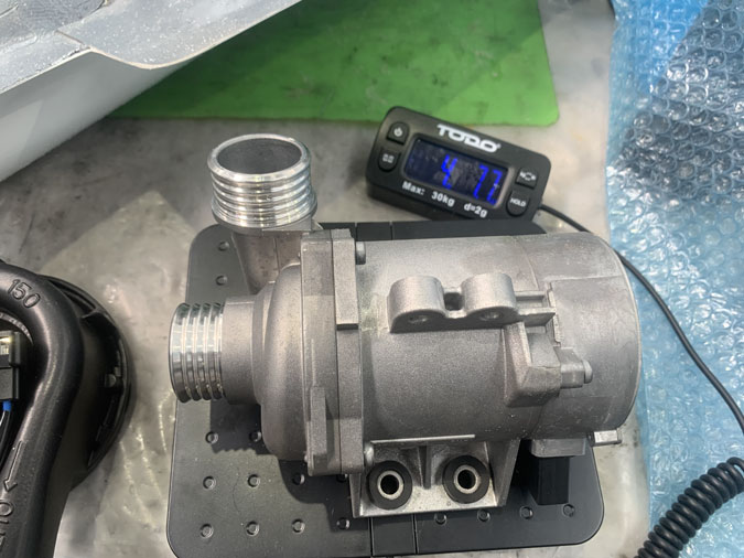
What arrived were two BMW pumps weighing in at 4lbs 7.7ozs each, and they were big. I’m sure they would do the job, but there was no where to put them and I just couldn’t live with the weight penalty.
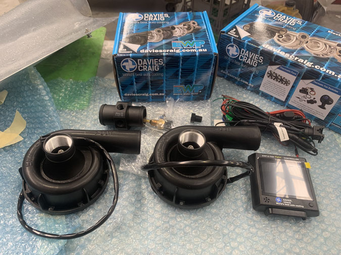
Well, after a few emails and discussion with various people, I ended up buying two Davis Craig EPW150 pumps. These weigh in at 2lbs 10.7oz each almost half the BMW pumps. One has the controller system which covers the pump and any fans. They are rated at 162liters per minute each, although probably less when hot. I need between 100 and 130lts/mt… or so the guesstimate is.
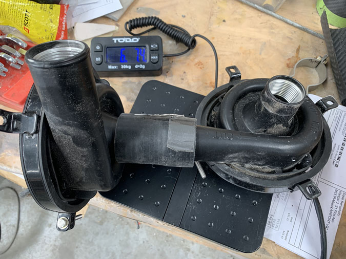
This is the install weight with the joiner and the pump mounts. 6lbs 7.4ozs. Two hose clamps are still to come.
Again, a lot of thought on how to set these up. In the end I decided on plumbing them in series. One pump would have the controller and just adjust itself according to the coolant temperature. The other pump is going to have just an on/off switch. This will be for redundancy and in a pinch, extra cooling.
The issue is already the current draw. These pull around 4amps each and I am right on my 60amp limit. I may even have to load shed to use two pumps at once.
Now where to put these pumps and all that weight?
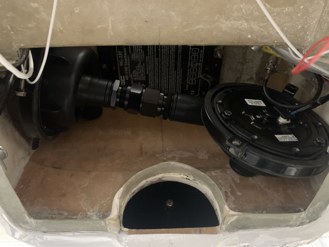
They just did not fit anywhere except in my precious hell hole space. You can see above I had to buy a rather long set of three fittings to join the pumps in series. This is quite a problem. They don’t really fit as you see above and they would be extremely difficult to remove for maintenance as well as taking up space I need. There is a small fitting made that would work well, but it only comes in -12 and these are -16 size.
I looked overseas and found steel fittings, which would rust. I was looking for at least stainless as aluminium was not available anywhere. I negotiated with US companies to send me something but it was all too hard for them to export. I finally found something locally but it was the same size at my initial three joiner fittings and weighted more! So worse than useless..
I gave up and spent $6.95 and got a silicone sleeve that works a treat. The engine designer, Andrew Higgs suggested this. I wanted AN fittings but this sleeve solves the problem to some degree. I will use quality hose clamp fittings. In fact the sleeve allows me to get the pumps closer together than any other solution which gives back a little bit of the precious hell hole space.
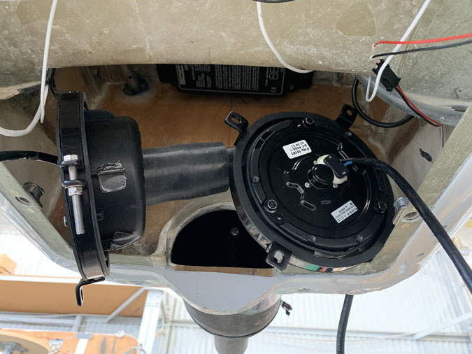
My plan is to mount the pumps on the inside of the hell hole and push them through the firewall without a pass through fitting. I will seal around the pumps with RTV for fire protection. I do like the pumps here, on the plus side I have the 6lbs 7ozs of combined pump as far forward as I can get them,
Even one pump is a LOT of real estate.
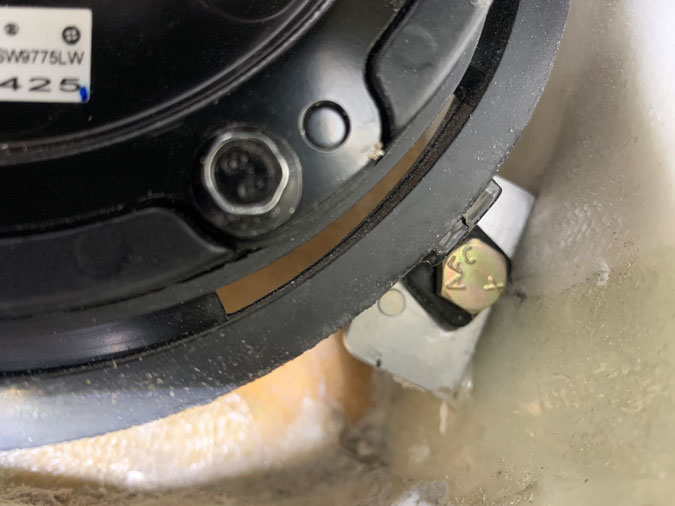
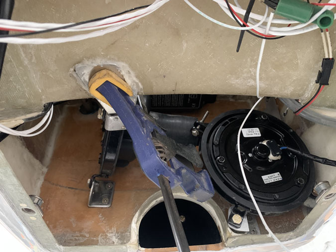
This is where the pumps go. Now I have to somehow mount them like rocks! They are sitting in rubber cradles so all I need to do is hard mount to the ‘front’ or hell hole side of the firewall.
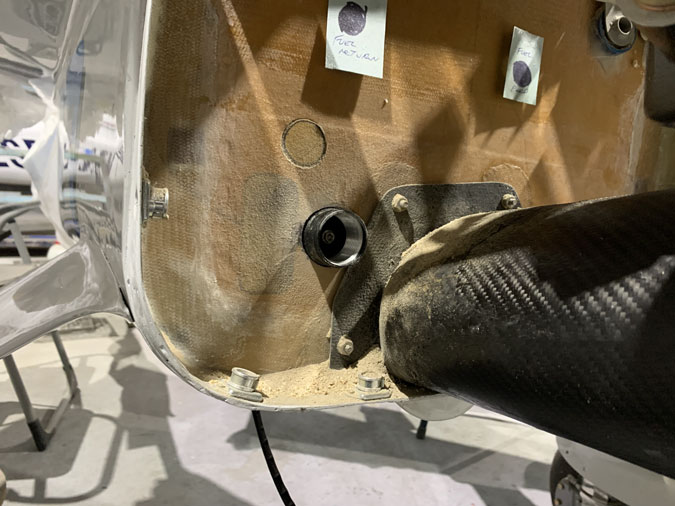
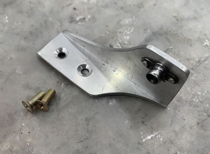
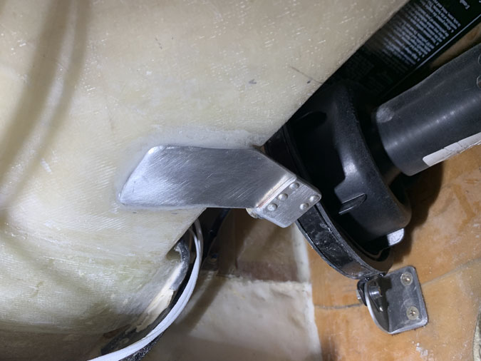
This simple one fitting took a full days work. It is flat aluminium bend on a hand brake at just the right angle. I have glued as well as screwed and used AN4 size fitting for strength. These pumps really …pump so I want very secure mounts.

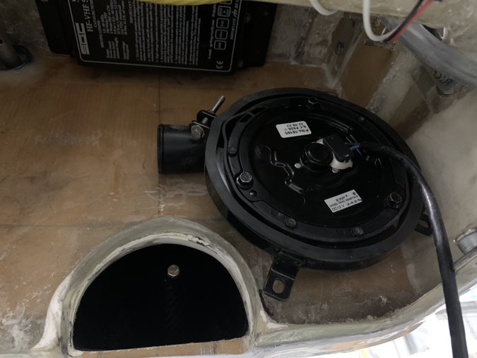
Another days work. No one will see this except me. Again this was bent to an exact fit.
The pumps have to be removable in a ‘relatively’ easy way. This has taken a lot of thought. So now you can see the fruits of two whole days work!
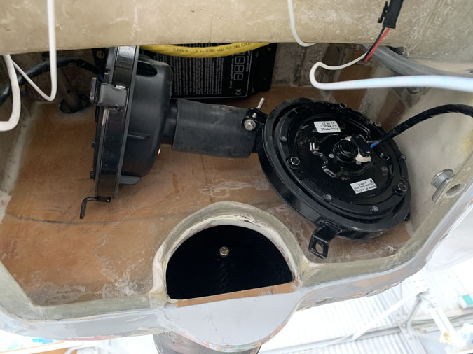
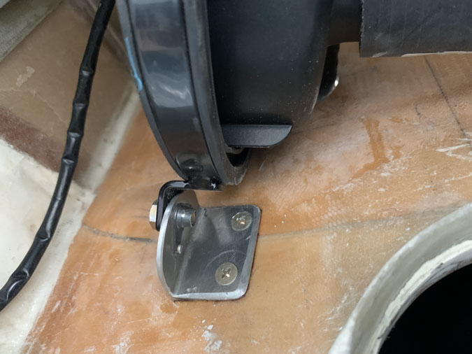
This weird fitting works for the lower corner.
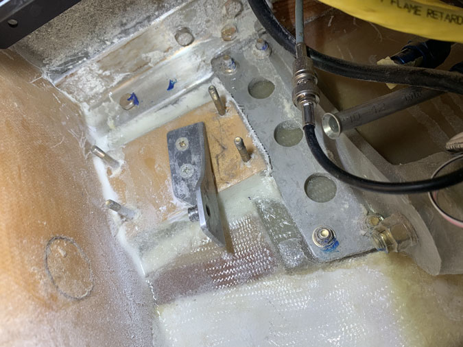
Here we are with the pumps partly mounted. I still have two more on the (photo) right side which are so hard to get to, I need mirrors to even see where to put them.
Here the one I’ve just made for the top right side. I have installed it with glue and followup with adding the screws after cure.
..and here we are, that mount is in place. The long screws you see are where I was going to have an oil pump for heating. It looks like thats not happening now. I’ll leave them in for the moment. I just know if I cut them off…I might have used them for something else.
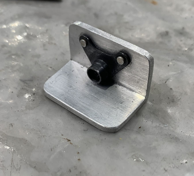
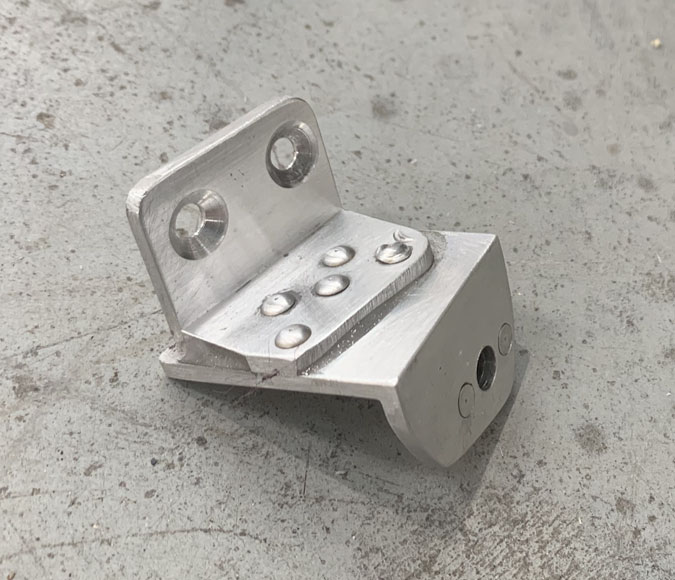
This is the bottom right bracket. Much easier to make than all the others.
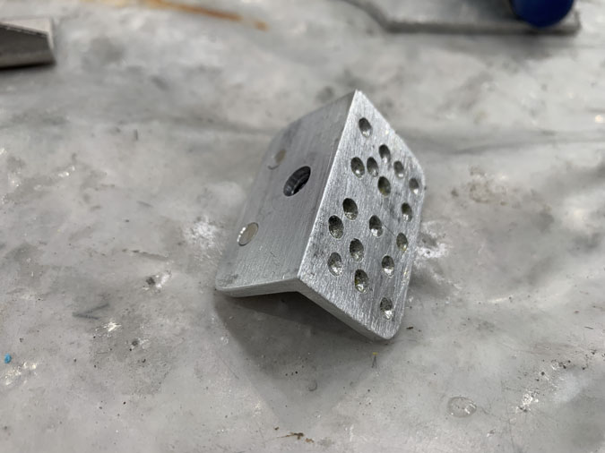
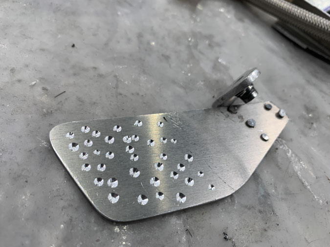
This one will not get screws so as it is floxed in place I’ve added a few dimples to help the glue ‘grab’.
Here’s the bracket in place. Easy to make and really hard to fit! I got it in eventually. After the cure, I’ll take the pumps out and tidy up a bit. I think a little glass might be a good idea on top too. We are not done fitting these pumps yet!
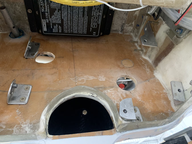
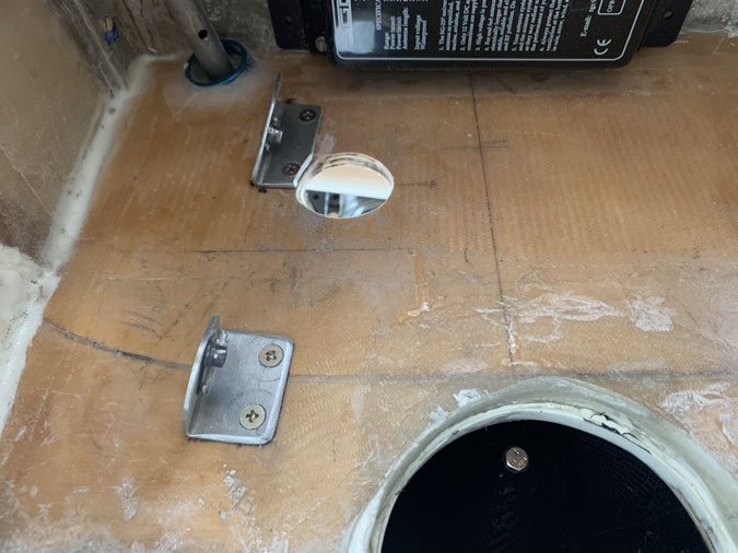
These are the mounts without the pumps. Odd placed for sure but everything fits well. I just have one fitting to go.
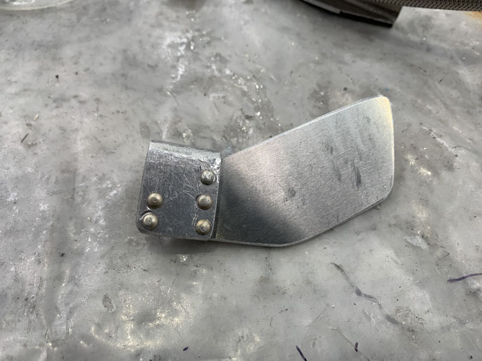
Weird shapes eh? It took a few hours to make this work. The ‘paddle’ has a slight bend to it and the piece with the nut plate was also flat until this afternoon.
After this cures I’m going to clean up and then add a couple of plies of glass for extra strength. A final pic or two will make sense.
Well now this is cured and cleaned up, I’m not going to bother putting glass over the top. It is absolutely rock solid.
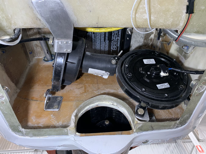
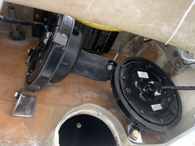
So the two pumps are mounted. I’m happy with this one. Another job done and I can move on to the firewall penetrations now I know what room I have left.