• Home
  • Flying
    • First Flight
  • Build by Chapter
    • Ch 3 Education
    • Ch 4 Fuselage Bulkheads
    • Ch 5 Fuselage Sides
    • Ch 6 Fuselage Assembly
    • Ch 7 Fuselage Exterior
    • Ch 8 Roll Over/Seat Belts
    • Ch 9 Main Gear/Landing Brake
    • Ch 10 Canard
    • Ch 11 Elevators
    • Ch 12 Canard Installation
    • Ch 13 Nose and Nose Gear
    • Ch 14 CenterSection Spar
    • Ch 15 Firewall and Accessories
    • Ch 16 Control System
    • Ch 17 Roll/Pitch Trim System
    • Ch 18 Canopy
    • Ch 19 Wings, Alierons
    • Ch 20 Winglets/Rudders
    • Ch 21 Strakes – Fuel/Baggage
    • Ch 22 Electrical System
    • Ch 23 Engine Installation
    • Ch 24 Covers/Consoles
    • Ch 25 Finishing
    • Ch 26 Upholstry
  • Build Mods
    • Liquid Cooling, Numbers, Weights and Flow
    • Cooling
      • Solving Ground Cooling 1
      • Solving Ground Cooling 2
      • Solving Ground Cooling 3
      • Solving Ground Cooling 4
      • Solving Ground Cooling 5
      • Solving Ground Cooling 6
      • Solving Ground Cooling7 – Test Data
      • Solving Ground Cooling 8 – Flap Building
      • Solving Ground Cooling 9 – Hinges
      • Solving Ground Cooling 10 – Lower Flaps
      • Solving Ground Cooling 11 – Upper Flaps
      • Solving Ground Cooling 12 – Completed
      • Cooling the Beast 1
      • Cooling the Beast 2 – Lower Cowl Expansion
      • Cooling the Beast 3 – KW Oil Cooler Diffuser
    • EVS (Enhanced Vision System)
    • Cowl Keeper
    • Rudder Gust Locks
    • Wing Fences
    • Post Cure
    • Hinge Upgrade
    • RAM Air & Hellhole Cover
    • Main Gear Beef Up
    • Pilot Side Windows
    • Baggage Pods
    • Winglet Intersection Fairings
    • Titanium Rollover
    • Nose Gear Doors
    • Wheel Pants/Gear Leg Fairing
    • Cabin heating System
    • Fuel System
    • Roll and Pitch Trim
    • Oxygen System
    • The Ferry Tank
    • Cruise Angle Indicator
    • Fire Extinguisher Install
  • Round the World
    • RTW Route East #12 rev1
    • Survival Equipment
    • Training Flights
  • Other Stuff
    • Blog
    • Around the World: RAAUS Sport Pilot Issue 110
    • Taxi Tests
    • Summary Feb ’24 from an SAAA Meeting
    • AOPA Pilot 27th Sept 2019
    • Build Tests
    • Flying Stories
      • A Long Easy Dream ’06
      • Townsville ’07
      • Cairns ’08
      • Albany ’08
      • East Coast ’08
      • Brisbane ’09
      • Cairns ’10
      • Perth ’10
    • Non Build Mods
      • F16 Scoop for JZE
      • Ram Air Box for JZE
      • Strange Tips
    • Milestones
    • Links
  • Contact

Blog

Home
Blog
Making, Testing and Fitting Fuel Hoses 2

Making, Testing and Fitting Fuel Hoses 2

1 year ago
Dave Berenholtz
Blog, Ch 23 Engine Installation
Date:  12-23-2023
Number of Hours:  22
Manual Reference:  23

There is a bit going on here. As I continue this hose business I’m covering a few ‘hold down’ tasks. If not now…when?

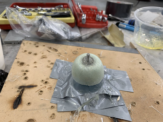
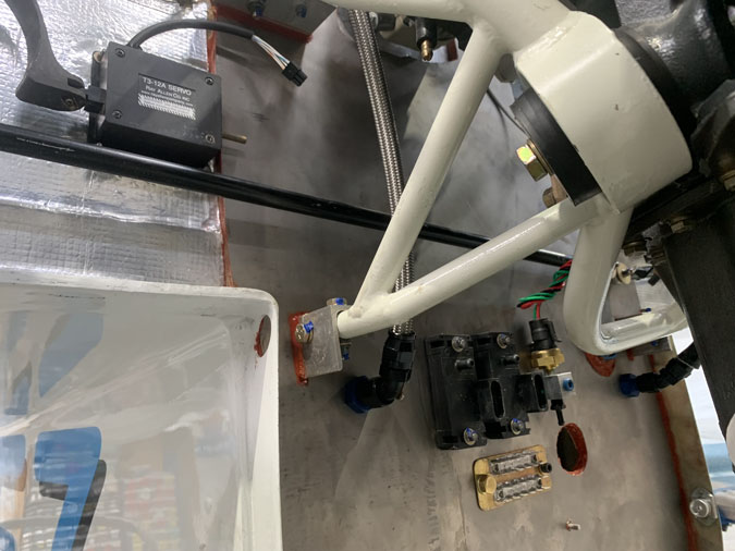
The left side cockpit return line fuel hose seems to hang in mid air so it needed a standoff that allows the hose to remain straight. This is a piece of blue foam carved to shape with a click bond on top and then two plies of glass.

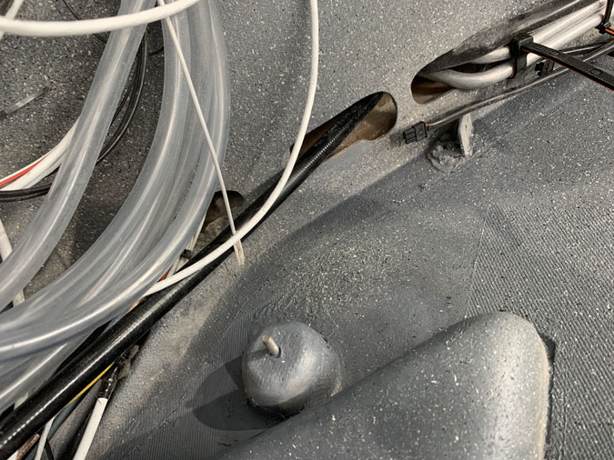
After a bit it was bonded to the side which had paint removed first of course. Some glass around the base and then a little grey paint.

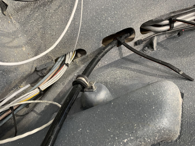
While obviously not done up you can see a good fit for the P clamp and then I did two slots at the end for a rubber faced reusable cable clamp. This was the easy side. On the right I’m still thinking how to do it with the main power cables, control pushrod, wiring and other stuff all in the same place.

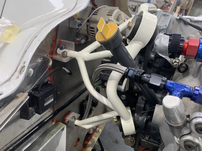
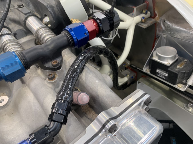
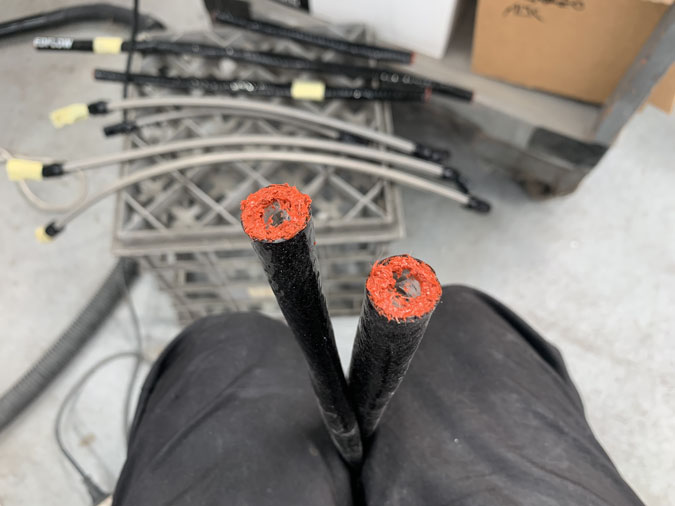
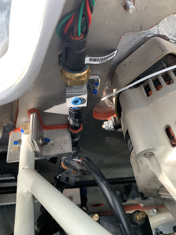
I have gone to quite some trouble to get the right fittings for these hoses. Above is a regular straight fit.

This lower fitting is angled. There are 30, 45 and 90 degree options in this ‘Speedflow 200’ line.  While they are not cheap, its a tidy way to minimise the bends in the hoses as much as possible. Teflon lined, these guys don’t like to bend too much, unlike the all rubber type. Keeping the fuel (or air) flows as smooth as possible with minimal sudden direction changes is also a goal with this install.

Again more trial fitting, this time with the fire protection cut to size.

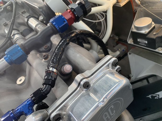
This joins the two banks of injectors. I’ll be using standoffs and whatever works to secure the lines every 6 inches or so.

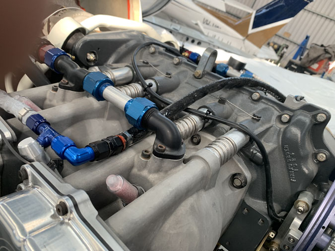
I don’t like how the hose is almost sitting on the engine here. I might add some rubber or the RTV impregnated glass I’ve made up for this sort of thing and sit it over the fittings.

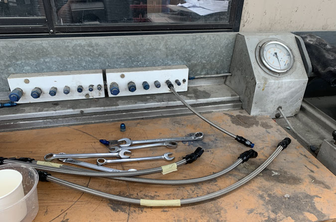
Now this batch of hoses are sized and all the ends fitted they need to be tested. Again I went to 1000psi for at least 60 seconds on each hose. They are all fine.

I tried to get the special aviation dip for sealing the fire sleeve ends but none was available. I am NOT buying a few hundred dollars worth of stuff to only dip 8 ends. RTV will have to do.

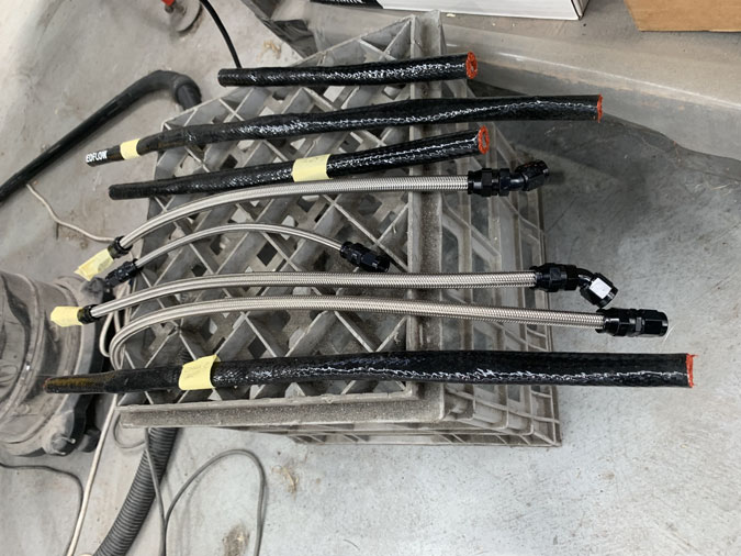
Ready for installation.

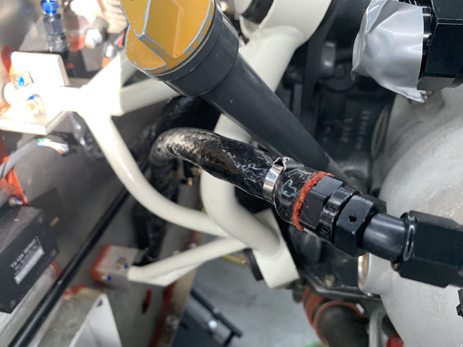
Here I’ve added stainless steel straps to secure the fire sleeves. This was a bit of fiddling around and I did buy a special tool. The type of straps I ended up with self lock. So like a cable tie as you pull it through they say put. I just needed to get them tight or lets say, ‘firm’ and then cut the ends off. I gave  a few hammer taps where the ends were just to make the sharp end sit down.

You can see here how I looped around the spark plug to ensure access.

This is a bit hard to see but it was SUPER hard to connect at the engine end. There is a restriction fitting on the -4 line right next to the left top engine mount. Connecting it was a few hours including reshaping a spanner to a minimum head size!  In the end I took off the ignition block. That then gave access, I should have started with that in the first place.

This sensor is for oil pressure to the G3X. A lot of mucking around required! You can’t quite see where it goes on the engine. To see it you really need to take the engine off and I’m not doing that for you. Sorry!


Previous Post
Making and Testing Fuel Hoses 1
Next Post
Alternator Cover Revisited

Leave a Reply Cancel reply

Your email address will not be published. Required fields are marked *

Fill out this field
Fill out this field
Please enter a valid email address.

CategoryLogsHours
All157617079
Uncategorized135
Ch 3 Education220
Ch 4 Fuselage Bulkheads25231
Ch 5 Fuselage Sides32283
Ch 6 Fuselage Assembly30270
Ch 7 Fuselage Exterior14140
Ch 8 Roll Over/Seat Belts990
Ch 9 Main Gear/Landing Brake71642
Ch 10 Canard28287
Ch 11 Elevators36298
Ch 12 Canard Installation12102
Ch 13 Nose and Nose Gear1291097
Ch 14 CenterSection Spar57525
Ch 15 Firewall and Accessories448
Ch 16 Control System27237
Ch 17 Roll/Pitch Trim System654
Ch 18 Canopy70502
Ch 19 Wings, Alierons1271090
Ch 20 Winglets/Rudders71528
Ch 21 Strakes - Fuel/Baggage65437
Ch 22 Electrical System591031
Ch 23 Engine Installation961152
Ch 24 Covers/Fairings/Consoles25202
Ch 25 Finishing561084
Ch 26 Upholstry340
Fuel System46310
Rollover1050
Cabin heating System60331
The Ferry Tank335
Blog2694182
Build Mods2252513
Nose Gear Doors856
Wheel Pants/Gear Leg Fairing40473
Oxygen System762
Roll and Pitch Trim964
Winglet Intersection Fairings445
Baggage Pods11104
Pilot Side Windows437
RAM Air & Hellhole Cover15177
Main Gear Beef Up322
Post Cure124
Fire Extinguisher16
Wing Fences13
EVS (Enhanced Visual System)130
Hinge Upgrade115
Cowl Keeper110
Rudder Gust Locks19
Cooling20607
Taxi Tests42
Flying10

Complete the Test Flight Program

2025/6/30 10:26:01

Round Australia in Four Flights

2026/4/1 10:26:01

Round the World Departure

2026/8/22 10:26:01

Rough River Flyin, Sept 23, 2026

2026/9/23 10:26:01

© Copyright 2025 Dave Berenholtz