| Date: 05-05-2017 | |
| Number of Hours: 5 | |
| Manual Reference: no ref |
I suppose this counts as build hours as I made some cardboard bits. Having spent some time working out the control positions on the right side it was time for decisions on how and where the sump feed from the wing tanks was going to happen.
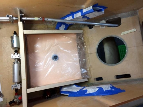
I’m going to have to make my own pipes. I’ve been thinking for a while about how to do this and I might try to make some molds out of clay. I did do a cardboard mock-up as you can see which took a lot longer than you’d think! I want around 4 sq” feeding the tanks so they equalise from one side very quickly. What I have mocked up will work OK around the controls and fuel lines. I did need to see how it all worked so I can plan items like the regulator and where wire runs might go.
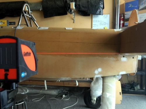
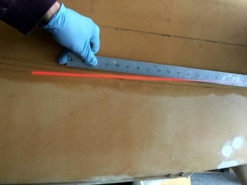
Another thing was where to put the outlets from the wing tanks. Plans have them right in the aft inboard corner but I have curved bottom strakes. In pics 1 & 2 I have jacked up the nose to 2 degrees… where it will be in flight and had a really good think about low fuel situations relative to the pickups. That said I will have 14 liters in the common sump as my low point and very little unusable fuel.
The laser lines suggested that this tank low point was just a bit more forward than plans. Then I had to account for the back seat belt position too for where my homemade pipes will go. They will be as pictured. (pic 3)
2 degree nose up fuel line
Checking for the low point
Mock up in place


