• Home
  • Flying
    • First Flight
  • Build by Chapter
    • Ch 3 Education
    • Ch 4 Fuselage Bulkheads
    • Ch 5 Fuselage Sides
    • Ch 6 Fuselage Assembly
    • Ch 7 Fuselage Exterior
    • Ch 8 Roll Over/Seat Belts
    • Ch 9 Main Gear/Landing Brake
    • Ch 10 Canard
    • Ch 11 Elevators
    • Ch 12 Canard Installation
    • Ch 13 Nose and Nose Gear
    • Ch 14 CenterSection Spar
    • Ch 15 Firewall and Accessories
    • Ch 16 Control System
    • Ch 17 Roll/Pitch Trim System
    • Ch 18 Canopy
    • Ch 19 Wings, Alierons
    • Ch 20 Winglets/Rudders
    • Ch 21 Strakes – Fuel/Baggage
    • Ch 22 Electrical System
    • Ch 23 Engine Installation
    • Ch 24 Covers/Consoles
    • Ch 25 Finishing
    • Ch 26 Upholstry
  • Build Mods
    • Liquid Cooling, Numbers, Weights and Flow
    • Cooling
      • Solving Ground Cooling 1
      • Solving Ground Cooling 2
      • Solving Ground Cooling 3
      • Solving Ground Cooling 4
      • Solving Ground Cooling 5
      • Solving Ground Cooling 6
      • Solving Ground Cooling7 – Test Data
      • Solving Ground Cooling 8 – Flap Building
      • Solving Ground Cooling 9 – Hinges
      • Solving Ground Cooling 10 – Lower Flaps
      • Solving Ground Cooling 11 – Upper Flaps
      • Solving Ground Cooling 12 – Completed
      • Cooling the Beast 1
      • Cooling the Beast 2 – Lower Cowl Expansion
      • Cooling the Beast 3 – KW Oil Cooler Diffuser
    • EVS (Enhanced Vision System)
    • Cowl Keeper
    • Rudder Gust Locks
    • Wing Fences
    • Post Cure
    • Hinge Upgrade
    • RAM Air & Hellhole Cover
    • Main Gear Beef Up
    • Pilot Side Windows
    • Baggage Pods
    • Winglet Intersection Fairings
    • Titanium Rollover
    • Nose Gear Doors
    • Wheel Pants/Gear Leg Fairing
    • Cabin heating System
    • Fuel System
    • Roll and Pitch Trim
    • Oxygen System
    • The Ferry Tank
    • Cruise Angle Indicator
    • Fire Extinguisher Install
  • Round the World
    • RTW Route East #12 rev1
    • Survival Equipment
    • Training Flights
  • Other Stuff
    • Blog
    • Around the World: RAAUS Sport Pilot Issue 110
    • Taxi Tests
    • Summary Feb ’24 from an SAAA Meeting
    • AOPA Pilot 27th Sept 2019
    • Build Tests
    • Flying Stories
      • A Long Easy Dream ’06
      • Townsville ’07
      • Cairns ’08
      • Albany ’08
      • East Coast ’08
      • Brisbane ’09
      • Cairns ’10
      • Perth ’10
    • Non Build Mods
      • F16 Scoop for JZE
      • Ram Air Box for JZE
      • Strange Tips
    • Milestones
    • Links
  • Contact

Blog

Home
Blog
Exhaust Pipes Ceramic ‘Jet’ Coating, Support Refit and Sensor Installs

Exhaust Pipes Ceramic ‘Jet’ Coating, Support Refit and Sensor Installs

1 year ago
Dave Berenholtz
Blog, Ch 23 Engine Installation
Date:  05-09-2024
Number of Hours:  10
Manual Reference:  23

Ceramic coating, done properly, can reduce heat from the exhausts under the cowls by 30%. I want that heat out the pipes not adding to the cooling problems all ‘pusher’ canards seem to have.

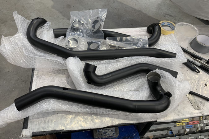
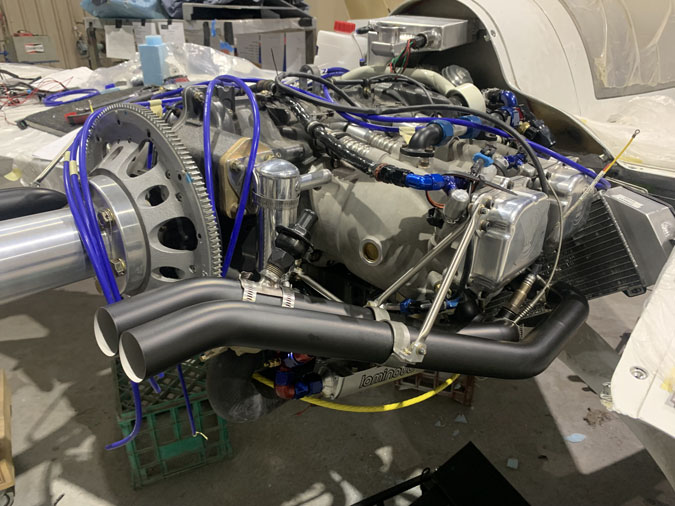
This coating is called HP2 Black and was done by HPC (High Performance Coatings) in Leongatha, Victoria, Australia. Turnaround was about two weeks and the coats very reasonable. The job is as good as it looks. I now have to be very careful with the pipes as they will scratch more than bare chrome moly steel.

I got the pipes in and this time with the correct Lycoming steel gaskets and did the nuts up to spec as best I could. I did buy a new offset Snap-on 1/2″ spanner as the pipe nuts are always a wrestling match. I could torque a couple of them to spec and the others had to be by feel. I have no idea how you get a torque wrench on some of them them.

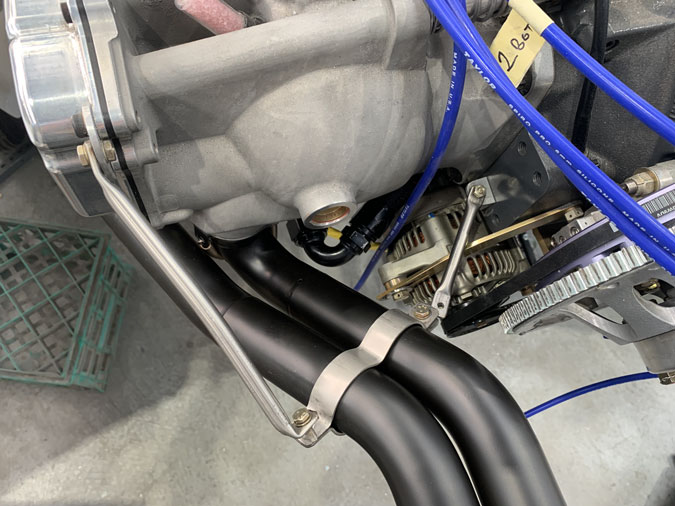
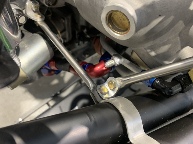
Notice the difference? Yeah, that right angle bend I’d made on the pipe support was going to crack one day. Since making these supports my ideas have evolved a little and using a good 2024-T3 bit of angle as a bracket is likely to last longer. So all those initial supports were replaced. I am much faster doing this work the second time around.

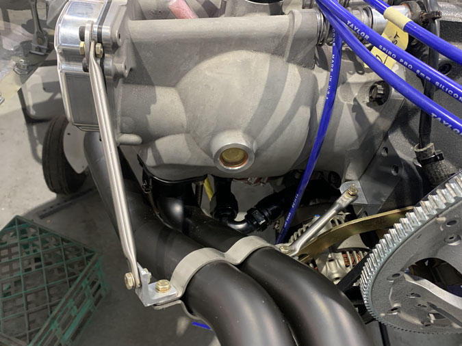
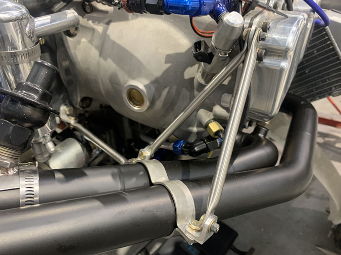
I redid this one too. The way the bracket on the engine is now is can’t rotate easily and it now clears the alternator support arm by a good margin although its hard to see from this angle. It was too close before.

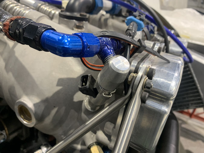
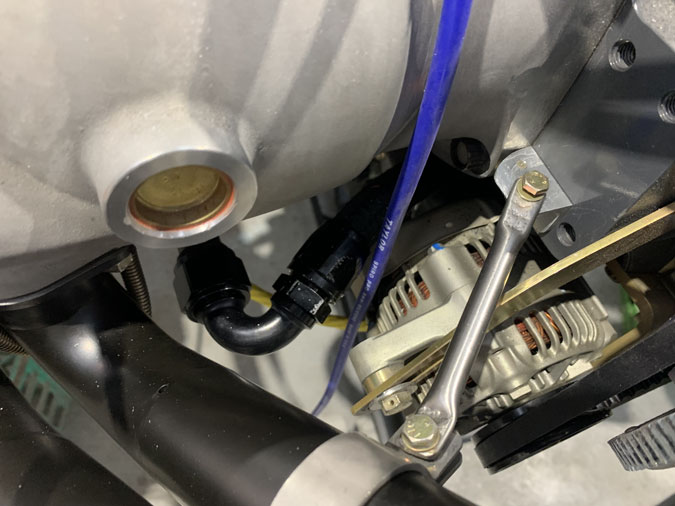
I did improve the clearance here slightly but there is not much I can do about the bend. The support needs to clear the injector. Other methods just introduce alternate problems of a similar magnitude. All my stainless steel supports along with other items will get regular inspections as a part of my maintaining duties.

This one was certainly improved with a bracket instead of a tight bend.

Not exactly elegant but I hope very strong on this outside join. Maybe I will round the corners to make it look nicer. For now, its just keep going.

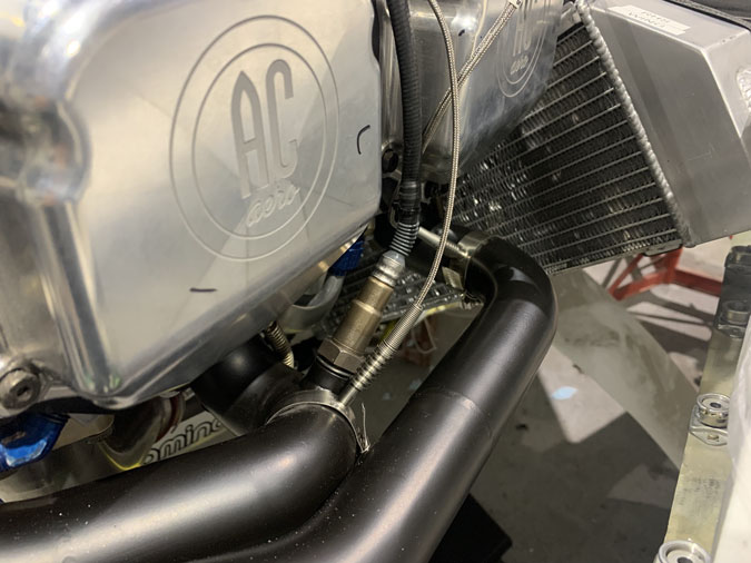
I had pre-drilled holes and had that boss for the air fuel ratio sensor welded on before the coating. Looking back I might have gotten the screw in type EGT’s. Maybe on the next plane HA!  They are all in about 2.5″ down from the outlets. While it was just four simple holes I did a while ago, I was very careful to try and ensure the sensors were clear of the pipes, cowls and access to the spark plugs.

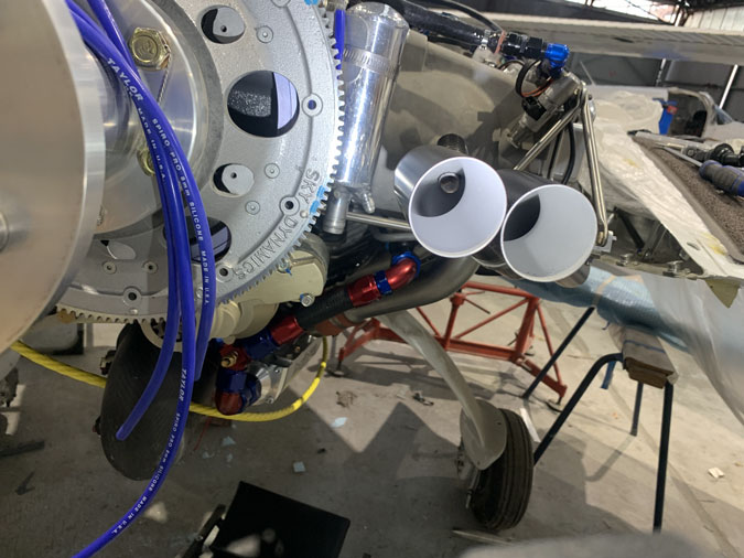
The pipes look lean already on the inside. You can see the outlet from the crankcase negative pressure pipe which is a part of the oil separator setup. This should further reduce oil losses in flight and keep things happier in the engine. It also adds another maintaining item as that pipe MUST be clear of buildup. Its a 50 hourly check although initially I will do it more often and see what buildup is occurring, if any.

Here’s a bit of an overview. It is going to look messy until I get all the wires back on, connected and secured.

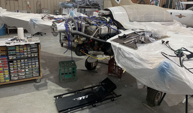
Another overview of my work area.


Previous Post
LHS Radiator Duct 1
Next Post
Overflow Bottle Install

Leave a Reply Cancel reply

Your email address will not be published. Required fields are marked *

Fill out this field
Fill out this field
Please enter a valid email address.

CategoryLogsHours
All157617079
Uncategorized135
Ch 3 Education220
Ch 4 Fuselage Bulkheads25231
Ch 5 Fuselage Sides32283
Ch 6 Fuselage Assembly30270
Ch 7 Fuselage Exterior14140
Ch 8 Roll Over/Seat Belts990
Ch 9 Main Gear/Landing Brake71642
Ch 10 Canard28287
Ch 11 Elevators36298
Ch 12 Canard Installation12102
Ch 13 Nose and Nose Gear1291097
Ch 14 CenterSection Spar57525
Ch 15 Firewall and Accessories448
Ch 16 Control System27237
Ch 17 Roll/Pitch Trim System654
Ch 18 Canopy70502
Ch 19 Wings, Alierons1271090
Ch 20 Winglets/Rudders71528
Ch 21 Strakes - Fuel/Baggage65437
Ch 22 Electrical System591031
Ch 23 Engine Installation961152
Ch 24 Covers/Fairings/Consoles25202
Ch 25 Finishing561084
Ch 26 Upholstry340
Fuel System46310
Rollover1050
Cabin heating System60331
The Ferry Tank335
Blog2694182
Build Mods2252513
Nose Gear Doors856
Wheel Pants/Gear Leg Fairing40473
Oxygen System762
Roll and Pitch Trim964
Winglet Intersection Fairings445
Baggage Pods11104
Pilot Side Windows437
RAM Air & Hellhole Cover15177
Main Gear Beef Up322
Post Cure124
Fire Extinguisher16
Wing Fences13
EVS (Enhanced Visual System)130
Hinge Upgrade115
Cowl Keeper110
Rudder Gust Locks19
Cooling20607
Taxi Tests42
Flying10

Complete the Test Flight Program

2025/6/30 10:26:01

Round Australia in Four Flights

2026/4/1 10:26:01

Round the World Departure

2026/8/22 10:26:01

Rough River Flyin, Sept 23, 2026

2026/9/23 10:26:01

© Copyright 2025 Dave Berenholtz