| Date: 12-19-2025 | |
| Number of Hours: 0 | |
| Manual Reference: 23 |
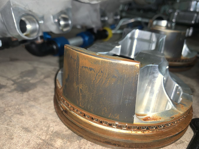
As I explained in the post ‘‘engine-rebuild-1‘ the engine became so tight I couldn’t start it. Its been to the engine shop and lived there for five months. This puts my circumnavigation plans back until 2027 now. First up they ‘pulled the jugs’ or in plain speak, removed the cylinders.
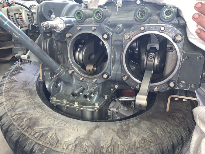
As it turned out the ‘bottom end’ of the engine was perfect, no rust, no problems. Nothing to see here. That was good news as I was expecting a bulk strip with a rusty camshaft and who know what else.
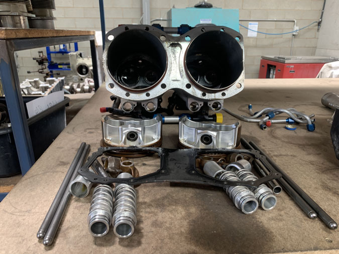
In the cylinders things weren’t too bad either.
A tiny bit of surface pitting but of no concern.
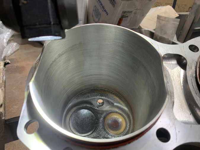
The bores only needed a light hone with the ‘dunny brush’ and the valves were no problem. This shot is after the work with a lot of preservation oil. The cylinders were not glazed either so run-in or break-in worked out OK.
Eeeerrrkkk!!
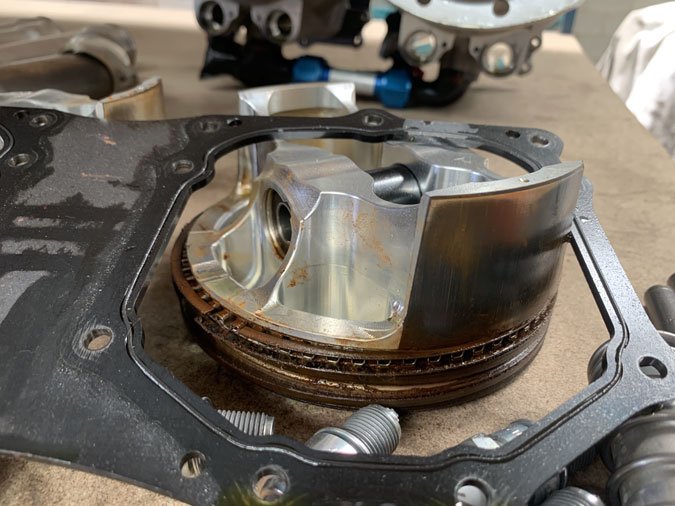
The rings however….
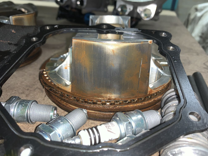
Huge amounts of rust at the rings, locking them solid.
Even after a clean up these are not so pretty.
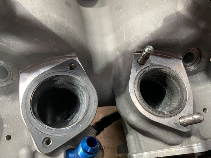
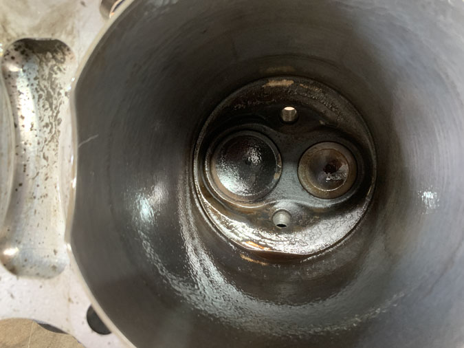
There was also corrosion just at these intake ports but not down the tubes. It was confided just to the heads area.
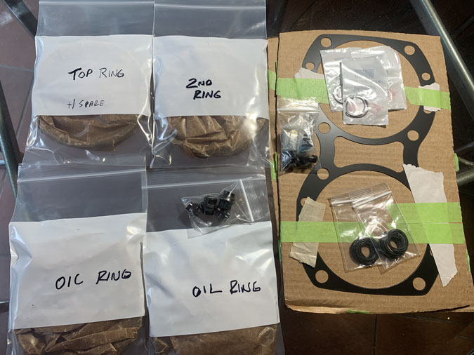
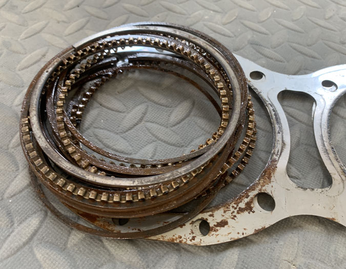
New rings were of course required. These came from the engine builders in the USA.
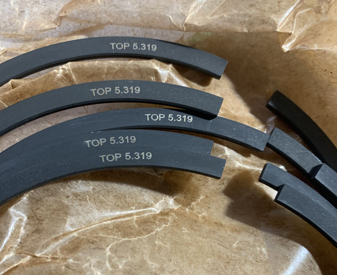
They don’t seem to be a standard part, they are different to the old rings. The top ones have TOP 5.319 which would be the bore size. I have 390 cylinders, I assume bored out, and oversized pistons given they are marked with xx.
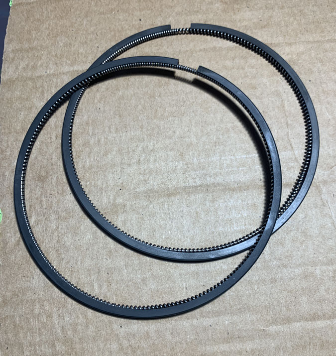
The oil rings have no markings. The following is what was sent to help the install and I’ve put it here so I have a permanent record in an easy to find place.
Here is some specs. *Cylinder base nut torque spec. Lube the threads and the matting surfaces of the spherical nut generously with Carrillo bolt lube I sent you I can take a pic for reference, use the Lycoming torque sequence but using our final torque value of 60 ft pounds on the 1/2″ and 32.5 ft pounds on 3/8″ studs. Make sure you torque wrench is 90° to the engine vertical centerline as its super easy with base wrenches and the higher value to cover torque as they are always in a awkward area its not near aa easy as a regular Lycoming.
*Pistons are directional I will send a diagram so you can confirm nothing gets flip flopped.
*Piston rings must be installed using a ring expander if you try to roll the piston rings on you will very potentially experience ring issue or micro welding as the ring side clearance is tight and the square ring desing will damage the groove, always oil the rings and grooves before install, make sure the ring rotates freely in the groove while compressing the ring slightly. Stagger rings 180° so staring at the piston the ring end gap will be top ring 12:00. 2nd 6:00 and then I do the oil at 11:00 or 1:00 just slightly offset from 12:00. Top Ring end gap. .029″-.044″ 2nd Ring end gap. .029″-.047″ (2nd ring should be .0025″ to .0045″ larger than the top ring gap Oil Ring end gap. Min .020″ These values fall in spec but for your build I would not open them up if they are above the minimum value and I already added .0035″ to the 2nd rings chances are you will not have to touch them but must confirm.
*cylinder honing notes. I don’t know if they need to touch them up but they can’t go too big on the cylinders they will have to check the dimensions. If they do hone they need to target for a rvk 80 and a rpk under 10 are the 2 most important values. Hopefully they have a profilometer maybe confirm with them so they can check surface finish, its very critical. One other thing to note the ring goes right to the top of the sleeve like .020″ from the top so very close there is an additional. 070″ of room before they crash into the head, they should have no issue with this unless their is a tooling clearence problem but its worth noting as its not typically how lycoming does it they normally have tons of room. Piston to cylinder wall clearence is .0065″ to .012″ If they struggle on the hone we could always resleeve your cylinders if needed.
*A thin base shim gasket was shipped that will be installed on the cylinder first then your standard lycoming o-rings. The engine deck surface and cylinder surface must be extremely clean and dry before install, a grey scotch brite pad is ok to clean up little scratches or debris, teeat it like a automotive head gasket instal no nics or high spots, from scratches, ect. Clean and dry. Will send pic for install reference.
*Cylinder install. We need to talk about this before done as very critical and easy to mess up critical components if not done right, I can discuss procedures that will make it easier and less likely to cause any damage but here is overview so you have an idea of what is required. when installing the cylinders on the plane we will talk first. During the procedure its very easy for the cylinder to rick and for the skirts to hit the studs so extreme caution is needed, but need a smooth flat surface that is level to the crank and can set height right (I can send pics and will discuss more as this sets you up most for success, failure, or just pulling your hair out! Lol), remove the lower coolant fittings with the 2 allen bolts so it sits flat on the surface, load the pistons with inner clips already installed and push them in to wear the wrist pins can slide in still in the relief cuts so once the oil ring is in just a hair further, the rotate the engine to where the rear ro is highest up then install wrist pin and clip, rotate so you instal the front wrist pin and clip then push cylinder on and follow lycoming torque sequence for thru bolts not single cylinder. (Can send diagram for sequence if needed) Thanks and keep me posted and I will send you a few diagrams on the torque spec, piston orientation, etc.
These are the instructions verbatim. Nothing further was sent. The engine shop back here in Australia were happy to go ahead and are very confident the engine is correctly back together.
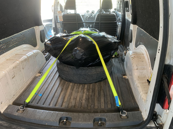
I was very please to get the engine back to the van for transportation. It was a mammoth day with 10 hours driving to get it to my hangar.
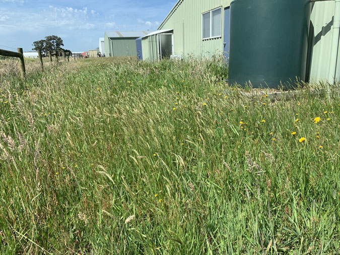
I mowed the lawn on my last trip, so this is 5 months growth while the engine was getting a new set of rings. The shop here have great people and do quality work but they can’t find more staff so things take a crazy amount of time to get done. I am both grateful and frustrated at the same time.
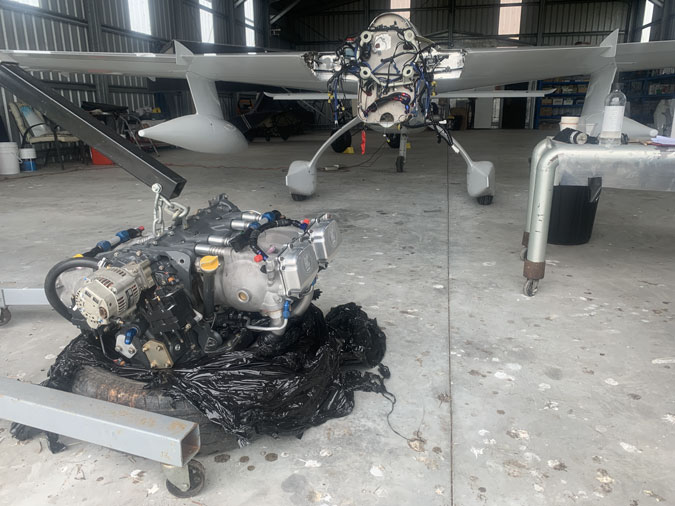
Back to business, the reinstall is proving to be an enormous job with a lot of challenges. I’ll update all this in another post.
What happened to the engine? Why did the Rings rust?
Haaa we are finally here. Water causes rust. My coolant level hasn’t moved during the test flying. There are no cracks in each cylinder and they all had similar amounts of ring rust. This rust is confided to the heads.
The rust got WORSE the more I flew. That’s crazy. It got so bad that the engine became harder and harder to start until is didn’t. The rust was stopping the rings from moving and they were catching in the bore as I tried to crank the starter. No dice.
A borescope confirmed terrible rust after the ‘no start’ that was not present at the beginning of the test flying. I did a check before the program began. We had a little surface rust initially but it diminished with ground runs and a couple of oil changes and filter cleans. I was always concerned about the engine tightness from Day 1, perhaps this is not the worse thing that could have happened.
Condensation! (or Sweating)
Yeap. It must be producing water from the atmosphere that runs down the cylinders and collects on the rings. For ‘break-in’ I use Aeroshell 100 straight mineral oil and that has no ‘detergents’ or rust inhibitors, so we have no corrosion protection either.
I believe when warm, moist air comes into contact with a cold surface, the air right at that surface cools down. Since cooler air can’t hold as much water vapor as warm air, the excess moisture condenses into liquid water droplets on that surface. As best I can tell it depends on the dew point or humidity at the time as to how much or little temperature difference (DeltaT) can cause the problem. Probably around 20-40F gap would be enough to give me this very expensive situation. That’s not much at all.
With my cooling flaps open after landing, given under the cowls would be heat soaked, I now produce a rapidly cooling surface while my coolant at 160-200F stays much warmer. So I get a temperature mismatch. My rapidly cooled external cylinder surfaces drop below the dew point of the surrounding hot engine bay air = sweating.
This also produced the 5 month gap in my program (as I keep saying) and I’m already another month gone in getting the reinstall started. I might be flying again in February 2026. Then I have to bed the rings in which might be 20-40 hours before I can resume the test program.
I think I might leave the cowl flaps closed after landing now! Maybe lean out the engine then and be in no hurry to shut down. Its a plan. Once the run in is completed I’m thinking Camguard oil additive might be good too when I go to the Aeroshell 15W50 Oil or something similar.