| Date: 12-19-2021 | |
| Number of Hours: 0 | |
| Manual Reference: no ref |

 It is time to begin documenting my cooling systems for the engine. I’m treating this as a modification as this plane will have liquid rather than air cooling for the cylinders.
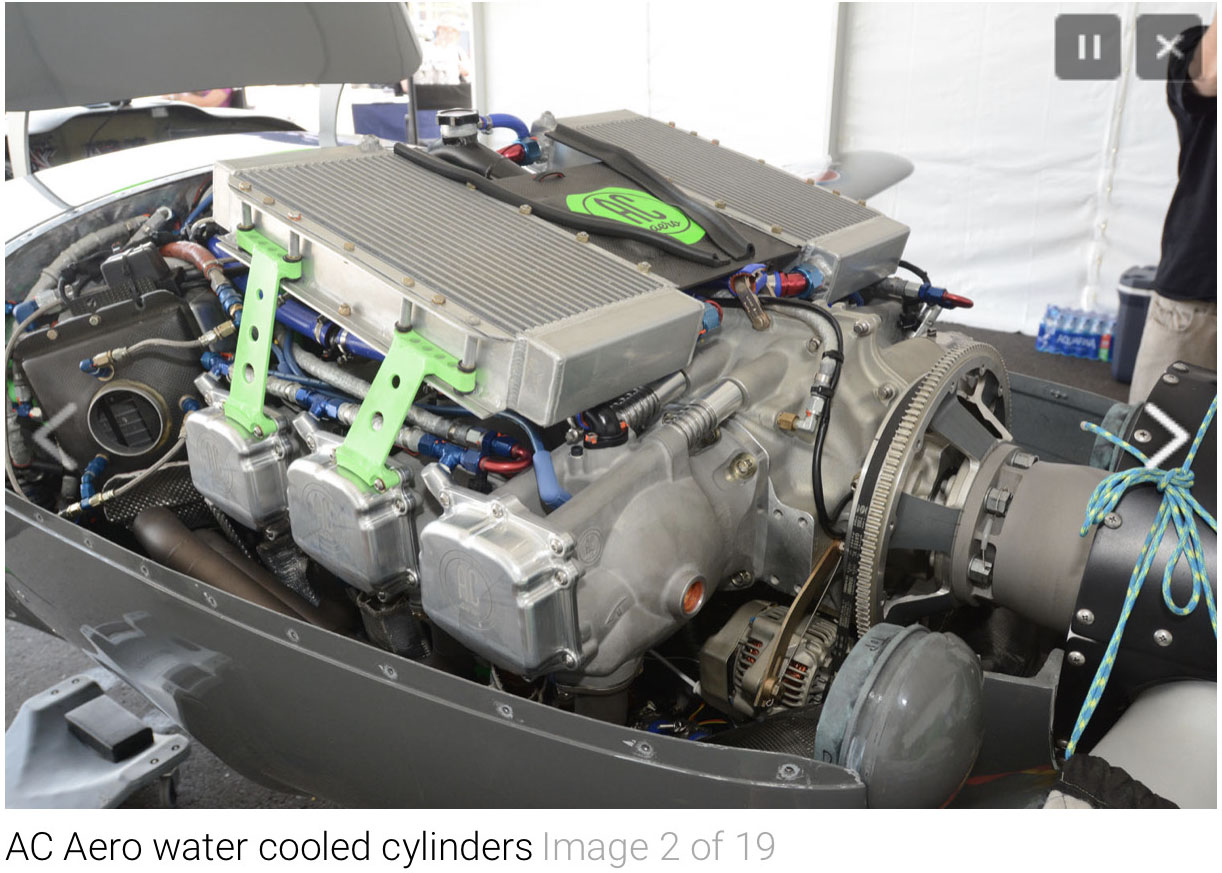
The engine will be an AC-Aero Gladiator X440. It should be delivered March 2022.
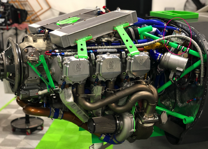
This is a six cylinder version with a turbo and 1000HP. Mine will be 300HP, four cylinders and normally aspirated. Think of a Lycoming 0-360 angle valve stroked out to 440 cubic inches and with liquid cooling via special cylinders. The big challenge is fitting radiators under my tight cowls.
Lets go back to basics to determine how much heat I have to get rid of.
1). 1 Horsepower = 2544.43 BTU/hr or 42.4 BTU/min.
One Btu is the amount of heat required to raise one pound of water by one degree Fahrenheit. …
2). Roughly 1/3 of an engine’s BTUs ends up in the cooling system
3). Therefore, roughly 14.12 BTU/min per HP ends up in the cooling system. (42.4/3=14.12BTU/min HP)
4). This is where it gets even sketchier yet – In a single row efficient aluminium radiator, each cubic inch will cool approximately 11 BTUs (therefore, BTU/11 = approximate cubic inch of single row radiator).
5). Assuming that your single row radiator is 2” thick, then each sq in of radiator frontal area would cool approximately 22 BTUs (therefore, BTU / 22 = approximate sq in of single row radiator).
6). Approx BTU requirements 300HP X 42.4 BTU/min X 1/3 = 4,236 BTU/min.
So we need 4236 a minute with a 2″ thick radiator we get /22 = 192square inches needed
12″ X 8″ per side is 96 = 192″
Can I fit a 12″ X 8″ radiator?
7). Rad sizing is something probably better asked of your radiator manufacturer, particularly now that you have an idea of BTU requirements.
8). Going a step further with our wild ass guess, we could use the following as a starting point – 4,236 / 11 would indicate that we need an approximate 385 cu in single row radiator (or two 193 cu in rads), and if the core was 2” thick, then a frontal area of 4236/22 = 193 sq in (or two 96 sq in rads).
9). Here is where it gets even more complicated: A radiator supplier will tell you that a single row radiator is more efficient, and they are correct. However, that does not mean that it creates the least cooling drag in an aircraft. If you have good transitions and are able to control and duct the exit air, then the hotter the air and greater the velocity, the more you can offset cooling drag (closer to Meredith effect). So, it’s possible that you may desire a good flowing multi row radiator to increase outlet air temp. In that case as you increase thickness you lose cooling efficiency. A rough rule of thumb is when you double the thickness the additional thickness is 50% efficient. Therefore, if you wanted a 4” core, you might use the following calcs as a starting point A). 4236 / 11 X 1.5 = approximate 578 cu in two row radiator (or two 289 cu in two row radiators) B). 578 cu in two row radiator / 4” core = 145 sq in frontal area (or two 72 sq in frontal area 4” core rads).
10). I do not know how much margin you want to give yourself, but the size of the radiators are based upon horsepower, and since you will not be running full horsepower for long (just for take-off, and since its naturally aspirated it will fall off soon), its possible that you can even run somewhat smaller radiators than outlined above.
OIL COOLING
The numbers above came from my engine guy to get the conversation started. A big question is how much of this heat that we have to remove if done by the water cooling radiators and how much by the oil cooler? Dick Rutan has told me he found the split 45% oil and 55% water on his smaller liquid cooled Continental engines in the Voyager. Will this be applicable for my 300HP? I am awaiting details of the pictured AC-Aero engine for a starting point.
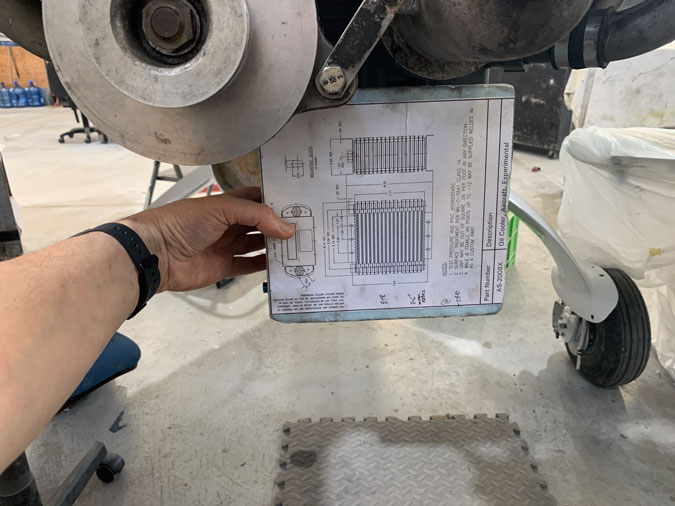
Perhaps 1/3 oil and 2/3 water will be more accurate. I am currently looking at an airplane oil cooler big enough to do a IO-540 but with more efficient entry and exit than a Cessna. I will be feeding in cool air, not hot and should have better ducting.
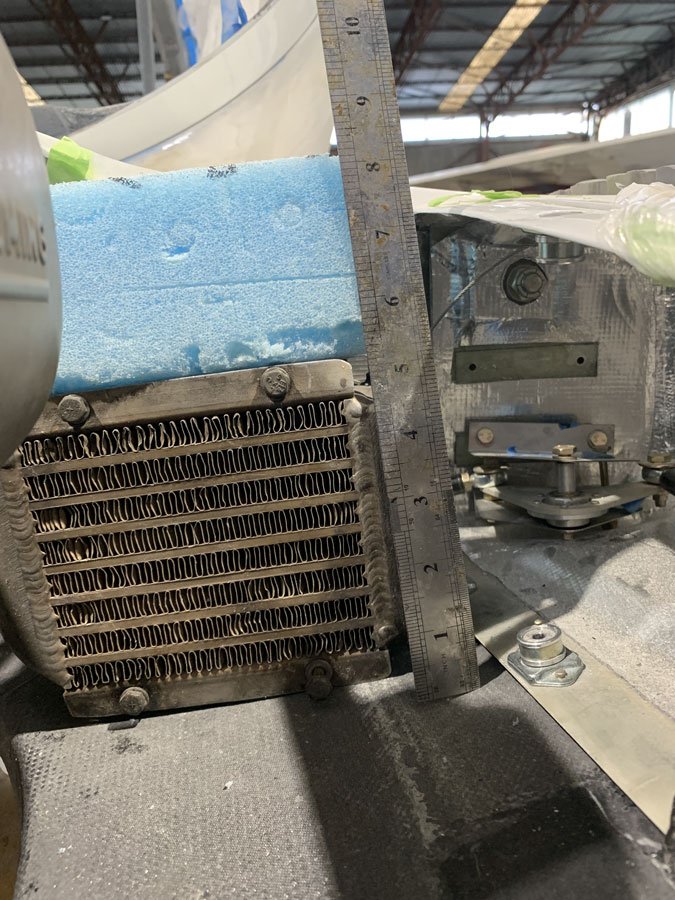
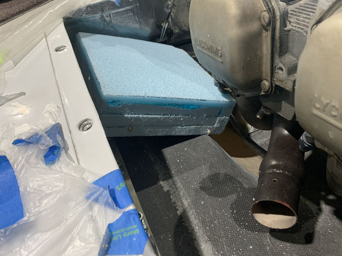
This is the size I’m thinking to use including the blue foam but it seems 8″ is all the space I have there and 7.5″ would be better. I’m currently talking to a oil cooler company. Or rather I send emails and they ignore them. Even in this position I will have to turn the air twice and alter the inlet scoop.
WATER COOLING
For the water cooling to get the square inches I need it might have to be three radiators with two extra inlets on the top of the cowl.
I have found a local guy who can make radiators to a specified size. The two big players Mezzo and PWR are not interested in helping.
These are the local guy’s thicknesses. I also need to add 10-20mm to the length for headers.
HOW BIG? – another take on the numbers
Rotax 912S 100HP Liquid Cooled (a well proven engine)
Oil Cooler 8.5″ X 5.25″ X 1.5″ (single row) 44.6sq”
Water Cooler 16″ X 5.75″ X 1.25″ (single row) 92.0sq”
50% water, 50% oil cooling (50HP each)
46sq” for 50HP (water) 22sq”(oil)
Voyager (Dick Rutan information) Continental IOL-200 rear (pusher)
55% water, 45% oil cooling (note front engine was air cooled)
Mazda 13B Rotary Engine 200HP (used in some aircraft)
Heat absorbed by water 130HP, Oil 50HP (of total 720HP for all heat)
72% water, 28% oil
In practice, 1/3 of cooling is oil with oil cooler volume about half of the water cooling
Grove AC-Aero Install 1000HP Sizes just guessed from the photo
Radiators 20″ X 10″ x 3″ (two core?) each
200 sq” each = 400sq” (one core so 800 sq”)
Oil Cooler size is unknown (not pictured). It is probably ‘small’ compared to the water radiators.
IF 3/4 of cooling is the water = 800 sq” for 750HP (1.06sq” for 1HP)
56sq” for 50HP
NOTE: this is about 20% over the Rotax size per 50HP
The Grove aircraft’s first iteration of the radiators as shown had more cooling than was needed.
AC-Aero 440X @300HP- My engine
with 2/3 water (200HP) would need 212sq”
If a two row (a bit over 2″ thick) 106sq” or 10″ X 11″ plus the oil cooler
Using BTU calculations as earlier in this post
For 300HP we need 384sq” of radiator (1″ thick)
If 1/3 is oil thats 256sq” for the water OR 128sq” for a two row.
42sq” for 50HP
Rough Conclusions
- Oil cooler will be Airflow Systems AS-2008X used for IO-540’s (240-300HP)
- Either 10″ x 11″ (106) or 10″ x 12″(128) Two row radiator for the water
- I will have to wait for the engine before seeing what I can fit. 10″X12″X 2″ doesn’t work the Long-EZ. I may have to do three small radiators plumbed together to get the required surface area.
Cooling efficiency relates directly to the installation which may allow both smaller radiators and less cooling drag. Most of the exact same information I have found scouring the net has been collected in Paul Lamar’s “How to Cool Your Wankel”.
Big takeaways are the Kays & London wedge for air entry and variations on the K&W trumpet diffusers for exit air.
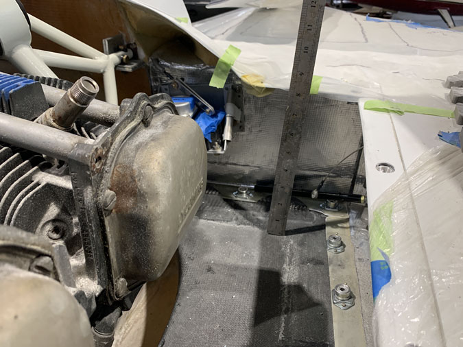
Planning Progress – Oil Cooler Position
A new spot has been ‘found’ for the oil cooler.
Its a big cooler so fitting it here is a real problem solver.
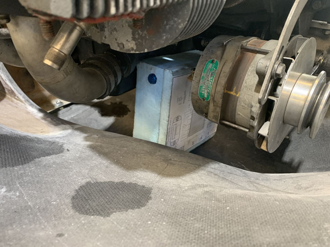
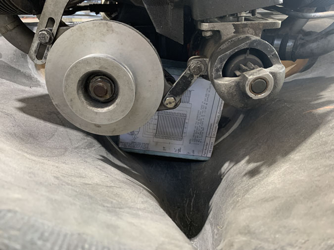
I’ve loaded up my dummy engine with a spare alternator and starter motor. This is a great spot between the alternator and the sump that will work a treat. I’ll use a KW trumpet duct to get the air onto the oil cooler face.
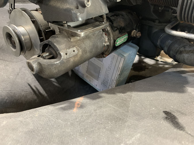
My B&C starter motor rather than the boat anchor Prestolite pictured is only 6.5″ back from the mounting area and leaves a perfect gap. I’ll also have mounting points off the sump or wherever I need to secure the cooler.
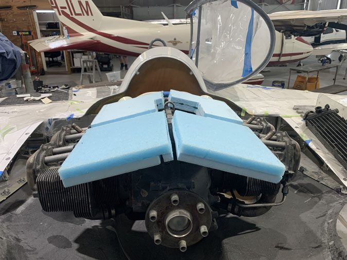
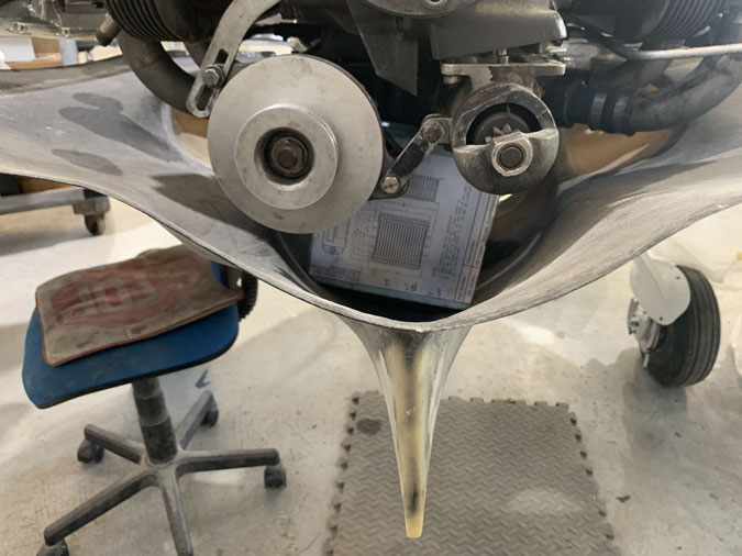
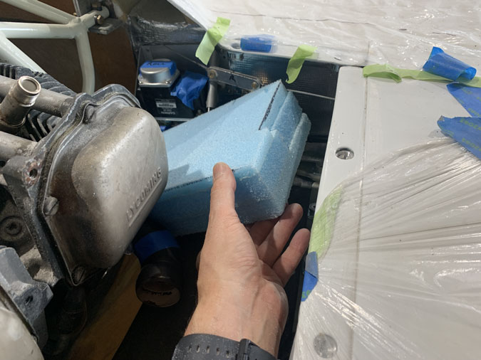
The cooler will sit a bit higher than my blue foam dummy. I shouldn’t have to alter the cowls at that point either. I could if I need them just a touch wider at the bottom. You can see a bit of a ‘Vee’ shape in front in the picture. This will squeeze the outgoing air into a funnel and should accelerate it.
Along with the previous picture you might see I can duct the outgoing air either to the top of the cowl opening OR I can make holes at the side of the boat tail for an exit. That might work very well. I’m thinking a shroud or top half of a duct on the engine side and using the cowl shape as the bottom. I would need to do a smart fitting so that when the cowl is placed on and fastened, it makes a true sealed duct.
Updated Water Cooling Radiator Plans
This cooler placement now frees up the armpit inlets for two water coolers at the sides and no extra inlets on the top of the cowl. This is a bit of a planning breakthrough. I will split off part of the right side armpit for air ducted to the cooler. The rest would go to a smaller water radiator on that side. A larger one on the left.
This is 10″ X 9″. I am now thinking I can go to the PWR 2.8″ high efficiency core. It is thick but I might be able to make it work. On the above picture, if I can get a core with a slanted bottom half say 6″ more this gives me 90+6×9/2 = 116square inches total. Given I want to be in the 120-130 range its looking good.
This all said I don’t think a cooler that big will fit in the left side. If I go to 8″ wide I’d have 80+24 = 104 square inches of top surface.
The right side is smaller again due to the offset cylinders and where the exhaust pipes start. If I’m 5″ wide here we get another 9X5 (45) so I’m up to 149 square inches. Again it may have to go smaller and this right side will have split air.
I’m still not 100% on how to turn the air to the radiators yet. I am 100% on modifying the cowl around the armpit intakes to give me more room inside for the radiators. That’s the next big task.