• Home
  • Flying
    • First Flight
  • Build by Chapter
    • Ch 3 Education
    • Ch 4 Fuselage Bulkheads
    • Ch 5 Fuselage Sides
    • Ch 6 Fuselage Assembly
    • Ch 7 Fuselage Exterior
    • Ch 8 Roll Over/Seat Belts
    • Ch 9 Main Gear/Landing Brake
    • Ch 10 Canard
    • Ch 11 Elevators
    • Ch 12 Canard Installation
    • Ch 13 Nose and Nose Gear
    • Ch 14 CenterSection Spar
    • Ch 15 Firewall and Accessories
    • Ch 16 Control System
    • Ch 17 Roll/Pitch Trim System
    • Ch 18 Canopy
    • Ch 19 Wings, Alierons
    • Ch 20 Winglets/Rudders
    • Ch 21 Strakes – Fuel/Baggage
    • Ch 22 Electrical System
    • Ch 23 Engine Installation
    • Ch 24 Covers/Consoles
    • Ch 25 Finishing
    • Ch 26 Upholstry
  • Build Mods
    • Liquid Cooling, Numbers, Weights and Flow
    • Cooling
      • Solving Ground Cooling 1
      • Solving Ground Cooling 2
      • Solving Ground Cooling 3
      • Solving Ground Cooling 4
      • Solving Ground Cooling 5
      • Solving Ground Cooling 6
      • Solving Ground Cooling7 – Test Data
      • Solving Ground Cooling 8 – Flap Building
      • Solving Ground Cooling 9 – Hinges
      • Solving Ground Cooling 10 – Lower Flaps
      • Solving Ground Cooling 11 – Upper Flaps
      • Solving Ground Cooling 12 – Completed
      • Cooling the Beast 1
      • Cooling the Beast 2 – Lower Cowl Expansion
      • Cooling the Beast 3 – KW Oil Cooler Diffuser
    • EVS (Enhanced Vision System)
    • Cowl Keeper
    • Rudder Gust Locks
    • Wing Fences
    • Post Cure
    • Hinge Upgrade
    • RAM Air & Hellhole Cover
    • Main Gear Beef Up
    • Pilot Side Windows
    • Baggage Pods
    • Winglet Intersection Fairings
    • Titanium Rollover
    • Nose Gear Doors
    • Wheel Pants/Gear Leg Fairing
    • Cabin heating System
    • Fuel System
    • Roll and Pitch Trim
    • Oxygen System
    • The Ferry Tank
    • Cruise Angle Indicator
    • Fire Extinguisher Install
  • Round the World
    • RTW Route East #12 rev1
    • Survival Equipment
    • Training Flights
  • Other Stuff
    • Blog
    • Around the World: RAAUS Sport Pilot Issue 110
    • Taxi Tests
    • Summary Feb ’24 from an SAAA Meeting
    • AOPA Pilot 27th Sept 2019
    • Build Tests
    • Flying Stories
      • A Long Easy Dream ’06
      • Townsville ’07
      • Cairns ’08
      • Albany ’08
      • East Coast ’08
      • Brisbane ’09
      • Cairns ’10
      • Perth ’10
    • Non Build Mods
      • F16 Scoop for JZE
      • Ram Air Box for JZE
      • Strange Tips
    • Milestones
    • Links
  • Contact

Build Tests

Home
Non Build Mods
Build Tests

Paint Adhesion Promoter

Date:  04-22-2022
Number of Hours:  1
Manual Reference:  no ref

This plane is getting a nose job, or to be more precise some very special artwork airbrushed onto the nose area.

The usual method when adding paint to an already painted surface is to sand or scotchbrite the area first. Adhesion promoter was suggested by the professional painter who did the primer and topcoat work on my plane. He uses a Boeing product for prep when art or sign work is added to a finished business jet.

Stacy Lourens, a Melbourne artist is going the airbrush work on my build and wanted to test products. I was reluctant to sand my freshly painted plane if an aerosol can would do the job instead.

Stacy can also be found on Facebook as well as the above Instagram link.

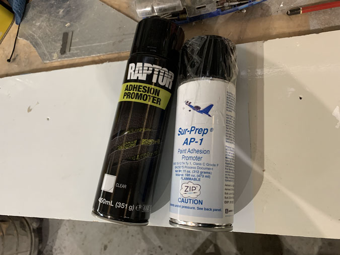
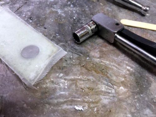
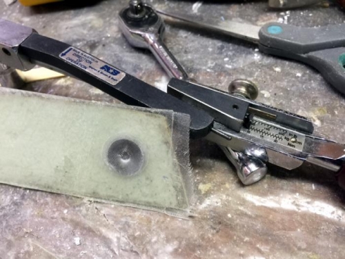
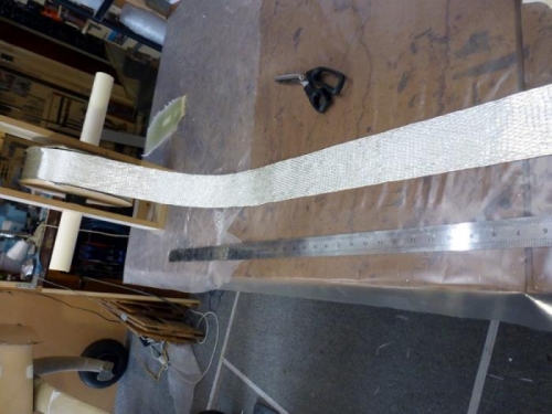
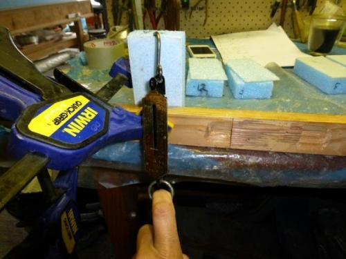
Here’s what we tried. The Raptor can is under $30 at a local automotive shop. The AP-1 is the Boeing product that costs way more than it should in Australia. The board they are sitting on is a test piece I used earlier when playing unsuccessfully with roll on paints.

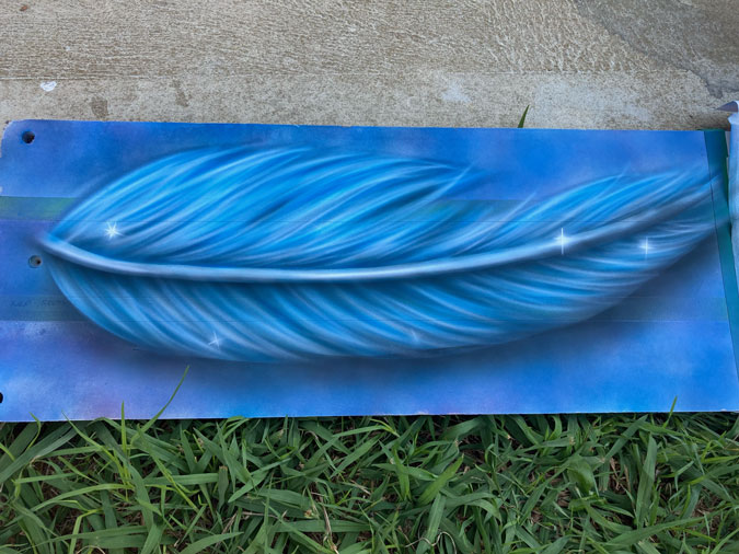
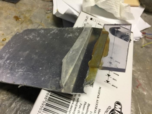
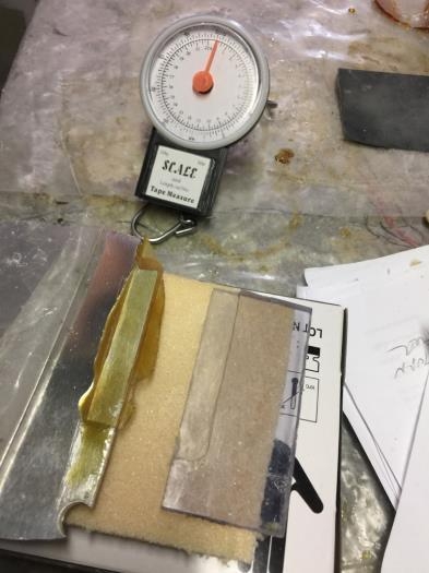
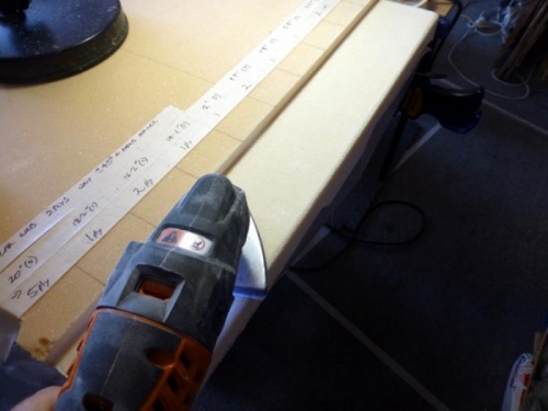
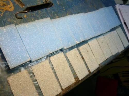
I divided the board long ways into three. The middle section was dulled with Maroon or Red Scotchbrite  This is in the 320-400 range although it depends too on how hard you press. The two outer sections were to be sprayed with one or other of the cans.

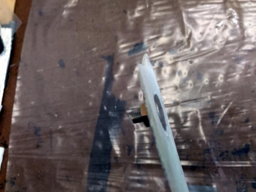
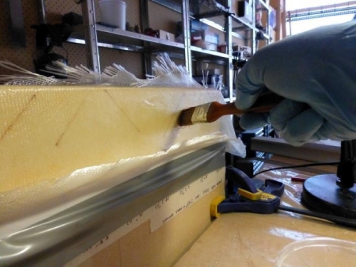
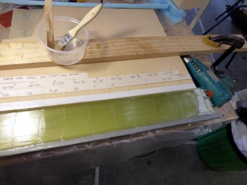
As you can see, Stacy has done a very beautiful feather. What happens next is a bit ugly…

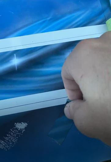
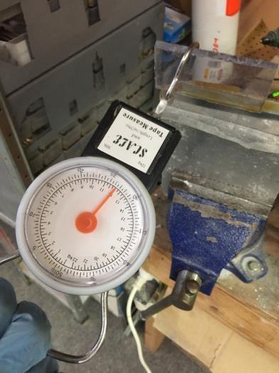
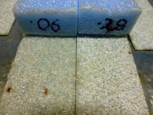
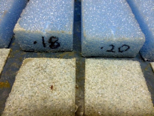
Yes clicking the picture will send you to the video of the test. The bottom line is that I’m going to have to sand or dull the nose for Stacy’s artwork. He uses a water-based paint and testing proves its going to really stick well in the sanded area.

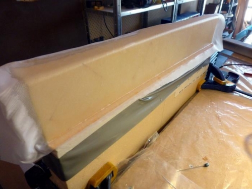
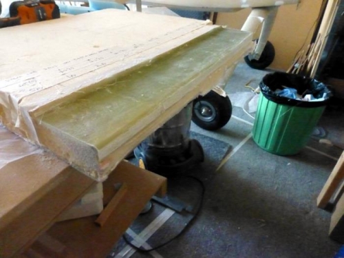
Just to add data to this test, an intercoat was used over the left vertical half of of the board about 15mts after the artwork. The intercoat had 30-40minutes to dry before the tape and scratch testing. The bottom line is that although this gave an improved result, the scotchbrite still wins for this nose section.

I am doing vinyl wrap items on the tails and for the registration marks (VH-XEZ). I will use one of the promoters for those. For the nose, its old school sanding as Stacy originally wanted. We did the science, a proper experiment, and I’m writing it here to make it real.


Flox PVC to Aluminium Test

Date:  05-22-2017
Number of Hours:  2
Manual Reference:  no ref

I needed to make a viewing port in my common sump by bonding 6mm PVC to 2024 T3 aluminium.

Does it stick? I make up a test piece as you see in pic 1. I am using EZ epoxy. The PVC is 6mm thick, I routed a 3mm step into it and primed with a commercial PVC primer which is really MEK and acetone combined. I roughened the aluminium surface with 40 grit sandpaper and cleaned with acetone.

I painted the surfaces with pure epoxy and then mixed up flox. I bonded the two surfaces, clamped them and left for two days to cure.

Pic 2 shows that I have put the joined pieces in a vice and hooked a weight measure device on the PVC and applied a shear force to try and break the bond at the weakest point.

At between 20 and 25lbs I was bending the .080″ 2024 and still the join held! I measured up to 26.5lbs which took a lot of fulling force. Somewhere between this and 30lbs the join failed.

That is seriously strong! Pic 3 shows that the join failed cleanly at the glue line. I also noted that a bit of glue that squeezed out onto un-sanded aluminium and unprimed PVC failed very cleanly suggesting how important prepping the surfaces is.

Test piece

Shear 26.6lbs OK

Failed

Pitot Testing 1

Date:  08-08-2016
Number of Hours:  3
Manual Reference:  no ref

I plan on a submerged pitot (anti-ice old glider style) that will sit just above my nose light. I have a nifty pressure tester that couples with an iphone app. The tester is the blue phone size rectangle in the pics and I used my ipad for the controls.

I really need to test as close to 180 knots as I can but maybe 40 or 50 will tell the story. I’m thinking can I angle the pitot without changing its pressure collection much at all?

Certainly a regular pitot would be an issue as such a small opening would soon have its lip covering the ‘relative wind’. What about a 1″ tube that collects the pressure before it gets to a submerged pitot getting the pressure off the back wall of the tube.

Interesting…. So I build a wind tunnel using my domestic fan in about an hour only to discover it makes around 6 knots of wind. Not enough!

Plan B is to stick my hand out of a moving car window for the test. Anybody need a used cardboard and pipe wind tunnel?

Wind tunnel

Tunnel exit

Testing pitot

ClickBond Test 1 Through a layup.

Date:  08-27-2015
Number of Hours:  2
Manual Reference:  no ref

I want to use Clickbonds in my build but I’ve never tested them myself. Will they turn when you torque up a nut? How strong are they? Are they going to be OK for primary controls?

Test 1 is going through a layup say instead of an AN screw for the rudders for example.
A separate test is needed for a bond to the outside of a surface.

For my test I used a clickbond that takes a standard AN3 nut.
I used a four ply layup of BID.
I after drilling a hole for the thread I routed a circle so the metal base wouldn’t stand proud of the outside. I probably lost most of one ply doing this.
I floxed the clickbond in place. I did not prepare the surface by cleaning it. I did not drill holes in the base to make fingers for the flox to grab. I wanted a worst case bond to test.
I covered the outside disk with the thinnest glass I have and peel plyed it.
The result was an almost smooth surface.

After cure, I used an AN3 lock nut and torqued to spec of 25 inch lbs (most references have AN3’s 20-25 inch pounds)
I kept upping the torque values. At 100 inch lbs the click bond distorted as you see in pic 3.
At 120 inch pounds the click bond failed by snapping at the base. I was using a wide area washer.
The glass did not fail and the click bond never rotated.

After this I have no hesitation in using these fasteners where applicable.

Dry fit

Cured in place

Test at 100 inch lbs

Spar Cap Tests 1

Date:  02-02-2014
Number of Hours:  10
Manual Reference:  no ref

The spar caps are a critical structural item on my plane build and I wanted to learn about how to do this work before attempting it on the real thing.

My goal was to build a section of the CS spar cap and find out how thick my special UNI tapes will layup per ply and to develop a good technique.

First step was to find a piece of scrap divinycell. Then I marked out a 3″ trough, actually 3.1″ to match my 80mm tapes. Just for the practice I put in a two ply UNI shearweb. I hard shelled it just to see how much extra time this added to the job and to try using power tools for sanding.

It adds quite a bit of time and while I think this method is good for some areas, in the end I used a wet micro layup for the real job later. I think the foam cells are so small here I’d go for the primary bond for the extra strength and skip all that sanding.

The open cell wing foam is another story.

Cutting a test cap trough

Laying up the test shear web

Peel ply the web


Spar Cap Tests 2

Date:  02-03-2014
Number of Hours:  6
Manual Reference:  no ref

Next step in my spar test is to layout the spar caps.

I first built a nifty UNI tape dispenser which will get a bit of use with CS spar, two wings and the canard to do.

It took 4 hours to layup only 20″ of this tape! The key thread of each piece needs to be teased out which then will release all the cross fibres which need careful pulling out. The tape then lies down beautifully.

It needs some attention to get the tapes in the correct direction so the threads are accessible for pulling out. I made a 3″ wide squeegee which was the heart of the technique for wetting out the cloth along with a heat gun.

My practice piece simulated the various thicknesses so that I could later workout how many plies I need to fill the CS spar troughs. This is important as we go from full length to shorter ones so it MUST have the right number to start with that go all the way.

UNI Tape dispenser

Cap weights

Results

Spar Cap Tests 3

Date:  02-04-2014
Number of Hours:  4
Manual Reference:  no ref

Once the piece was cured I removed the weights and peel ply and then cut all the foam off.
Here are some calcs and thicknesses close to what I will use for the top CS spar cap.

Ply   Depth Length BL
6      0.15    113
7      0.175  100
8      0.200   94
9      0.225   90
10    0.250   80
11    0.275   74
12    0.300   70
13    0.325   60
14    0.350   54
15    0.375   50
16    0.400   40
17    0.425   34
18    0.450   30
19    0.047   24

Test cap cured

Thicknesses marked out

Thin to thick

Peel Strength Tests 1

Date:  12-16-2013
Number of Hours:  10
Manual Reference:  no ref

This test was the second one seeking the best micro to epoxy mix when using the blue wing foam. I wanted to find out how much micro I could use in the mix, retain full maximum peel strength yet reduce weight. My second test was similar to the first but I was a lot more careful. I used 2 ply of the wing UNI glass.

All Blocks of foam were 8.2grams before layup 5” X 2.3”=11.5sq “ Blue Wing foam offcuts.
Peel force was measure by a cheap spring scale hooking under the foam and pulling consistently at an angle of about 150degrees down. Not deadly accurate but OK to give an indication. I tried to be as consistent as possible when pulling the cured glass from the foam.

I used the plans 1:1 by volume as my baseline in number1 sample. 1g of epoxy to 0.06 of micro is slightly wetter than plans but after testing is correct to use for divinycell foam. This blue wing foam is much weaker and has a very open cell structure so IMHO does not require so much epoxy in the mix and benefits greatly from having a thicker slurry. This fills the cells better and is easier to apply with less air being trapped on the surface.

You can see in the 3rd pic that all the samples came away cleanly from the foam proving its more a matter of weight and thickness, strength is not an issue. They were all sufficient. I’ll give a full report in the next entry.

10 samples

Force measurements

Samples peeled

Peel Strength Tests 2

Date:  12-22-2013
Number of Hours:  4
Manual Reference:  

Test 2 22/12/13 after 1 week cure

All Blocks 8.2grams before layup 5” X 2.3”=11.5sq “ Blue Wing foam off-cuts
Peel force was measure by a cheap spring scale hooking under the foam and pulling consistently at an angle of about 150degrees down

micro Weight Saving Peel Force Spread

1.1g 0.06 micro 17.6 zero(base) 6-7lbs very runny slurry

2. 1g 0.12 micro 17.6 zero 12

3. 1g 0.14 micro 16.9 – 0.7 12 nice easy spread

4. 1g 0.16 micro 16.5 -0.9 8

5. 1g 0.18 micro 16.6 -1.0 10 heavy spread, good fill

6. 1g 0.20 micro 16.7 -0.9 10 still just OK

7. 1g 0.22 micro 16.1 -1.5 10 very stiff

8. 1g 0.24 micro 17.1 -0.5 10

9. 1g 0.26 micro 17.2 -0.4 8-10 needs heat to mix

10. 1g 0.28 micro 17.0 -0.6 12 unusable, too stiff to mix


Conclusions
Around #5 seems a good mix with a 1 gram saving.
(#7 seems an anomaly in the weight numbers)
Peel strength is consistent with more epoxy (slurry) being weakest, testing was with an old spring scale and not accurate.

All mixes broke at the foam with more foam residue on #1 the rest were not dramatically less and were consistent. The very thick micro tends to ball up just a little under the glass which suggests it fills the holes more completely. Note that the very thick micro tends to be heavier as more is applied despite trying to keep the spread even..


Long-EZ Wing area is given as 81.99 sq feet (this is pretty close to plans for just the wing without strakes) call it 82sq’ (I got 82.1 doing a rough calc using plans page19-10)

Call this 164sq’ of blue foam upper and lower

Saving to be 1 gram per 11.5sq” or per 0.077sq foot
164 /0.077 = 2130grams = 4.7 pounds saving over the wings of a LE

This saving is compared to the plans ‘slurry’ mixture of about 1:1 by volume

Peel test in action

Thinnest and thickest similar

sample #5 0.18 looks good

CategoryLogsHours
All157617079
Uncategorized135
Ch 3 Education220
Ch 4 Fuselage Bulkheads25231
Ch 5 Fuselage Sides32283
Ch 6 Fuselage Assembly30270
Ch 7 Fuselage Exterior14140
Ch 8 Roll Over/Seat Belts990
Ch 9 Main Gear/Landing Brake71642
Ch 10 Canard28287
Ch 11 Elevators36298
Ch 12 Canard Installation12102
Ch 13 Nose and Nose Gear1291097
Ch 14 CenterSection Spar57525
Ch 15 Firewall and Accessories448
Ch 16 Control System27237
Ch 17 Roll/Pitch Trim System654
Ch 18 Canopy70502
Ch 19 Wings, Alierons1271090
Ch 20 Winglets/Rudders71528
Ch 21 Strakes - Fuel/Baggage65437
Ch 22 Electrical System591031
Ch 23 Engine Installation961152
Ch 24 Covers/Fairings/Consoles25202
Ch 25 Finishing561084
Ch 26 Upholstry340
Fuel System46310
Rollover1050
Cabin heating System60331
The Ferry Tank335
Blog2694182
Build Mods2252513
Nose Gear Doors856
Wheel Pants/Gear Leg Fairing40473
Oxygen System762
Roll and Pitch Trim964
Winglet Intersection Fairings445
Baggage Pods11104
Pilot Side Windows437
RAM Air & Hellhole Cover15177
Main Gear Beef Up322
Post Cure124
Fire Extinguisher16
Wing Fences13
EVS (Enhanced Visual System)130
Hinge Upgrade115
Cowl Keeper110
Rudder Gust Locks19
Cooling20607
Taxi Tests42
Flying10

Complete the Test Flight Program

2025/6/30 10:26:01

Round Australia in Four Flights

2026/4/1 10:26:01

Round the World Departure

2026/8/22 10:26:01

Rough River Flyin, Sept 23, 2026

2026/9/23 10:26:01

© Copyright 2025 Dave Berenholtz