• Home
  • Flying
    • First Flight
  • Build by Chapter
    • Ch 3 Education
    • Ch 4 Fuselage Bulkheads
    • Ch 5 Fuselage Sides
    • Ch 6 Fuselage Assembly
    • Ch 7 Fuselage Exterior
    • Ch 8 Roll Over/Seat Belts
    • Ch 9 Main Gear/Landing Brake
    • Ch 10 Canard
    • Ch 11 Elevators
    • Ch 12 Canard Installation
    • Ch 13 Nose and Nose Gear
    • Ch 14 CenterSection Spar
    • Ch 15 Firewall and Accessories
    • Ch 16 Control System
    • Ch 17 Roll/Pitch Trim System
    • Ch 18 Canopy
    • Ch 19 Wings, Alierons
    • Ch 20 Winglets/Rudders
    • Ch 21 Strakes – Fuel/Baggage
    • Ch 22 Electrical System
    • Ch 23 Engine Installation
    • Ch 24 Covers/Consoles
    • Ch 25 Finishing
    • Ch 26 Upholstry
  • Build Mods
    • Liquid Cooling, Numbers, Weights and Flow
    • Cooling
      • Solving Ground Cooling 1
      • Solving Ground Cooling 2
      • Solving Ground Cooling 3
      • Solving Ground Cooling 4
      • Solving Ground Cooling 5
      • Solving Ground Cooling 6
      • Solving Ground Cooling7 – Test Data
      • Solving Ground Cooling 8 – Flap Building
      • Solving Ground Cooling 9 – Hinges
      • Solving Ground Cooling 10 – Lower Flaps
      • Solving Ground Cooling 11 – Upper Flaps
      • Solving Ground Cooling 12 – Completed
      • Cooling the Beast 1
      • Cooling the Beast 2 – Lower Cowl Expansion
      • Cooling the Beast 3 – KW Oil Cooler Diffuser
    • EVS (Enhanced Vision System)
    • Cowl Keeper
    • Rudder Gust Locks
    • Wing Fences
    • Post Cure
    • Hinge Upgrade
    • RAM Air & Hellhole Cover
    • Main Gear Beef Up
    • Pilot Side Windows
    • Baggage Pods
    • Winglet Intersection Fairings
    • Titanium Rollover
    • Nose Gear Doors
    • Wheel Pants/Gear Leg Fairing
    • Cabin heating System
    • Fuel System
    • Roll and Pitch Trim
    • Oxygen System
    • The Ferry Tank
    • Cruise Angle Indicator
    • Fire Extinguisher Install
  • Round the World
    • RTW Route East #12 rev1
    • Survival Equipment
    • Training Flights
  • Other Stuff
    • Blog
    • Around the World: RAAUS Sport Pilot Issue 110
    • Taxi Tests
    • Summary Feb ’24 from an SAAA Meeting
    • AOPA Pilot 27th Sept 2019
    • Build Tests
    • Flying Stories
      • A Long Easy Dream ’06
      • Townsville ’07
      • Cairns ’08
      • Albany ’08
      • East Coast ’08
      • Brisbane ’09
      • Cairns ’10
      • Perth ’10
    • Non Build Mods
      • F16 Scoop for JZE
      • Ram Air Box for JZE
      • Strange Tips
    • Milestones
    • Links
  • Contact

Roll and Pitch Trim

Home
Build Mods
Roll and Pitch Trim

Roll and Pitch Trim Update

Date:  09-16-2022
Number of Hours:  15
Manual Reference:  no ref

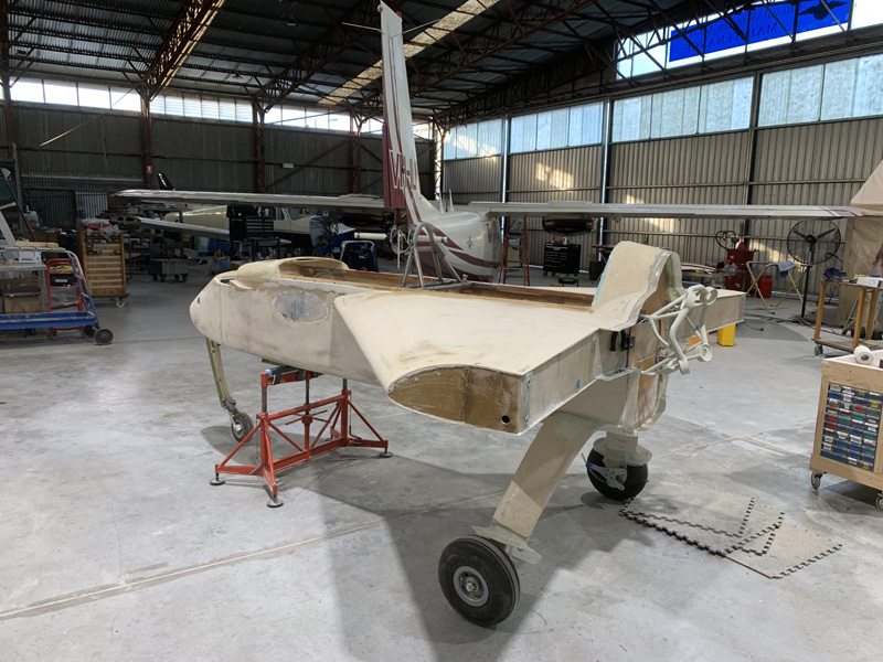
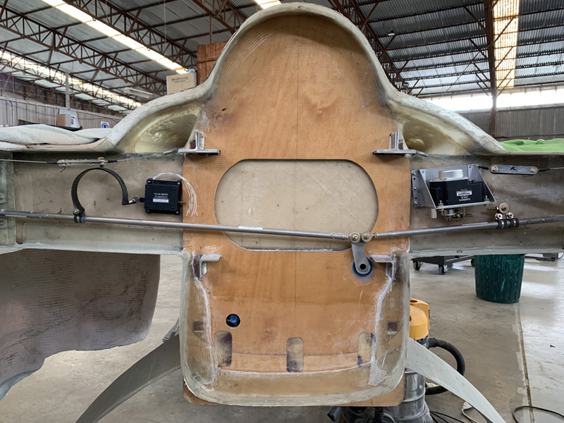
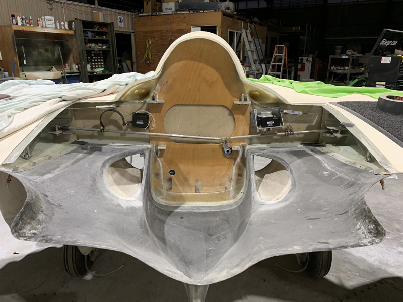
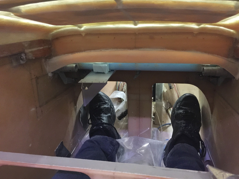
Its September 2022 and I’m still waiting on the engine. It is time to do some ‘final’ set up work on various systems. Here I spent hours on the canard and put the servos back in. Both Garmin servos have been replaced as they were faulty from day one. We didn’t find out until we hooked it all up to the installed avionics. The warranty goes from the purchase date, not the installed date on ‘experimentals’. Certified purchases get warranty on THE SAME item from the installed date. Hmmm.

I ended up paying a relatively minor amount after much ‘discussion’. Now Garmin will replace any servos as so many have been showing up faulty. They will be fixing their production issues I’m told.

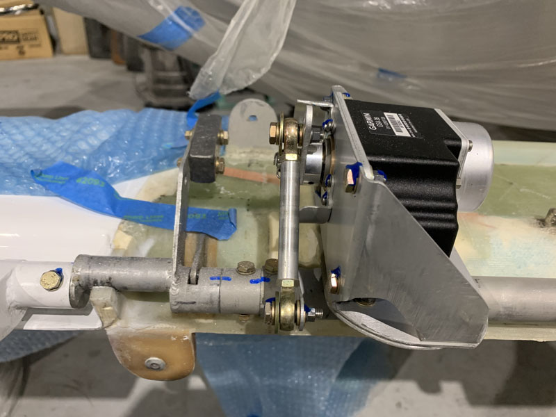
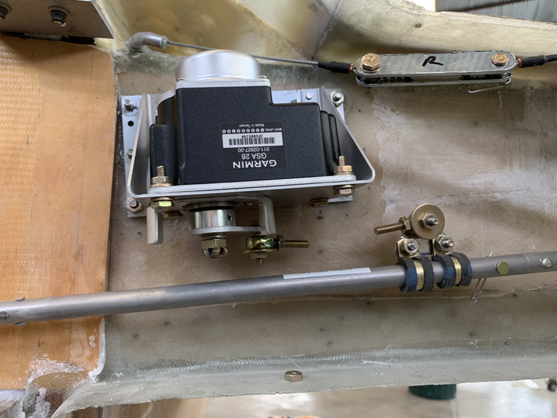
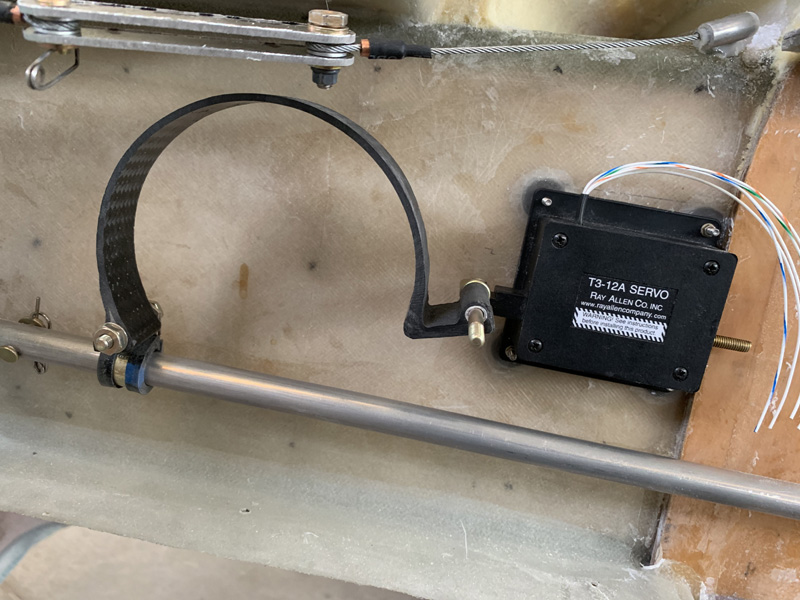
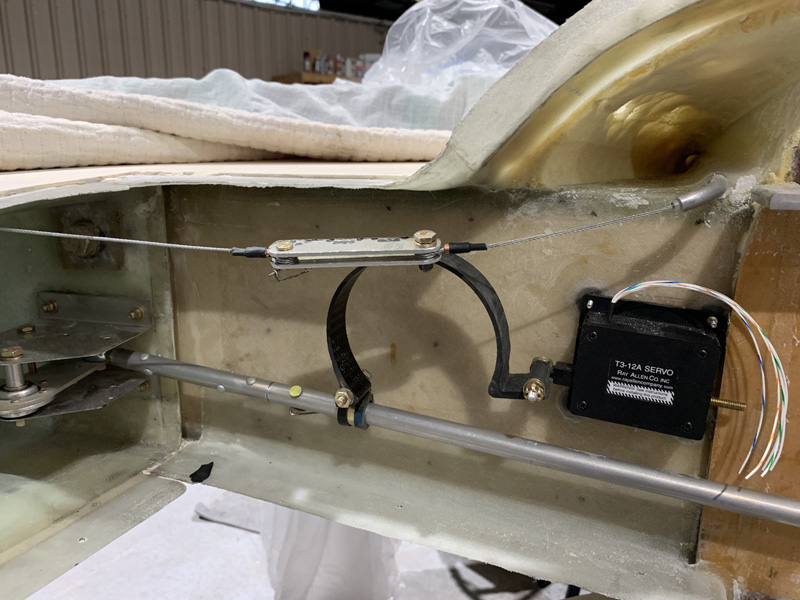
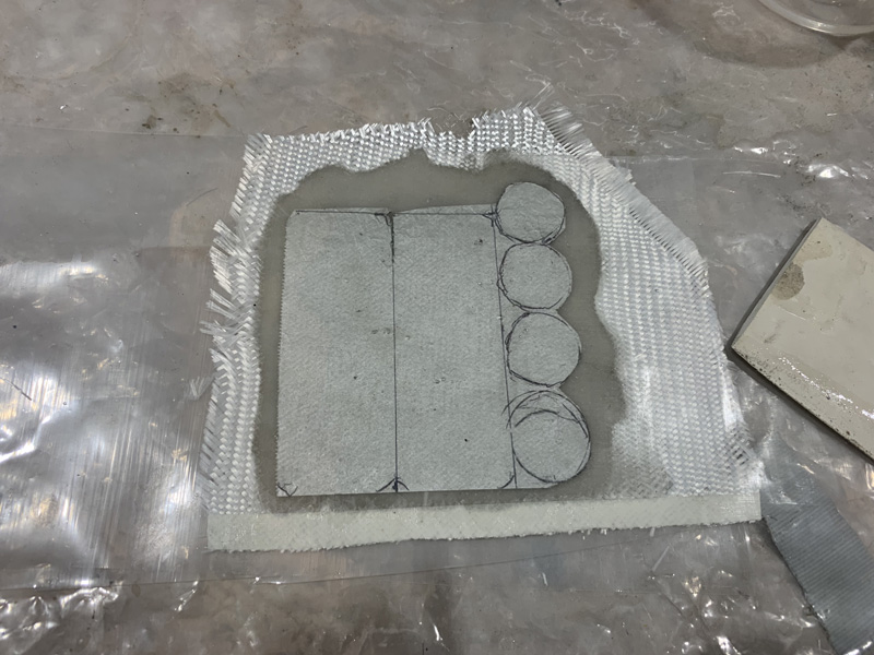
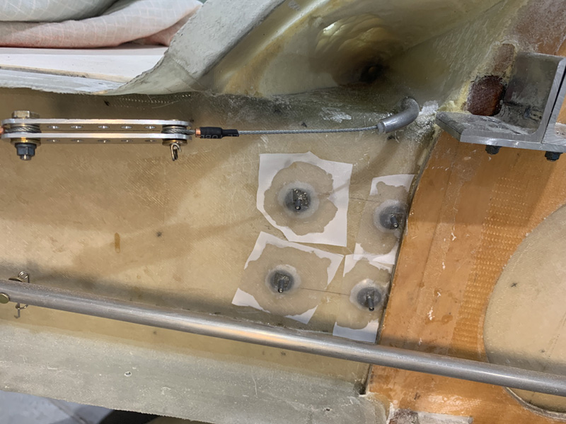
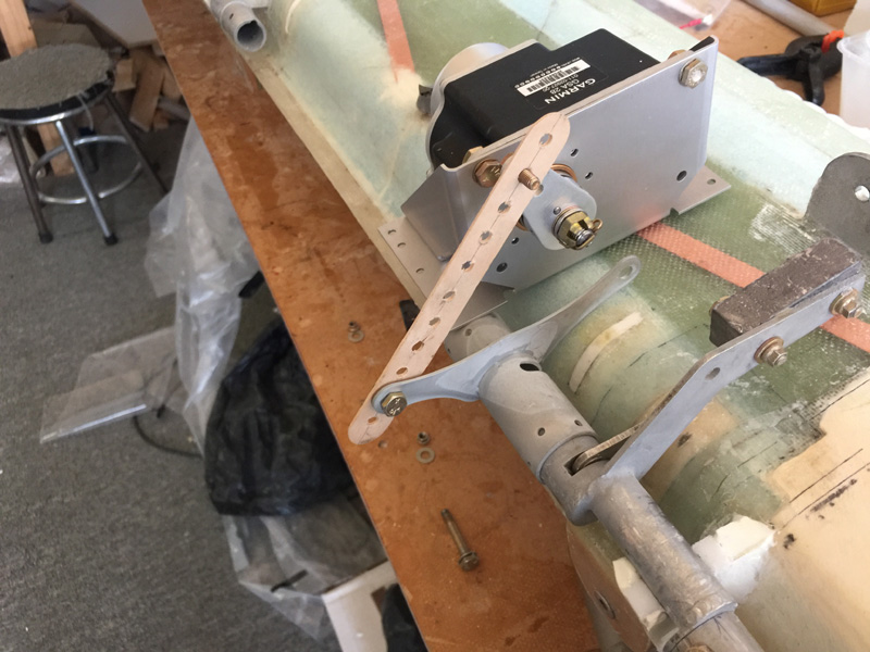
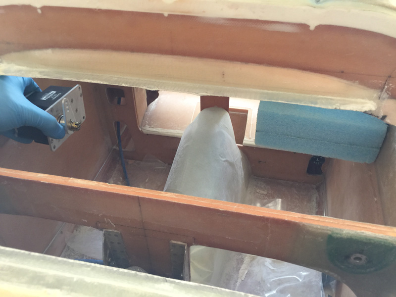
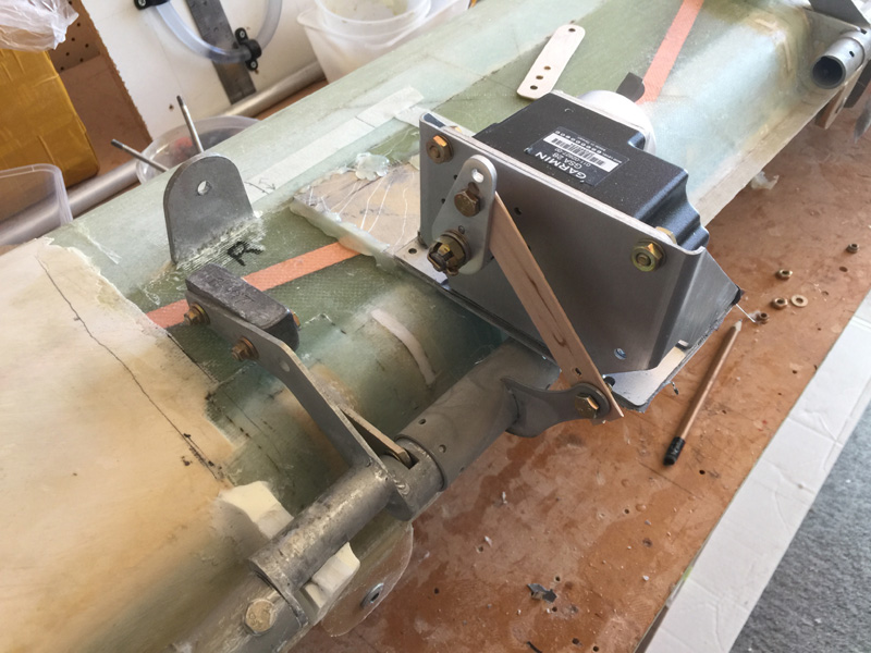
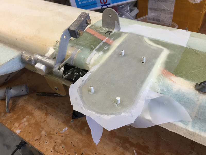
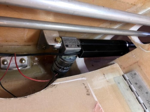
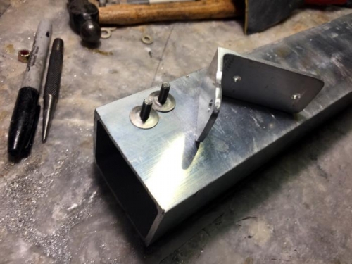
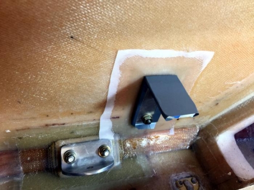
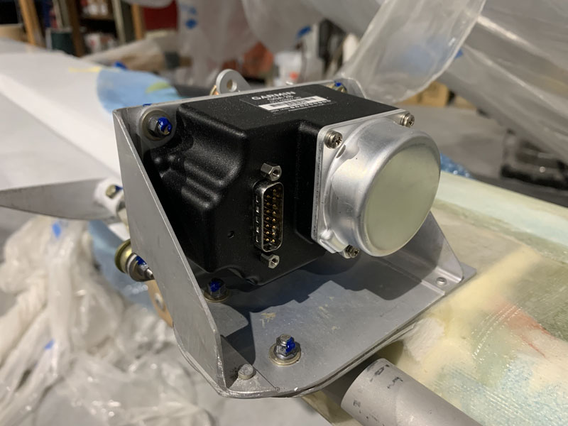
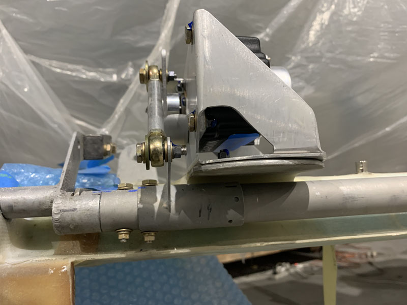
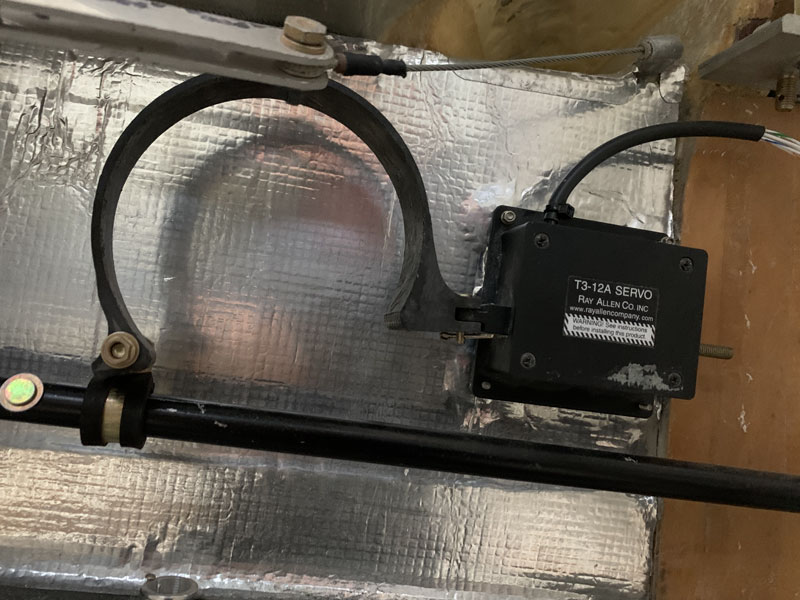
The pitch servo now in place. The blue torque seal is a ‘code’ to say ‘I have done this bolt and nut up to spec’. The idea is that when i am ready for inspection I’ll know what needs to be tightened or checked and what has already been done.

The blue lines on the tubes are in case I have to disassemble them so I can get things back to the same place without a lot of refitting. This setup with the arm ensure it can not lock over center. Its on the inner bolt hole of the arm according to other canard flyers who say this is the best place.

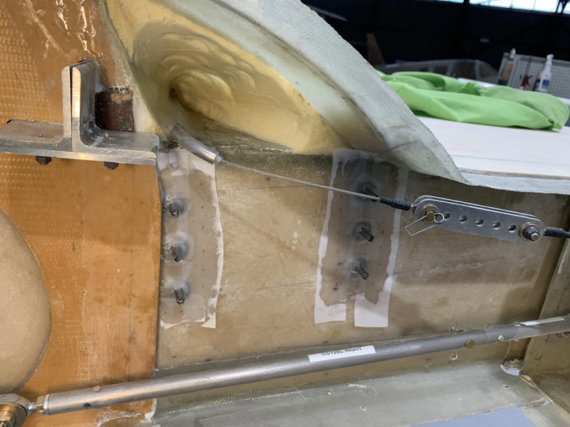
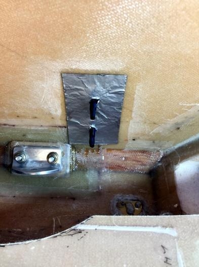
I had to tweak the hard stops for the servo which guard against runaway. There is a very wide throw in both directions on this elevator system. In flight with JZE I use very little of it.

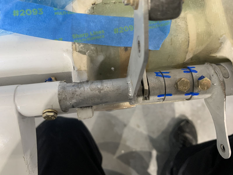
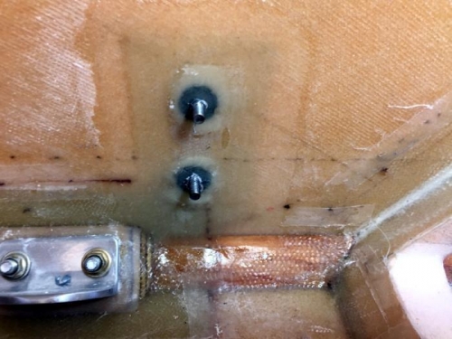
I had these apart a while ago and it was very easy to put bolts in different holes. The problem is everything nearly works…but not quite. The blue paint lines should help if they have to come apart in the future.

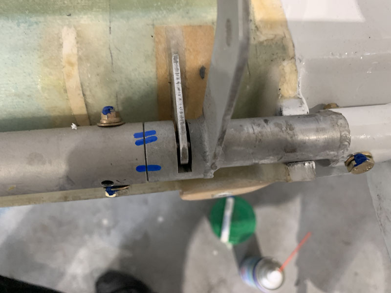
There is some friction in this elevator system that I am not happy about. It might make no difference.. or maybe it will. The fix is to reduce the excellent fit of the phenolic runners. That’s where its grabbing slightly. To do that I need to get the hinge pins out…again.  Its a horrible frustrating and difficult job. Did I mention, horrible.

Ok I am thinking about doing the fix… or maybe see if it is in fact a problem during test flying. It will either feel a little stiff or not be noticeable at all. It will not be a safety of flight thing. it MIGHT be an issue near the onset of flutter. I don’t know… so I’m seeking advice.

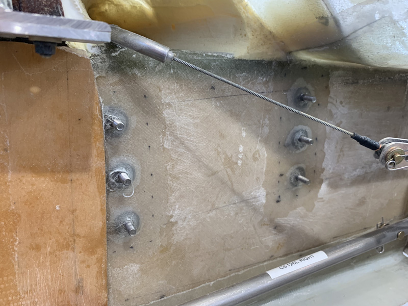
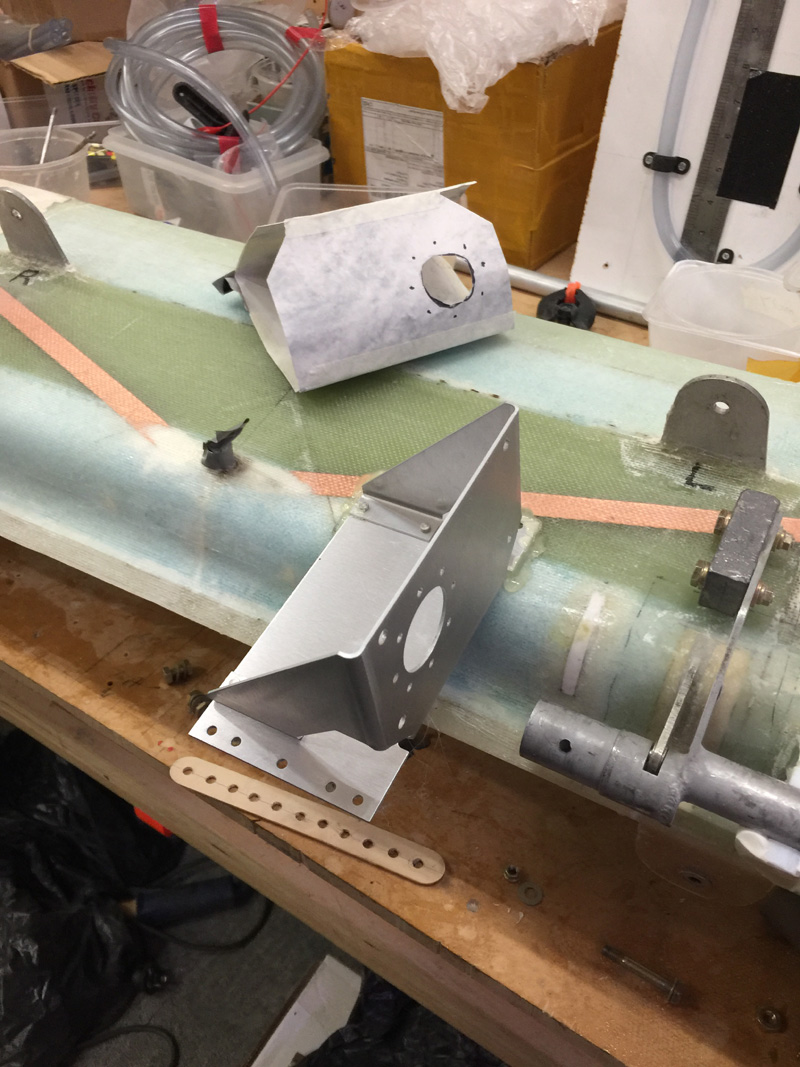
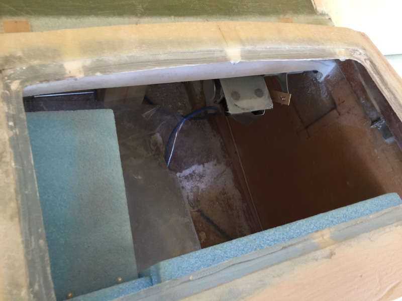
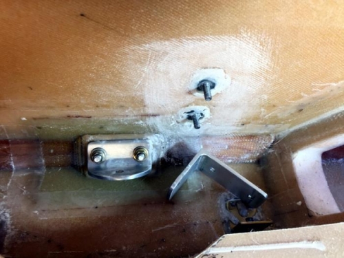
Good access for the nuts here.

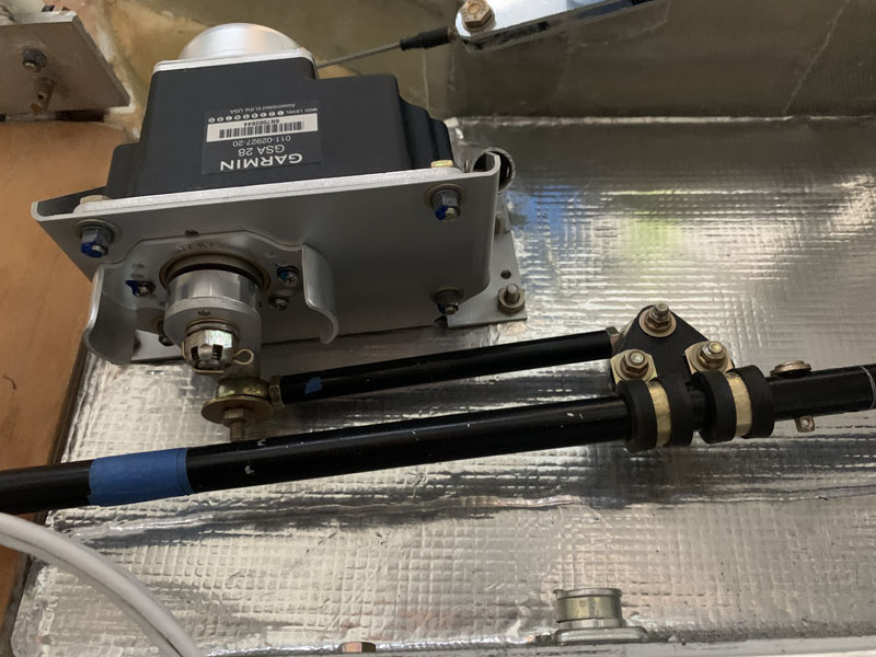
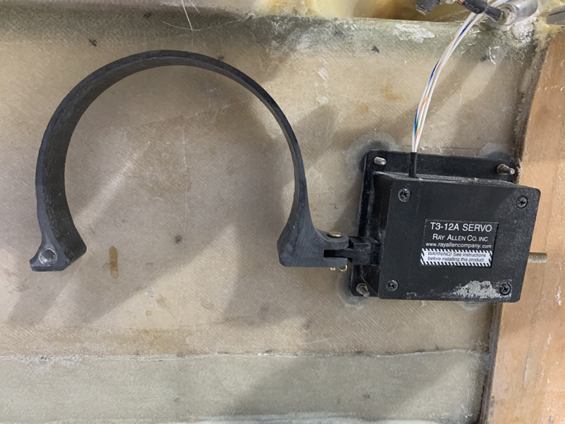
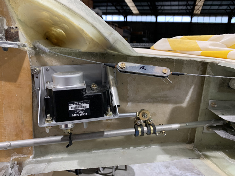
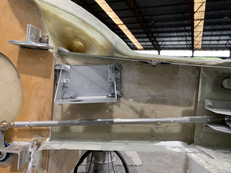
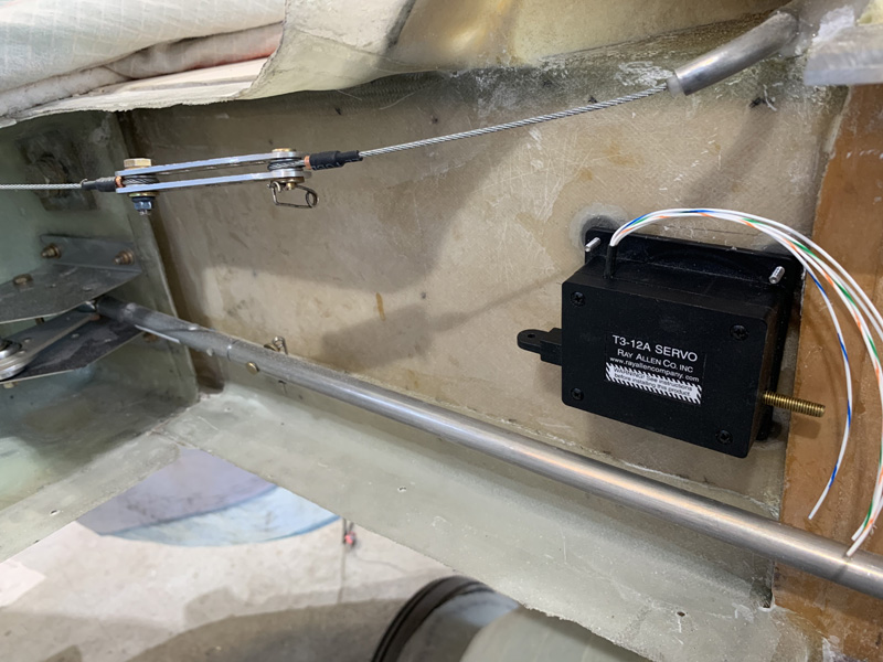
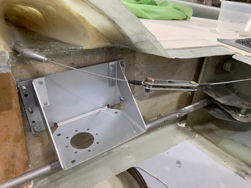
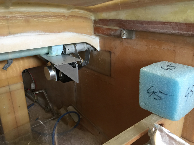
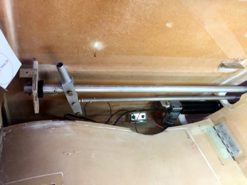
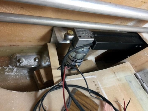
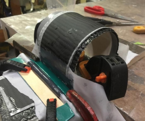
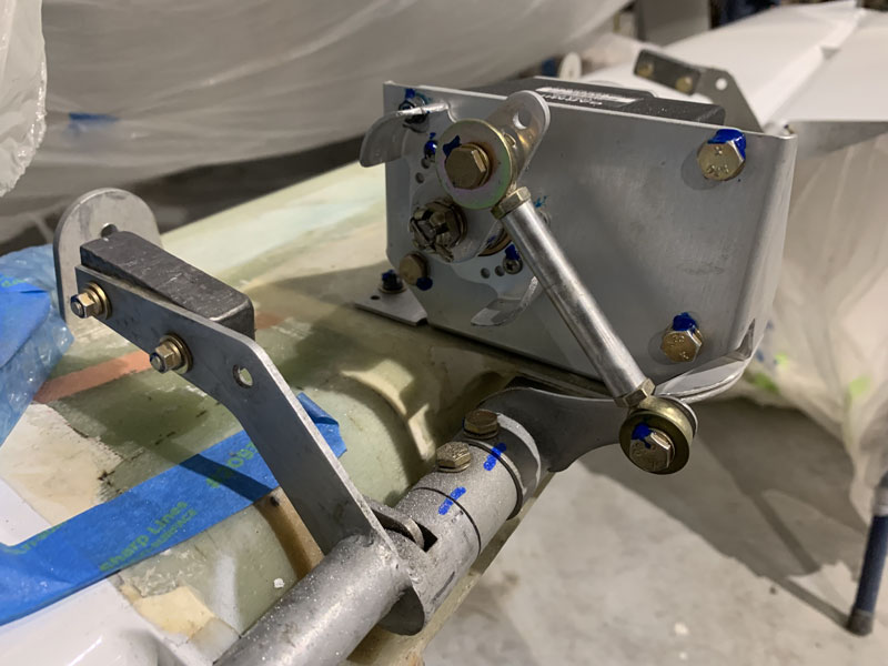
This is the roll servo

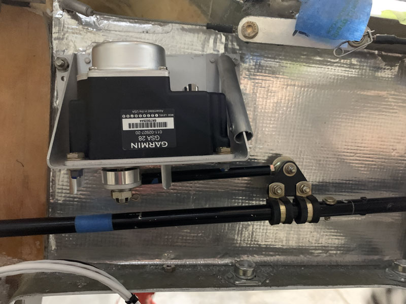
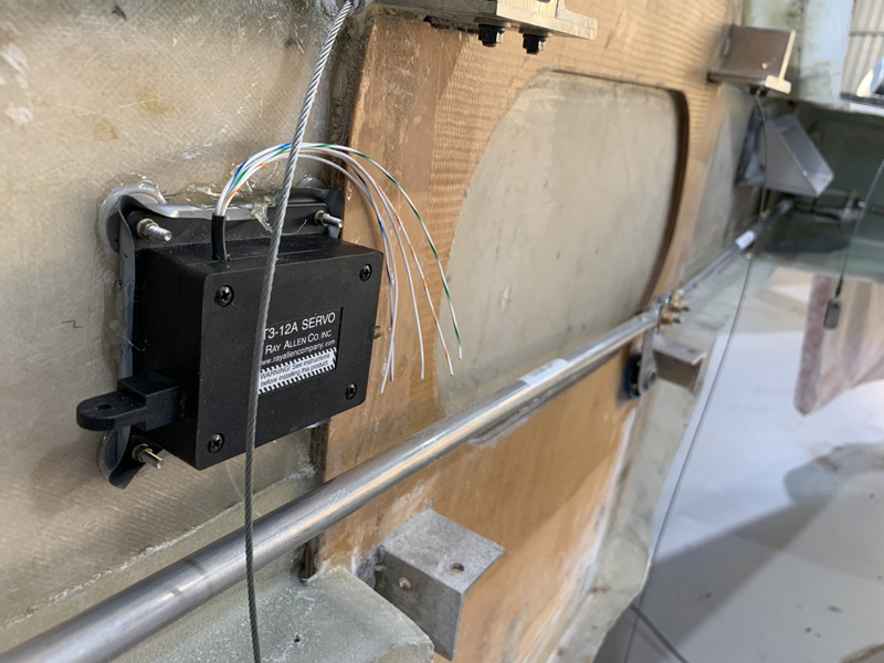
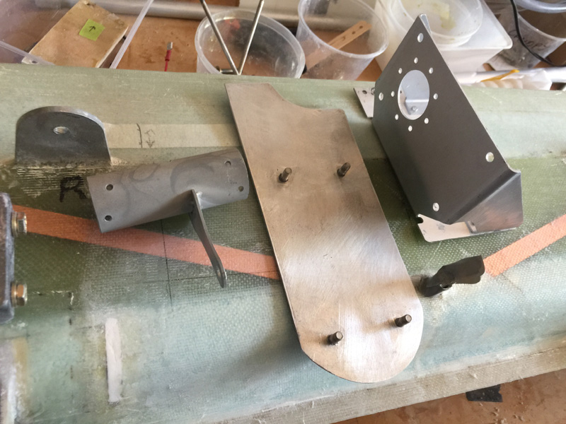
Roll servo again, note the guard I have in case the rudder pedal cable gets too close. I don’t want a sharp edge wearing away the cable over time.

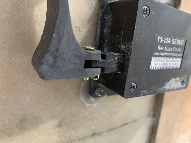
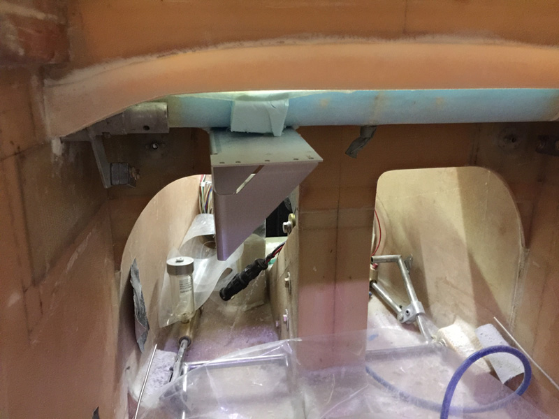
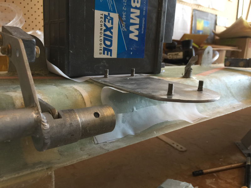
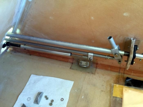
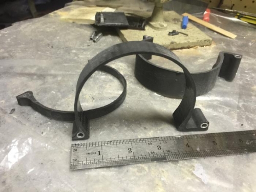
This is the roll TRIM servo and spring. Not yet tightened up but ready to go.


Roll Trim Servo Update

Date:  07-08-2019
Number of Hours:  3
Manual Reference:  no ref

Just an update to the roll trim connection to the Ray Allen servo.

The issue has been the connection to the CF spring. Here you can see my latest solution which I am very happy with.

Sure, its a minor thing. Normally the spring connection is rotated to match the other end, which I did originally. This works if your servo is also at 90 degrees to the spar. That seems misguided to me, why take up more room next to the firewall where access is always an issue?

The solution was to thicken the right hand side end of the spring with many extra layers of Carbon fiber (CF). Then I carefully cut a slot to receive the servo tab.  Next was a slightly longer clevis pin and I now have a system that makes sense to me.

You can just see the spring in this recent shot of the build.


Roll Trim and Aileron Servo Mount 2

Date:  04-28-2019
Number of Hours:  8
Manual Reference:  no ref

I wanted to complete roll trims and aileron servo mount so I could put the engine mount back and keep moving.

The aileron autopilot servo filled well in its new position. I am happy with the double P-clamp idea and made a very simple triangle in aluminium with three holes to mount these and the end rod.

For attaching the spring to the little servo an AN42B-12 (drilled) worked out well. I did have to get the AN3 size hole filled in with weld and re-drill it for a small clevis pin.

Here are the two roll/aileron fittings in place.

I like this shot with the lower cowl on. Looks ‘interesting’.

I had the small aluminium servo push rod center drilled for me on a lathe. I finished off with the 3/16″ tap. You might notice on the right of the servo holder is a piece of aluminium tubing. I was concerned that it was possible for the rudder cable disconnect piece to snag on the holder. The tubing allows any contact to just roll off. I cut a slit in the tube and secured it with one rivet. Simple.

The servo with its special pin in place. I’ll use a castle nut and split pin for the final set up. Lets call these good for now.

Roll Trim and Aileron Servo Mount 1

Date:  04-23-2019
Number of Hours:  8
Manual Reference:  16-2

The roll trim Ray Allen servo is going on the spar and the other side has the aileron autopilot servo.

This is my second attempt at setting up the clickbonds for the roll/aileron server. I first did them on this  side nearer the right wing root. Then I saw the potential to interfere with the rudder cable quick disconnect. So I knocked off the click bonds, cleaned it all up and went again as you see above.

In this new position I should be well clear of the cable …or so I thought until I later changed the cable connector. <sigh>

The roll trim seemed quite happy on the other side. You can see the initial servo position in the right side of the pic.

Once the clickbonds were floxed on I made the usual two ply BID patches.

These roll trim bonds are the smallest I have. The load is not significant to hold a lightweight Ray Allen servo.

The autopilot servo I’ve gone for 6 heavier clickbonds. This needs to be rock solid.

Looking OK so far this side.

I suspect on this right side my new connector may touch the servo at times. I may make a servo cover later on.


Pitch Trim Servo Install 1

Date:  09-08-2018
Number of Hours:  10
Manual Reference:  no ref

As VH-XEZ will be a well equipped IFR aircraft, I’ll be having an auto pilot. I’m using mainly Garmin instruments and this means a GSA 28 (Autopilot Servo) for pitch and another will be installed later for roll. I’ve been in touch with the very helpful guys at Garmin, some of whom have Long-EZ. They tell me the place to install these servos is on the canard.

I read the install manual a few times and got familiar with things. I’ve already bought the servos and a bracket kit. It looked like it goes somewhere in the above area. I made a cardboard cutout after a while as I just couldn’t see how to get the the canard on and off once I install the servo! It was snagging on all the nice air sealing work I’d done. The offset torque tube I’m using also made things harder because the counterweight also seems to snag.

As I’m saying more and more, “No modification goes un-punished”.

I had purchase the trim bracket with this servo in mind. I guess this was a rare planning win. You can see above a beginning of how it might fit and operate. I’m just using a drilled mixing stick to get a feel for placement and the ‘throw’ of the servo and elevator together.

I have concerns about how far from the canard edge this thing needs to go so I can still get the canard off. With hot gluing things in place I tried several positions.

This spot seemed pretty good. My feet work out OK.

Here’s the reverse angle. That blue block is the radio stuff going full length forward to F28 (I think it is). Fellow LE builder and ace planner, Wade Parton, commented that I might run into trouble with my Garmin main stack of toys on that side being too deep. He was right, thanks Wade! Maybe I would have spotted it in time or maybe I’d be in a world of hurt in a few months doing the avionics install. Now we will never know.

Here’s a mock up on the opposite side All I have in from here is the G5 which is not very deep. There is still plenty of room for the pitch arm from the stick that goes on that right side. This is another mock up with more hot glue.

Each time I have to lift the canard off and manipulate it in my small room. Its been a couple of dozen so far. I may need a physio, things are starting to hurt.

Now I’m happy with placement I hunted everywhere for a bit of aluminium for the base. I’ve added click bonds and then glassed over the back with a ply of BID.

More mock up tests. You can see I’ve modified the pitch trim arm too. The canard again went on and off several times.

Here it is in place as I’ve been trimming my air tight fairings around the canard a little too. The foam block on the left is where the GTN750 goes so being on the opposite side is lots of room. The downside is that the overhang of the servo relative to the canard is quite extreme. I’m going to have to make the attachment very solid.

Here’s my base place with the clickbonds ready for fitting after prep work.. The canard is removable, but its a little tricky. I may do a write up in the flight manual on the ‘how’.

I’m using West with flox here and a bit of weight while it cures. That metal MUST clear the torque tube of course. I like West and metal as its just a little less brittle than my usual epoxy. Good for this type of job, and it has a fast hardener.

After the Canard to metal cured, I’ve done two ply of BID overlapping onto the canard and one of UND on top. I’ve also added some micro underneath. I’m going to make a support there and shape it so its clear of the torque tube but still adds a little extra strength to that ‘overhang’ with the servo on it.

Pitch Trim in Place

Date:  05-02-2017
Number of Hours:  1
Manual Reference:  no ref

Here’s the pitch trim now installed. ‘Marco’ made the push rod section for me, a beautiful job, and just as a friend as he is not doing this commercially (sorry).

You can see I have the piston section pretty close to parallel to the control stick, just a bit of an angle for safe clearance. This setup should give me a nice linear trim.

The seat belt attachment at the back in pic 3 is for my aux fuel tank hold downs. It will be isolated in use so it can not interfere with this primary control. I am very mindful of this and will probably make a cover so I know it is safe.

I do have mild concerns about some noise from the actuator getting into my system however good earths going to the correct places should make it quiet. I’ll probably have the large power cables that side and audio and signal lines on the left side of the plane.

The actuator is from Motion Systems Corporation #85615-RH-30-3B-0.250-DC1-WP-POT, the ‘POT’ is for a built in potentiometer so I can have a position readout on my main screen. It was not cheap… and is a top quality actuator appropriate for my elevator trim system.

Good clearances

Side view

At the back

Pitch Trim Click Bond Mount 1

Date:  04-30-2017
Number of Hours:  6
Manual Reference:  no ref

The next two logs are really to document my installation of two clickbonds to mount the pitch trim bracket.

I made the bracket from a rectangular piece of 6061-T6 that was once a gyrocopter tail boom. That’s another story. I cut it out with a jig saw and then trimmed to make an L shape as you see in pic 1 sitting next to the click bonds.

Why did it take 6 hours? … because I made a complete bracket all the way down to a sandpaper finish, but the main 1/4″ hole was not sitting where it should. So I had to remake it from scratch.

Once the bracket was good I placed release tape on the rear and prepped the fuselage side and acetone cleaned the click bonds which were then secured via nuts to the bracket for an exact placement. I used West epoxy for the flox which is nice and thick for metal to glass bonds and pure epoxy on the wall. I then assembled the pitch trim in place and used a few sticks as in pic 2 to hold it in the exact position I wanted for the cure.

Pic 3 shows I managed not to stick the bracket on although it took a bit to release it. You can see I have prepped the fuselage wall again, dulling the fresh epoxy as well.

Bracket and source metal

Positioned in place

After the cure

Pitch Trim Click Bond Mount 2

Date:  04-04-2017
Number of Hours:  3
Manual Reference:  no ref

Next up was three plies of glass laid up individually on foil. I also very carefully moved the fibers where the holes for the threads went rather than just poke a hole. I protected the threads with some heat shrink while I put the glass on. Before that of course I wetted the area out with pure epoxy and then added a little flox to ease the transition from the clickbond to the base glass of the fuselage side. Its not much flox, but I feel this would minimise or eliminate any air getting trapped.

I was very careful with each separate ply and then a covering of peel ply with pre made holes went on top. The BID glass was biased at 45 degrees and I ensured no air bubbles and used my gloved fingers for all the smoothing down.

At the end I removed the heat shrink and put the bracket back using fresh grey duct tape for a release. The nuts were lightly done up so that the wet glass would be an extra good fit for the bracket. Pic 2 and its ready to cure.

Pic 3 and I have removed the bracket and with the peel ply off, I have a pretty clean install. It is amazingly strong as it should be for such an important part as the aircraft elevator trim.

Foil technique

3 ply with peel ply

Super strong click bonds

Wright-Hanka Roll Trim Spring 1

Date:  05-03-2016
Number of Hours:  10
Manual Reference:  no ref

While doing other jobs I thought I’d build the spring for the roll trim. I’m using the Wright-Hanka system that a few other canards have done with success. Mine will be an electric trim operated from a hat switch on the control stick. There will be a servo pulling and pushing the roll pushrod with one of these horse-shoe shaped springs in between.

I thought I’d try it in carbon fiber as I had a small amount of cloth. First up I found a bit of pipe and hot glued it to a board after taking out a bit on the bottom leaving a curve around 270 degrees. Then I covered everything in duct tape and added some clear tape around the base as you see in pic 1.

I did a six ply layup initially and peel plied it. Then I added some aluminium tube that I had drilled out to accept an AN3 size bolt. I did another 5 plys on one side about an inch long with a bit of flox for a transition. Once cured I did the other side using a mixing stick spacer and a couple of clamps and more peel ply. All this done as shown on Pic 2.

Pic 3 has my springs which look even nicer in person! I only needed one at 5/8″ diameter. I’ve cut one down to .8″ and have a thicker and thinner as spares. I made the initial mold wide enough to do a few as it was really the same amount of work as one. It feels great and nice and springy. I’m pleased with this, the carbon is very pretty.

Duct taped model

Laid up and tubes in place

A beautiful spring with spares

CategoryLogsHours
All157617079
Uncategorized135
Ch 3 Education220
Ch 4 Fuselage Bulkheads25231
Ch 5 Fuselage Sides32283
Ch 6 Fuselage Assembly30270
Ch 7 Fuselage Exterior14140
Ch 8 Roll Over/Seat Belts990
Ch 9 Main Gear/Landing Brake71642
Ch 10 Canard28287
Ch 11 Elevators36298
Ch 12 Canard Installation12102
Ch 13 Nose and Nose Gear1291097
Ch 14 CenterSection Spar57525
Ch 15 Firewall and Accessories448
Ch 16 Control System27237
Ch 17 Roll/Pitch Trim System654
Ch 18 Canopy70502
Ch 19 Wings, Alierons1271090
Ch 20 Winglets/Rudders71528
Ch 21 Strakes - Fuel/Baggage65437
Ch 22 Electrical System591031
Ch 23 Engine Installation961152
Ch 24 Covers/Fairings/Consoles25202
Ch 25 Finishing561084
Ch 26 Upholstry340
Fuel System46310
Rollover1050
Cabin heating System60331
The Ferry Tank335
Blog2694182
Build Mods2252513
Nose Gear Doors856
Wheel Pants/Gear Leg Fairing40473
Oxygen System762
Roll and Pitch Trim964
Winglet Intersection Fairings445
Baggage Pods11104
Pilot Side Windows437
RAM Air & Hellhole Cover15177
Main Gear Beef Up322
Post Cure124
Fire Extinguisher16
Wing Fences13
EVS (Enhanced Visual System)130
Hinge Upgrade115
Cowl Keeper110
Rudder Gust Locks19
Cooling20607
Taxi Tests42
Flying10

Complete the Test Flight Program

2025/6/30 10:26:01

Round Australia in Four Flights

2026/4/1 10:26:01

Round the World Departure

2026/8/22 10:26:01

Rough River Flyin, Sept 23, 2026

2026/9/23 10:26:01

© Copyright 2025 Dave Berenholtz