• Home
  • Flying
    • First Flight
  • Build by Chapter
    • Ch 3 Education
    • Ch 4 Fuselage Bulkheads
    • Ch 5 Fuselage Sides
    • Ch 6 Fuselage Assembly
    • Ch 7 Fuselage Exterior
    • Ch 8 Roll Over/Seat Belts
    • Ch 9 Main Gear/Landing Brake
    • Ch 10 Canard
    • Ch 11 Elevators
    • Ch 12 Canard Installation
    • Ch 13 Nose and Nose Gear
    • Ch 14 CenterSection Spar
    • Ch 15 Firewall and Accessories
    • Ch 16 Control System
    • Ch 17 Roll/Pitch Trim System
    • Ch 18 Canopy
    • Ch 19 Wings, Alierons
    • Ch 20 Winglets/Rudders
    • Ch 21 Strakes – Fuel/Baggage
    • Ch 22 Electrical System
    • Ch 23 Engine Installation
    • Ch 24 Covers/Consoles
    • Ch 25 Finishing
    • Ch 26 Upholstry
  • Build Mods
    • Liquid Cooling, Numbers, Weights and Flow
    • Cooling
      • Solving Ground Cooling 1
      • Solving Ground Cooling 2
      • Solving Ground Cooling 3
      • Solving Ground Cooling 4
      • Solving Ground Cooling 5
      • Solving Ground Cooling 6
      • Solving Ground Cooling7 – Test Data
      • Solving Ground Cooling 8 – Flap Building
      • Solving Ground Cooling 9 – Hinges
      • Solving Ground Cooling 10 – Lower Flaps
      • Solving Ground Cooling 11 – Upper Flaps
      • Solving Ground Cooling 12 – Completed
      • Cooling the Beast 1
      • Cooling the Beast 2 – Lower Cowl Expansion
      • Cooling the Beast 3 – KW Oil Cooler Diffuser
    • EVS (Enhanced Vision System)
    • Cowl Keeper
    • Rudder Gust Locks
    • Wing Fences
    • Post Cure
    • Hinge Upgrade
    • RAM Air & Hellhole Cover
    • Main Gear Beef Up
    • Pilot Side Windows
    • Baggage Pods
    • Winglet Intersection Fairings
    • Titanium Rollover
    • Nose Gear Doors
    • Wheel Pants/Gear Leg Fairing
    • Cabin heating System
    • Fuel System
    • Roll and Pitch Trim
    • Oxygen System
    • The Ferry Tank
    • Cruise Angle Indicator
    • Fire Extinguisher Install
  • Round the World
    • RTW Route East #12 rev1
    • Survival Equipment
    • Training Flights
  • Other Stuff
    • Blog
    • Around the World: RAAUS Sport Pilot Issue 110
    • Taxi Tests
    • Summary Feb ’24 from an SAAA Meeting
    • AOPA Pilot 27th Sept 2019
    • Build Tests
    • Flying Stories
      • A Long Easy Dream ’06
      • Townsville ’07
      • Cairns ’08
      • Albany ’08
      • East Coast ’08
      • Brisbane ’09
      • Cairns ’10
      • Perth ’10
    • Non Build Mods
      • F16 Scoop for JZE
      • Ram Air Box for JZE
      • Strange Tips
    • Milestones
    • Links
  • Contact

RAM Air & Hellhole Cover

Home
Build Mods
RAM Air & Hellhole Cover

Some Post Paint Refitting, Pant and Nose Wheel Sorting

Date:  09-14-2021
Number of Hours:  20
Manual Reference:  no ref

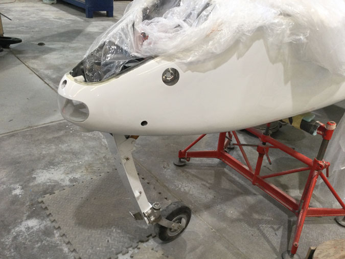
After Paint I found that things didn’t really fit anymore and it was time to sort out some nose wheel issues too.

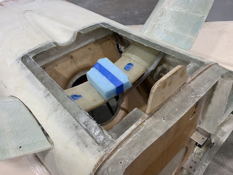
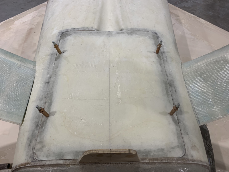
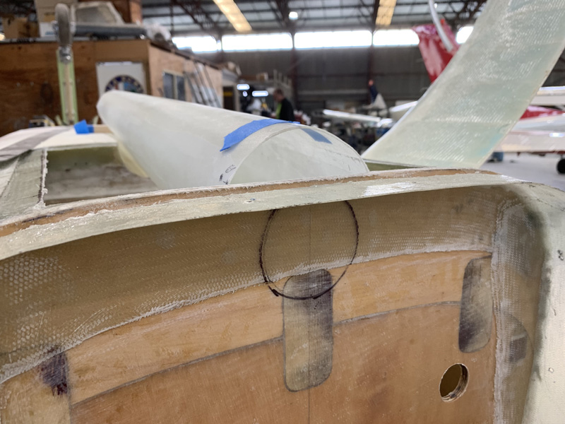
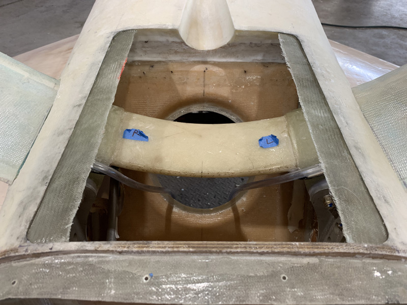
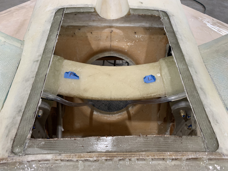
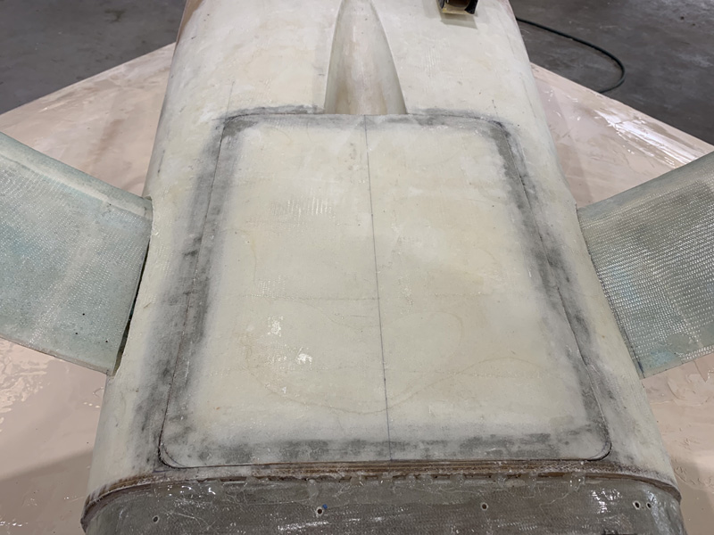
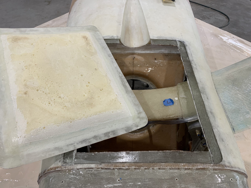
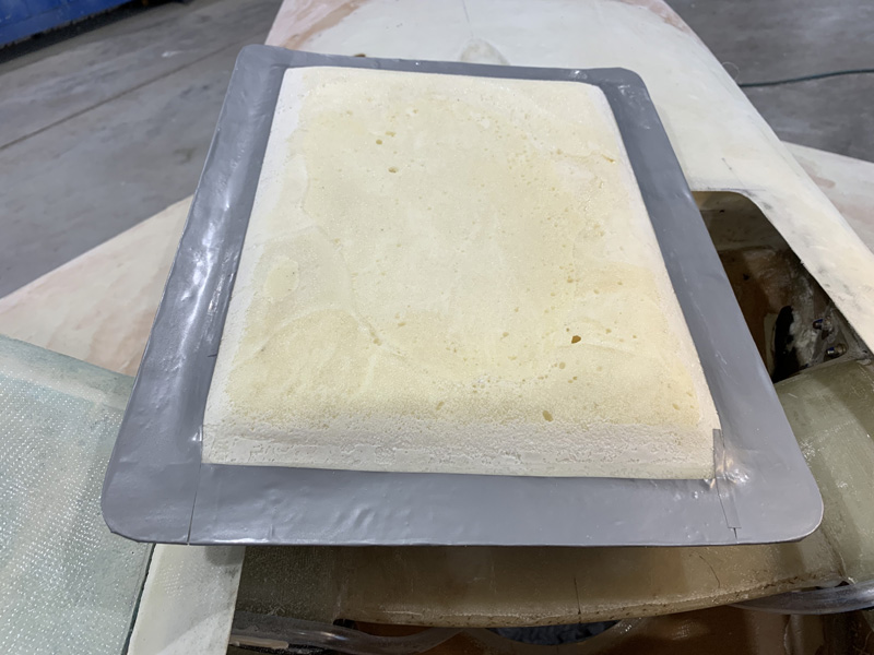
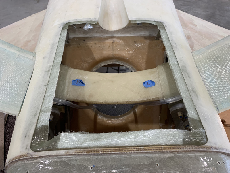
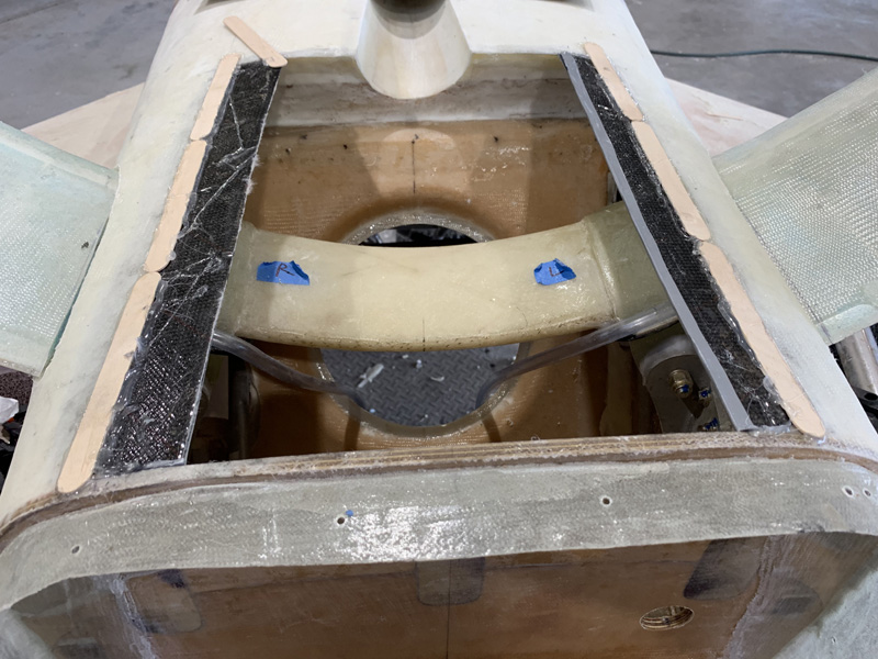
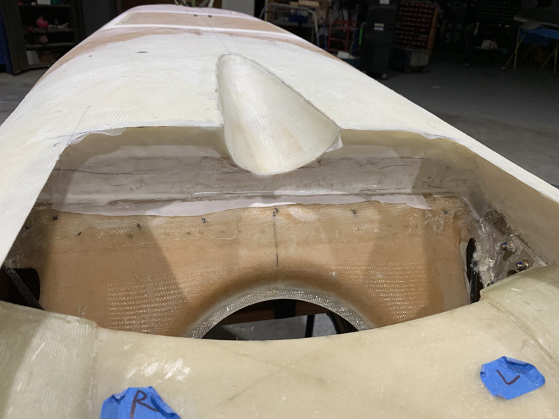
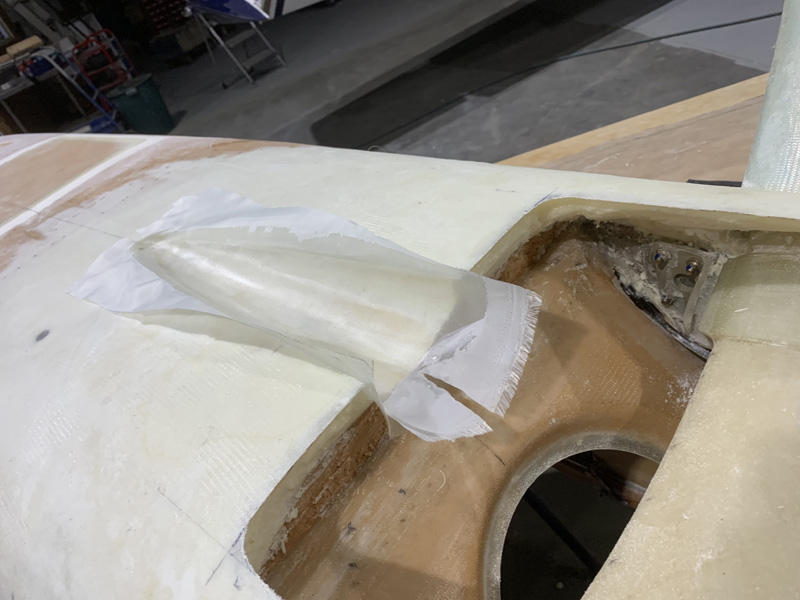
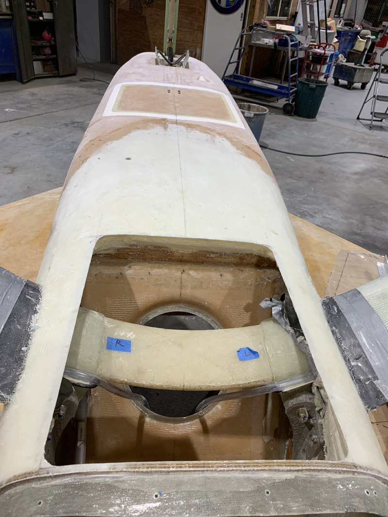
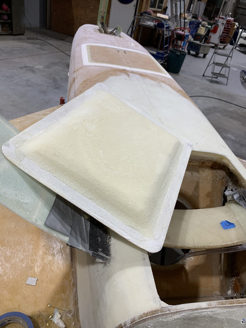
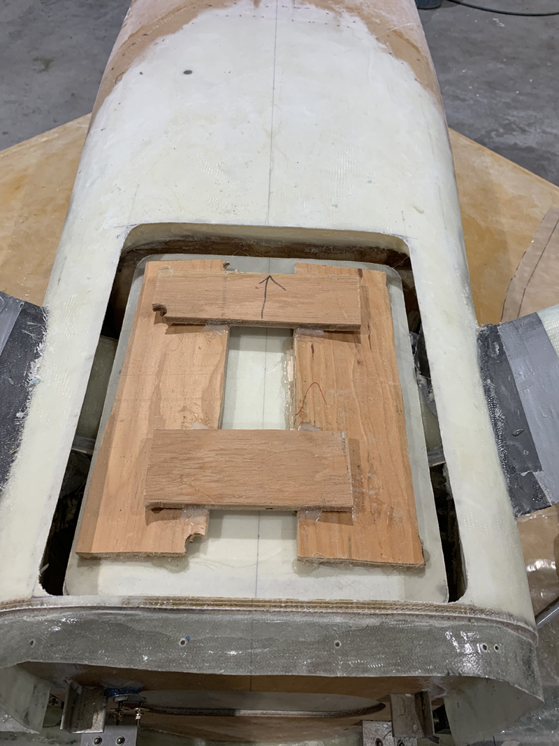
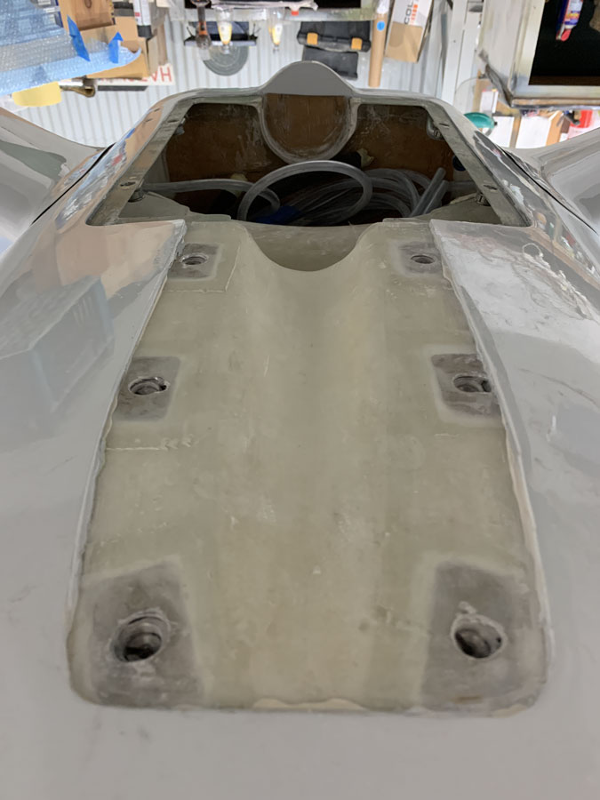
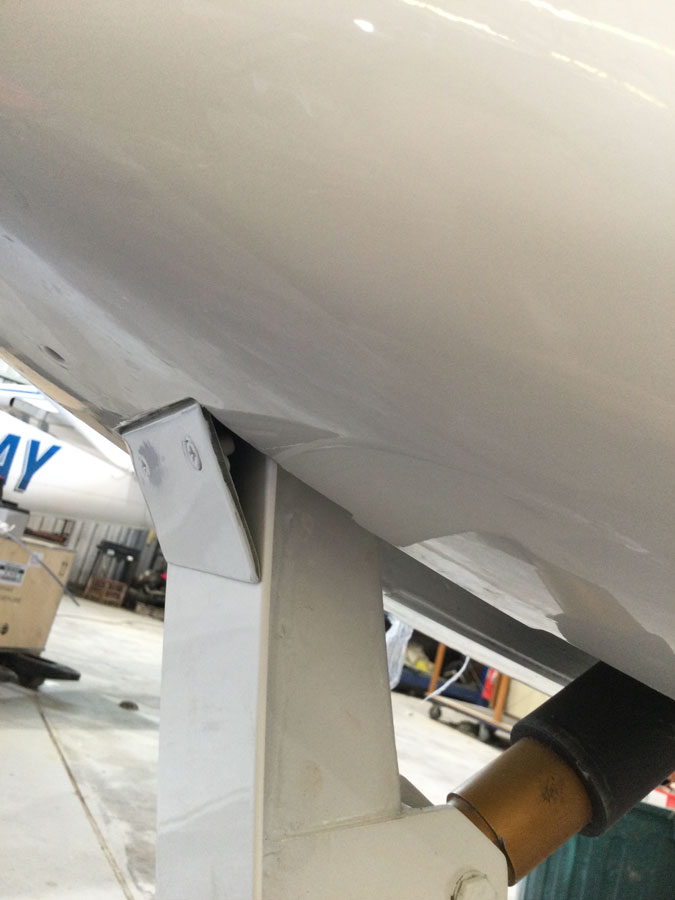
After some work the hell hole hatch fitted again.

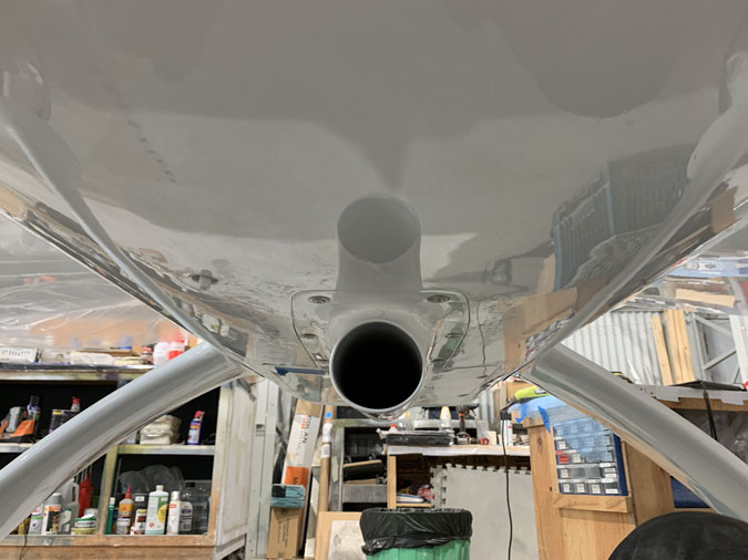
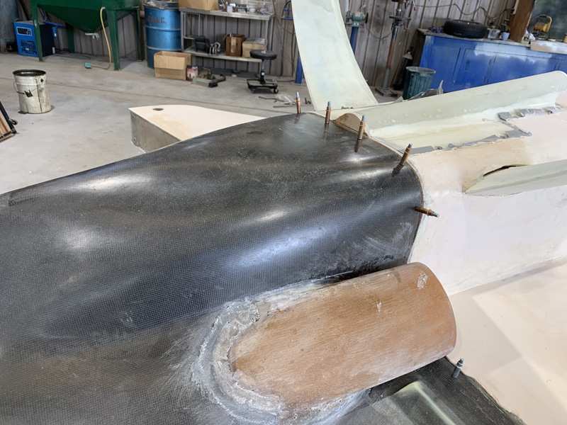
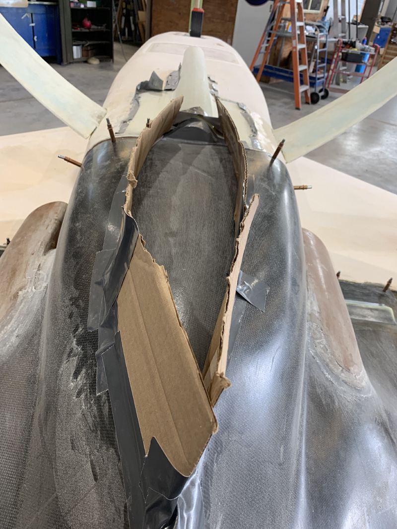
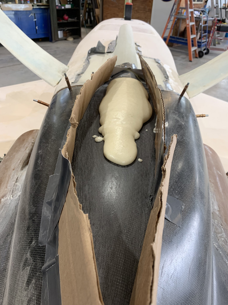
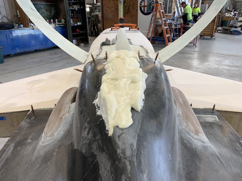
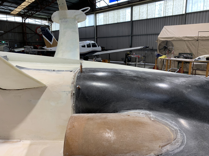
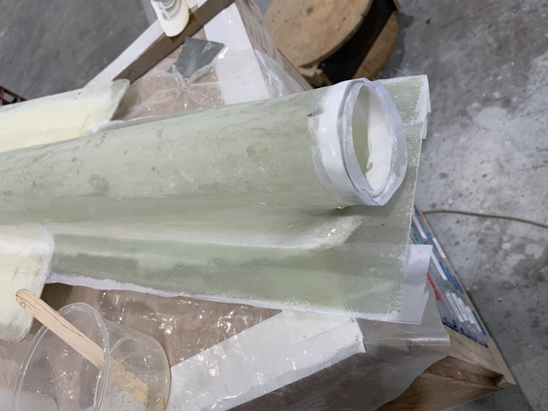
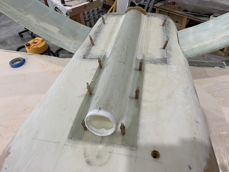
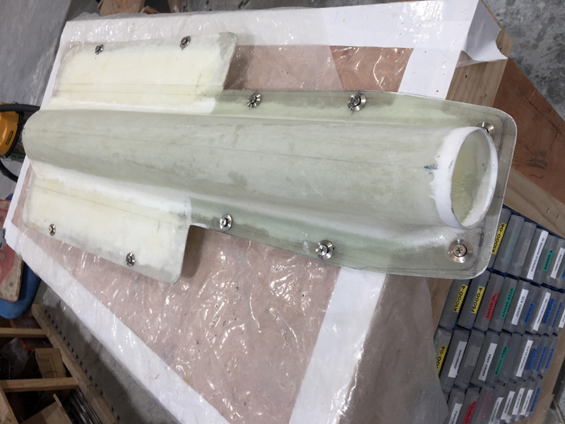
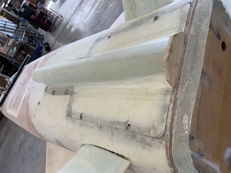
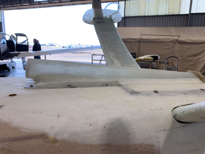
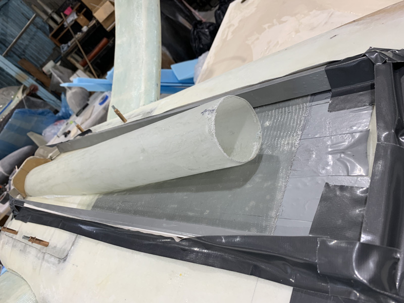
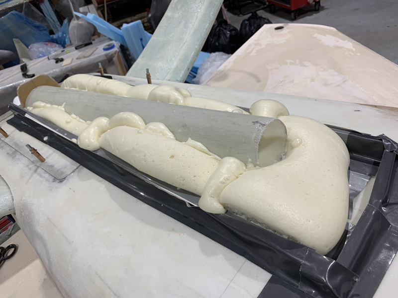
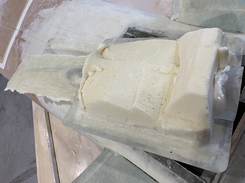
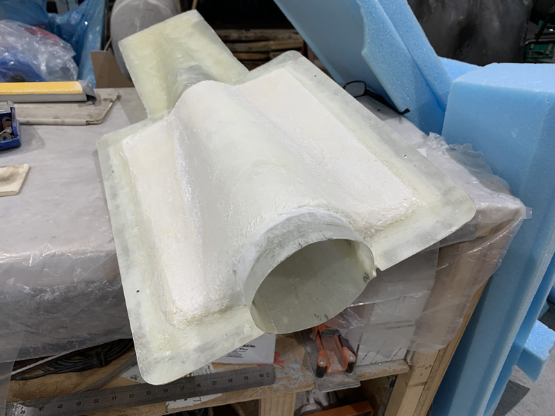
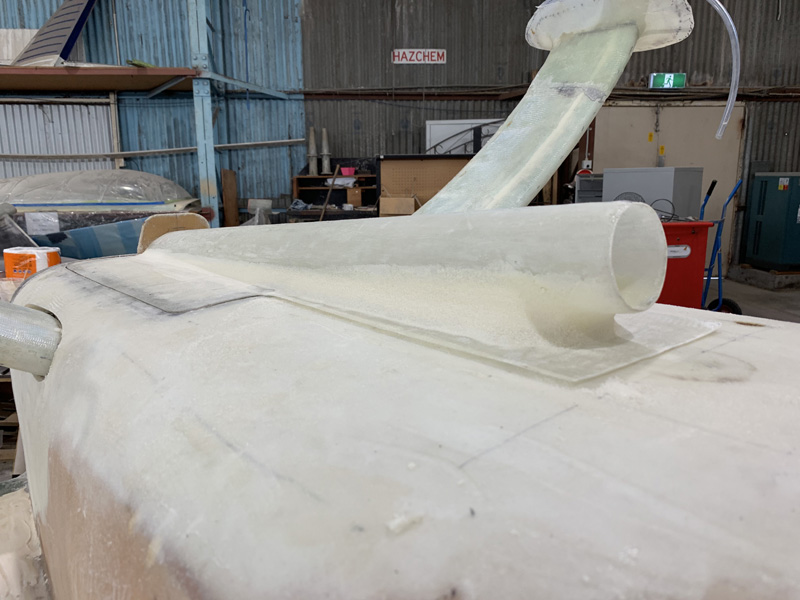
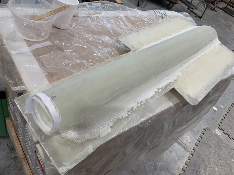
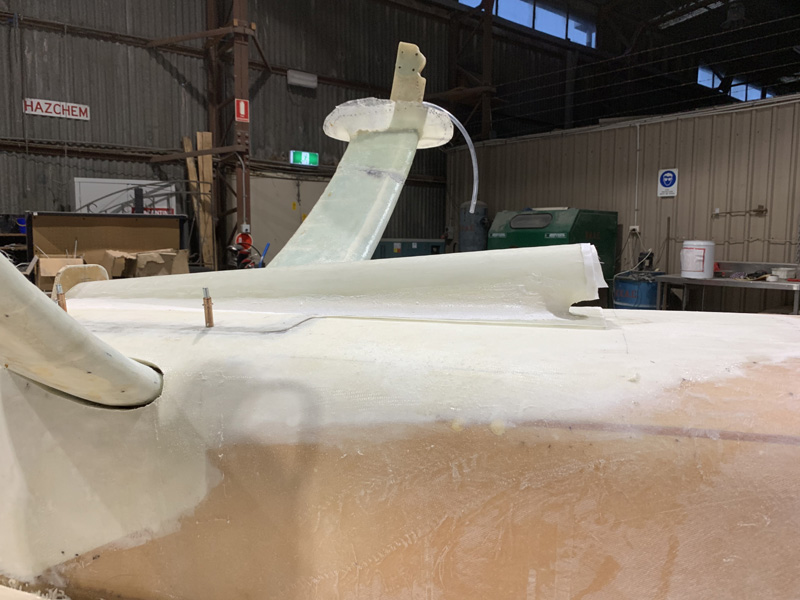
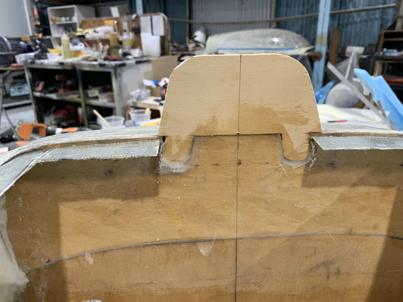
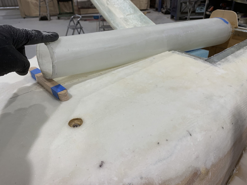
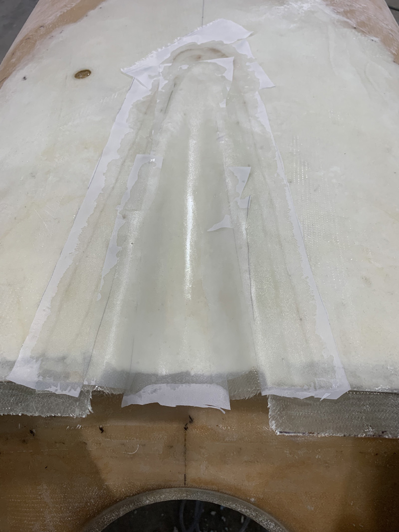
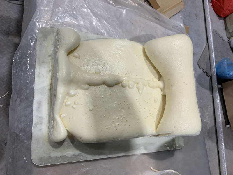
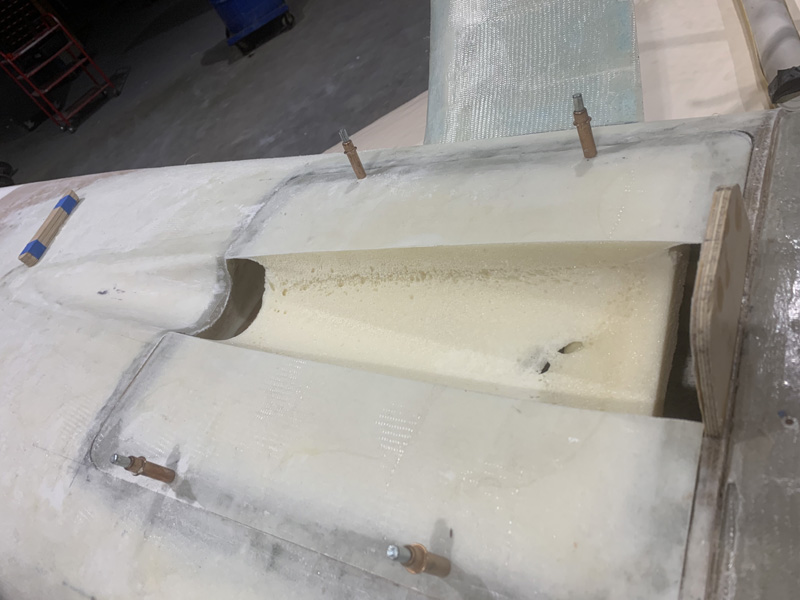
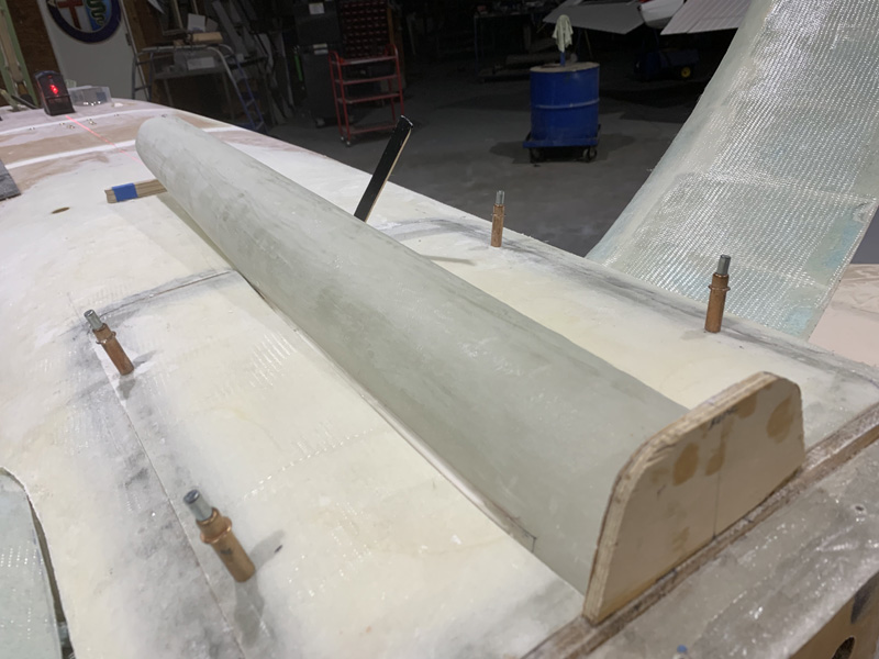
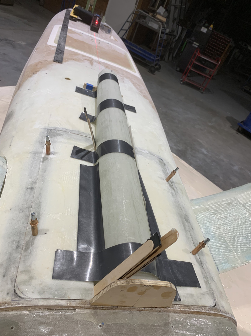
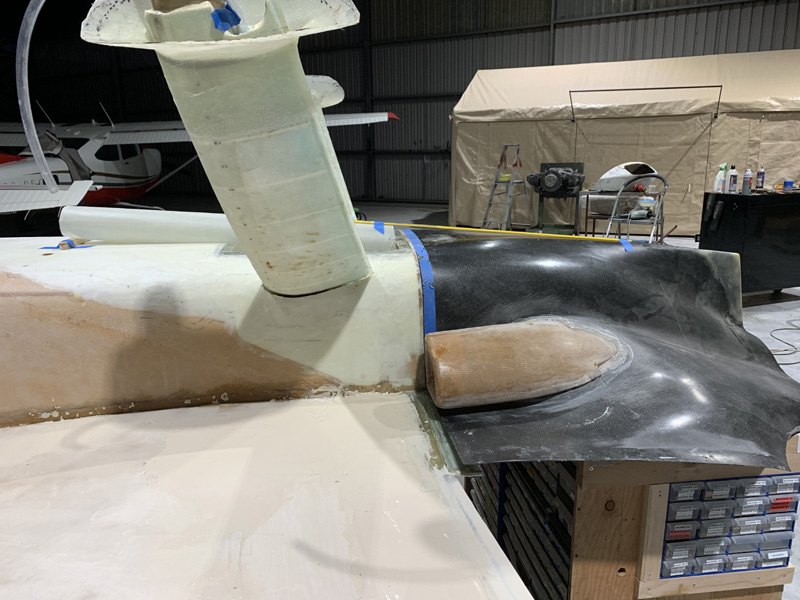
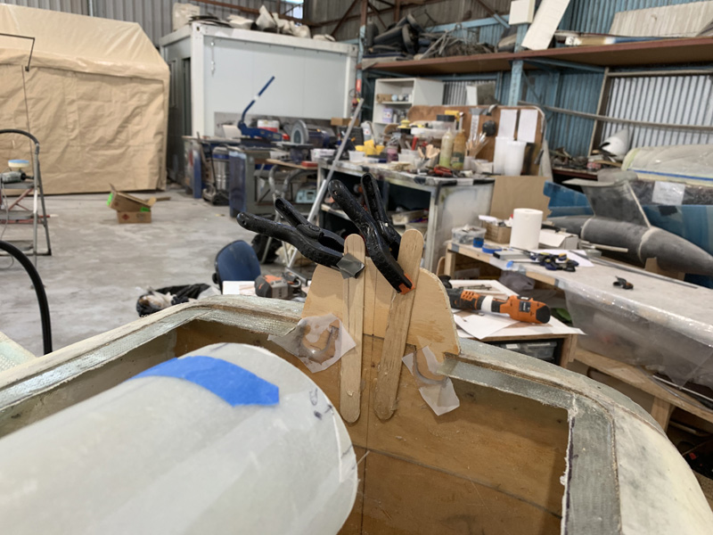
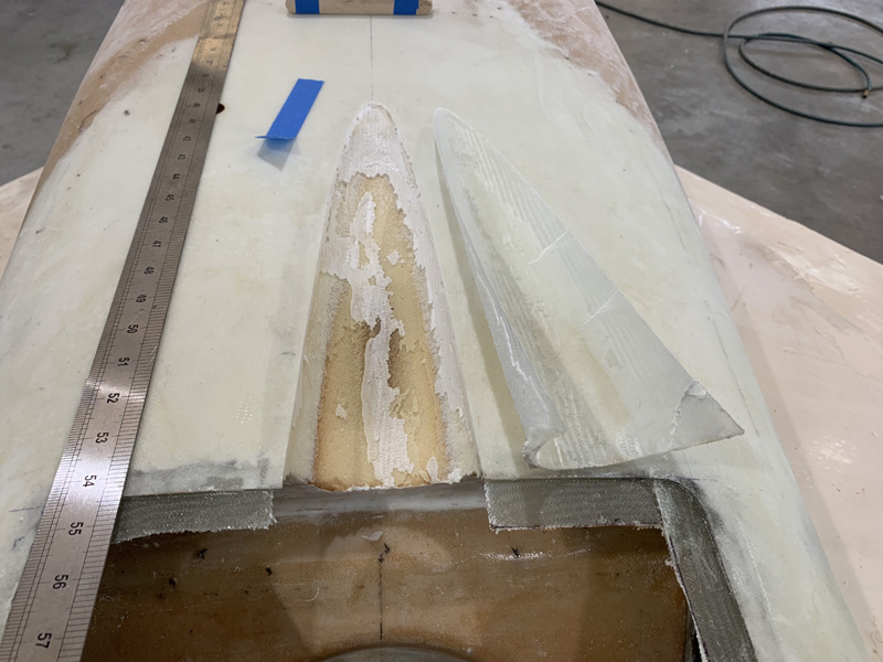
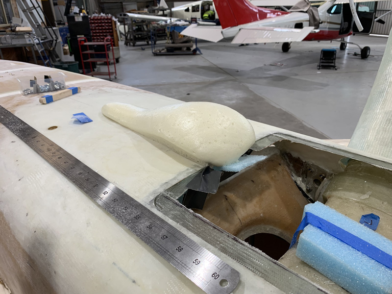
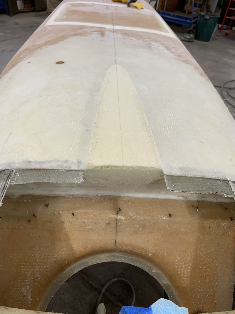
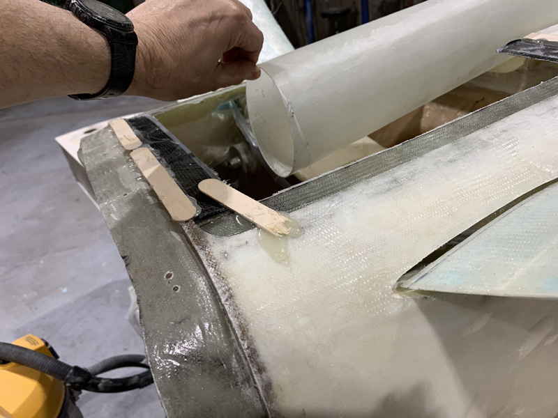
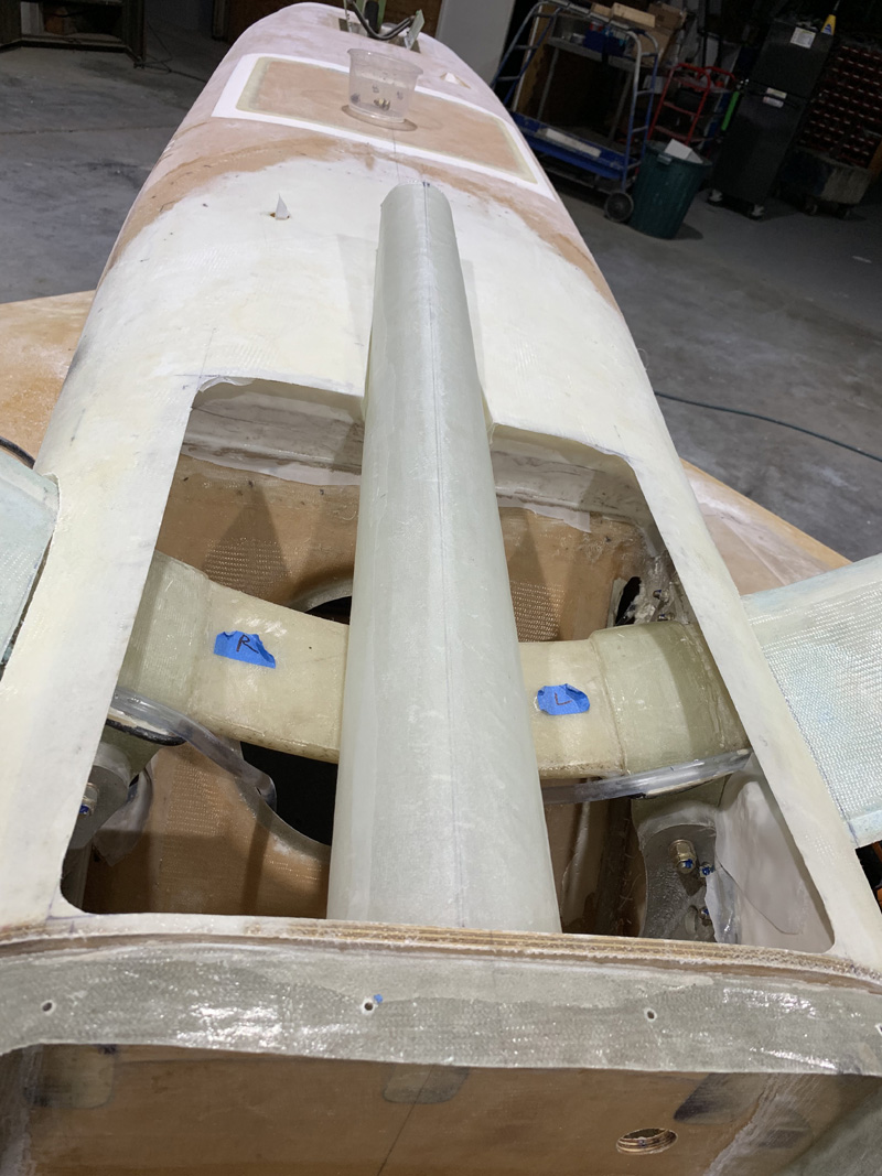
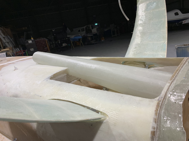
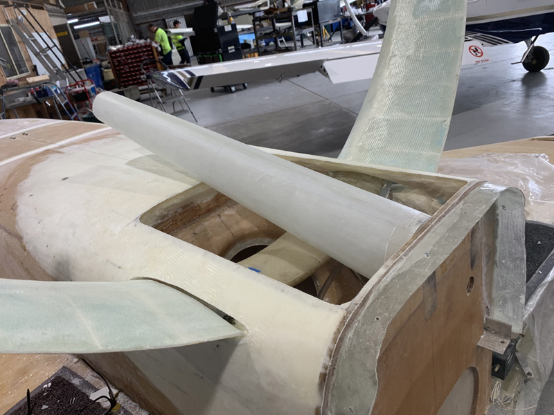
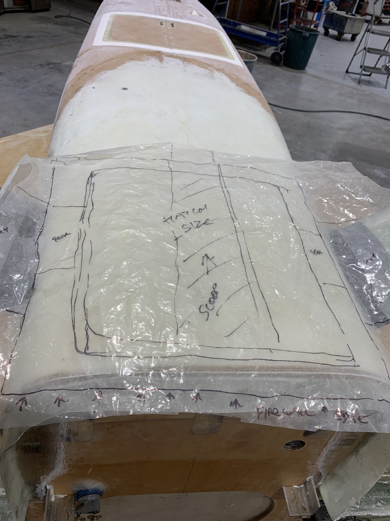
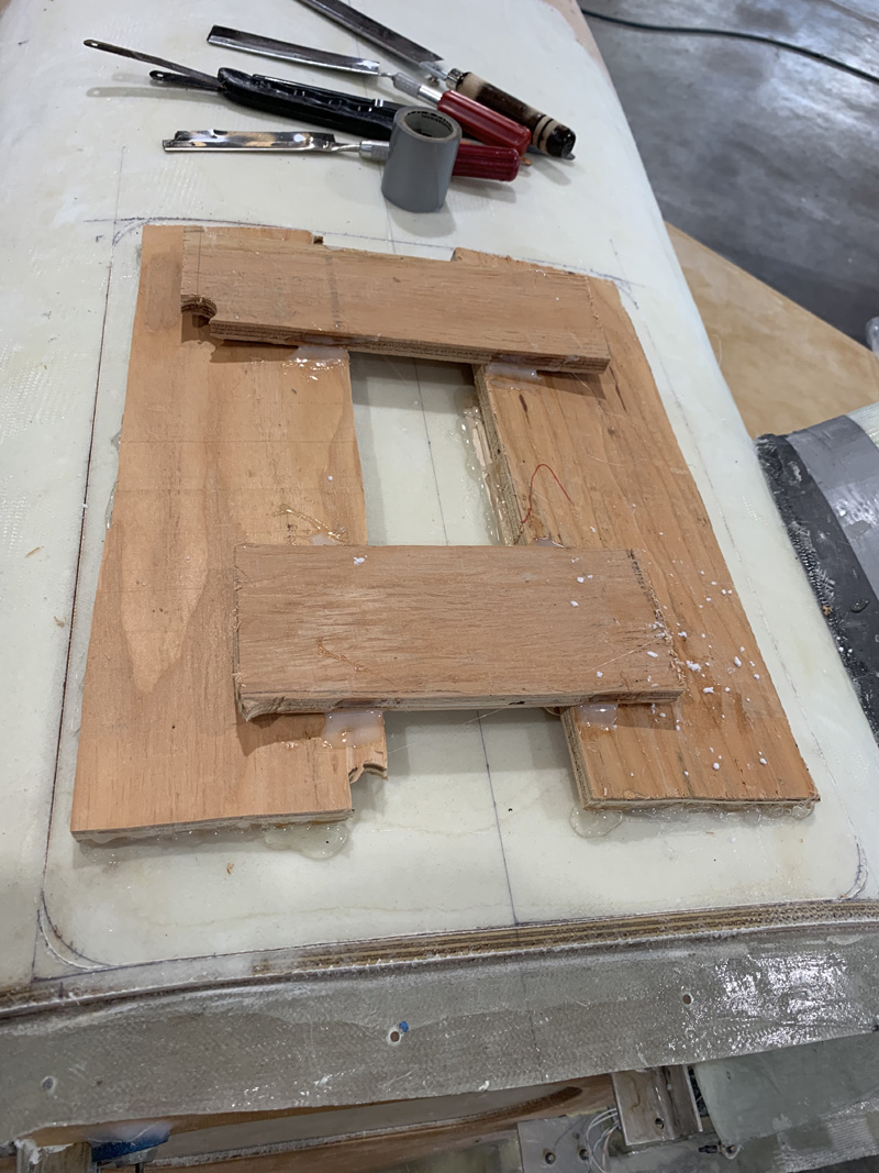
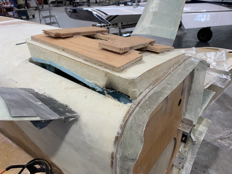
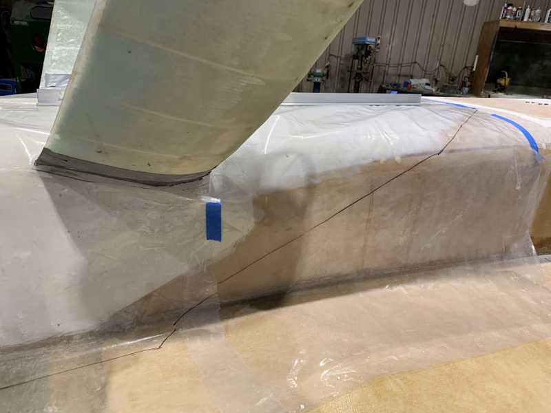
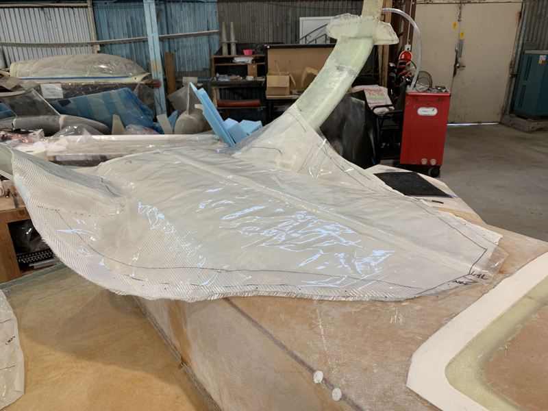
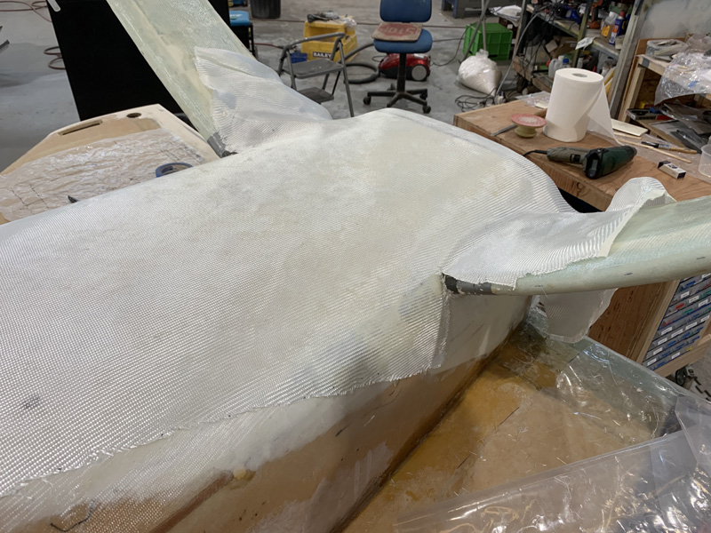
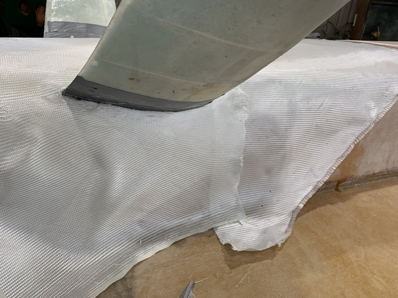
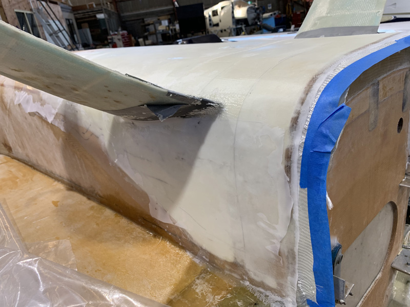
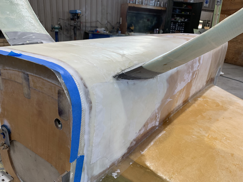
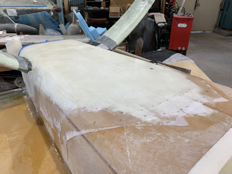
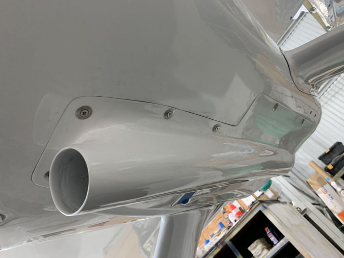
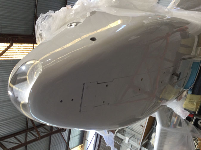
This RAM air scoop is another experimental modification that I hope pays off.

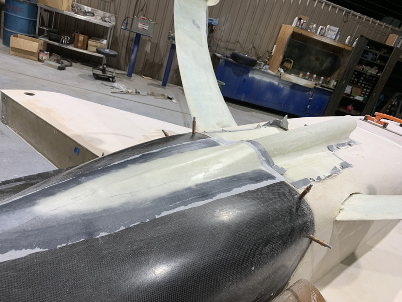
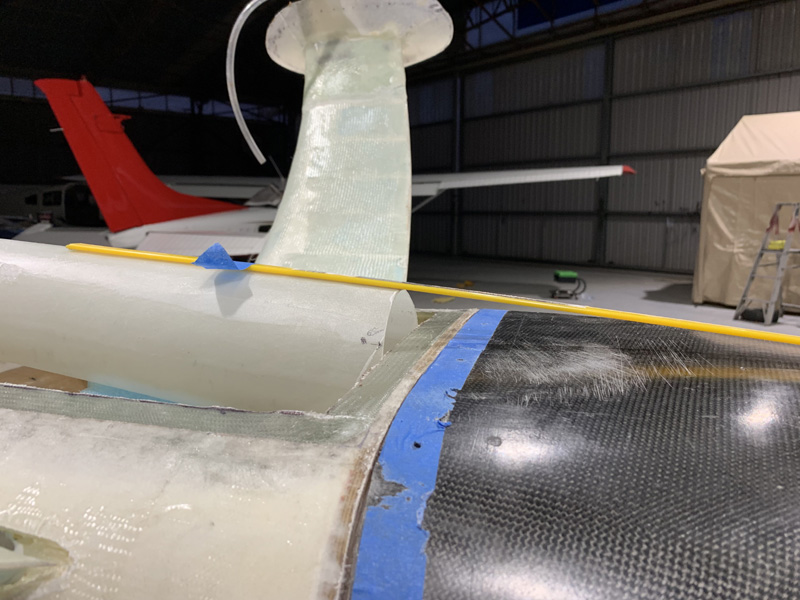
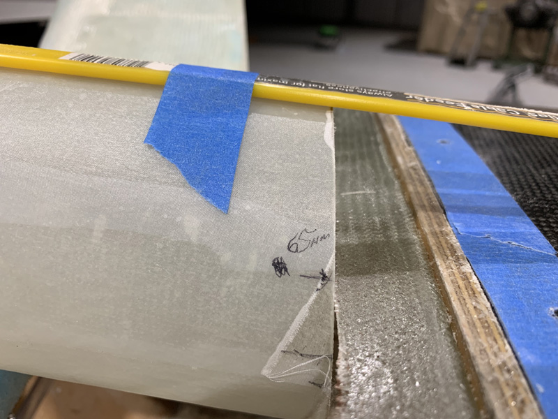
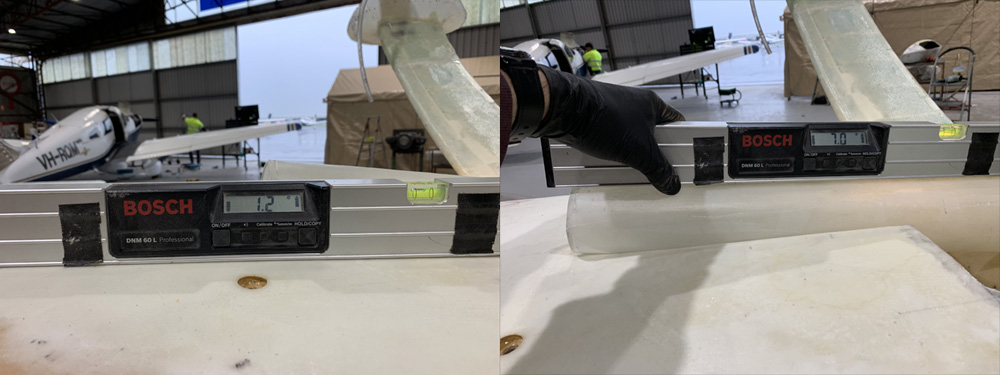
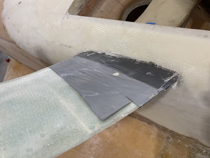
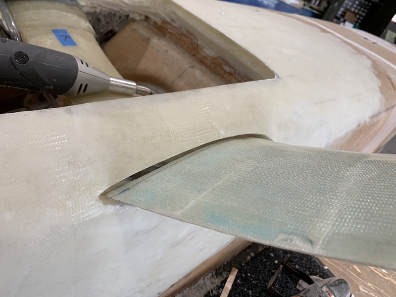
A lot of careful sanding got the paint boarders back in the ball park.

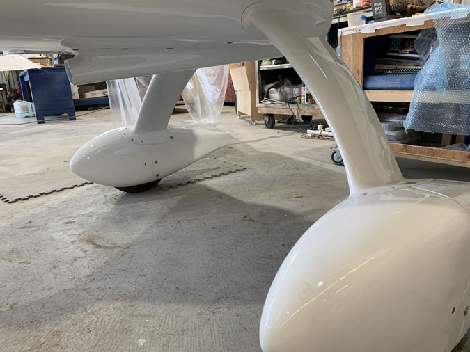
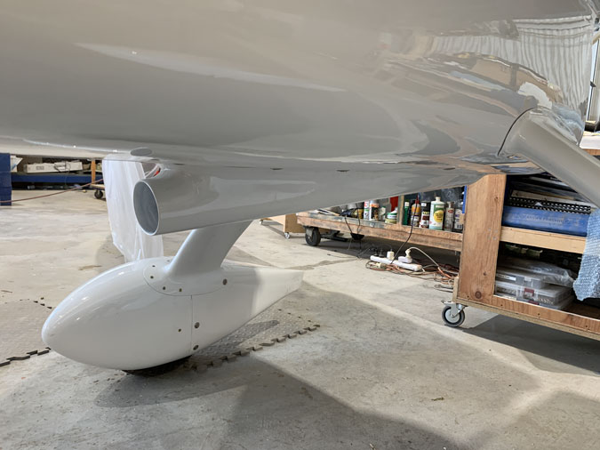
The pants look good if you photograph from the best angles. These took quite a bit of careful sanding to make them fit again too.
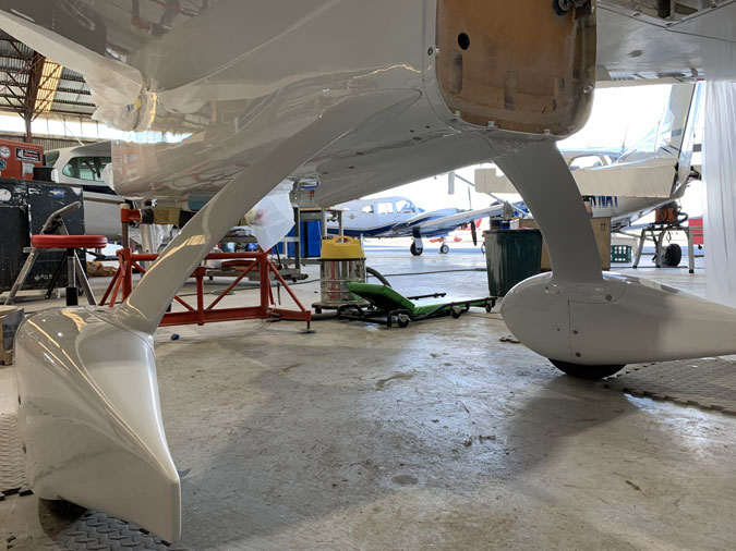
They do look good.

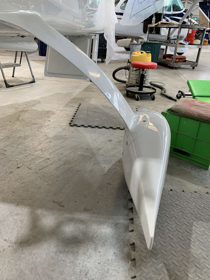
A reasonable fit and the lines are nice.

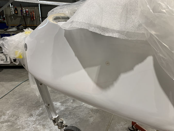
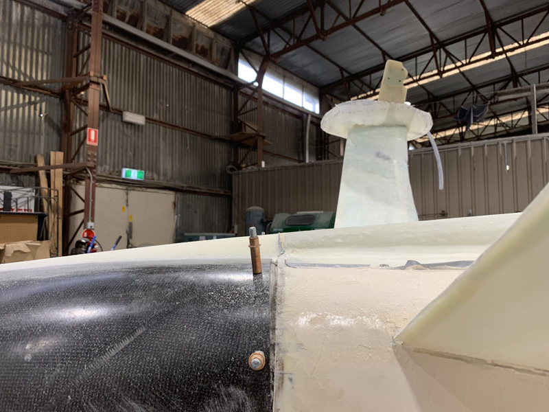
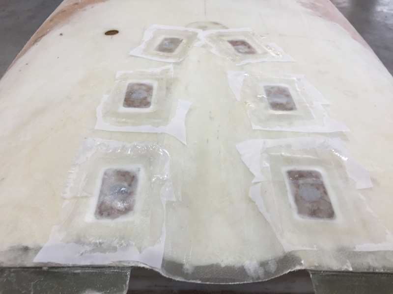
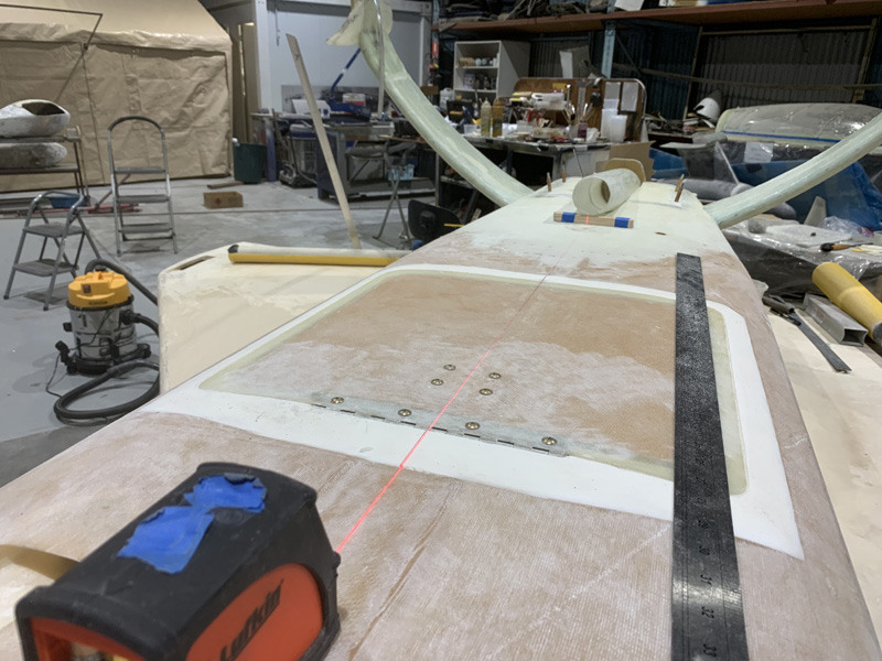
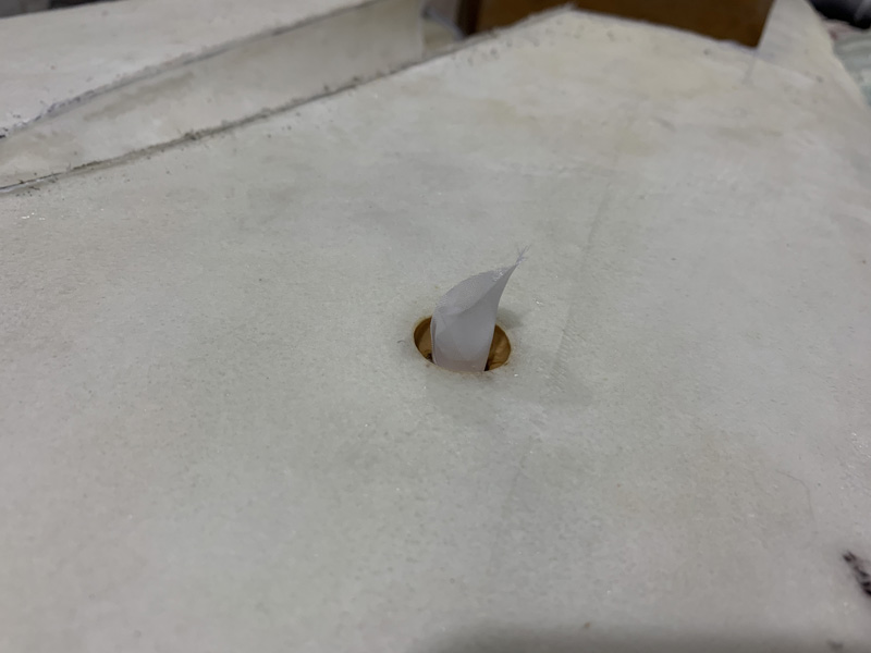
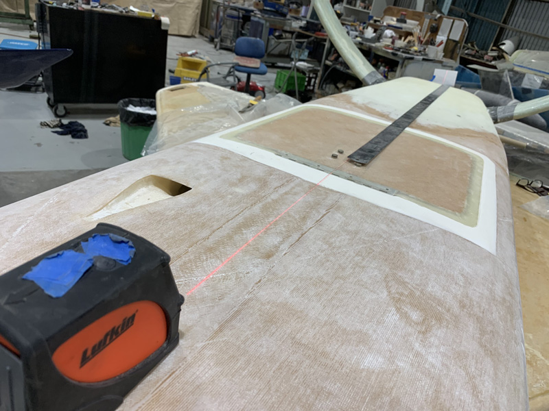
Another little job was to get the static vents placed.

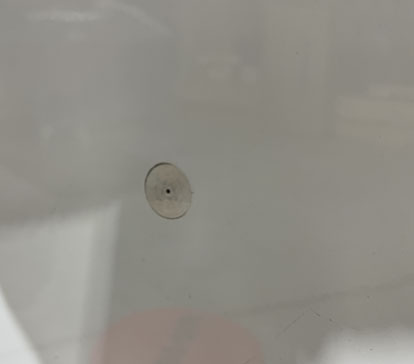
Here’s one side installed. They are just press fitted for now. It will get sorted out when we plumb everything and then test fly!

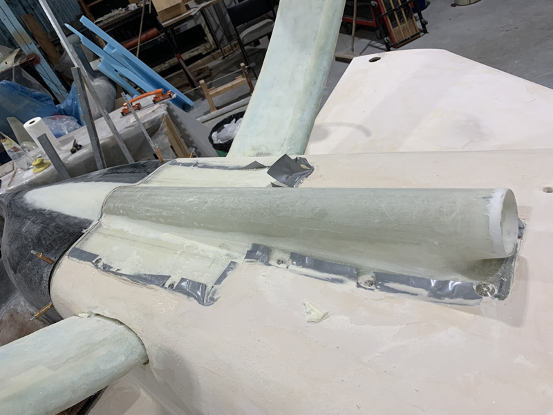
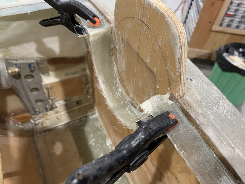
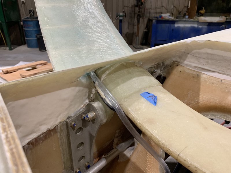
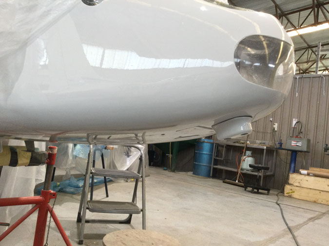
Quite some sanding and fit work was needed to get the nose gear happy to retract with its Garolite G10 nose shield, now painted, in place.

This little spring loaded cover needed a fiddle as well.

I have a nose bumper and thanks again to ‘Marco’ who made it for me. I can’t say who Marco is as he doesn’t want the world to be asking him to make them more nose bumpers. So don’t ask me OK? He does great work.

Quite a bit more work went into this nose gear. It had issues. Lateral play side to side. I had to get the AN5 bolt out holding the NG6A and it was a nightmare. I ended up making a special tool just for that and spent more than a full day trying to stay …cool.

The side to side problem was because the mushroom spacers that came with the NG6 I had purchased were a little too long. There were also a sloppy fit for the AN5 bolt. I got a precision bolt and then had new spacers machined up and those a fraction less in length. Long story short… its rock solid now.

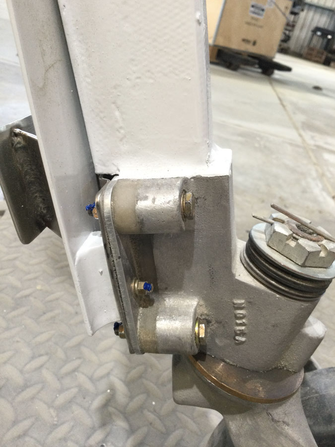
This part seems OK and has a mod I must have documented somewhere in this blog!

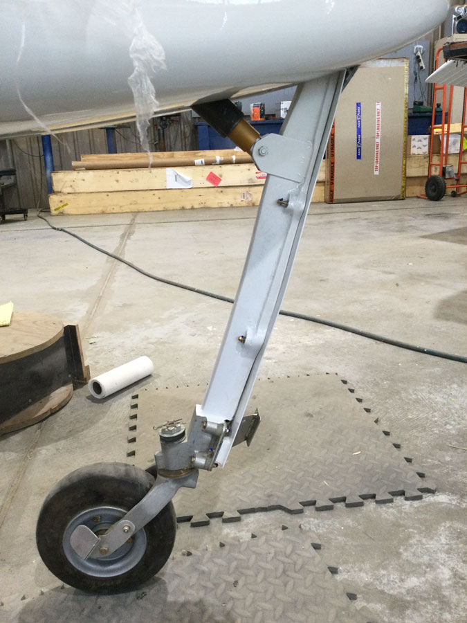
The next problem was the side to side play at the wheel. WTF?? I had purchased mushroom spacers for this too that matched my wheel. NOT! These got a tickle on a serious lathe and after adding a the AN960L washer my nose wheel was also rock solid.

Scoop to Cowl Fairing

Date:  06-22-2019
Number of Hours:  9
Manual Reference:  no ref

Yet another job on the list after extending the firewall down for the second time earlier, was of course, the need to deal with that.

You can see here that now I’ve trimmed the firewall down to the scoop edge there is still the need for a tapered fairing on the cowl bottom.

I decided again on pour foam and went for a bit of a structure like building footing to contain the fun mess it makes.

My first pour came out looking very much like a platypus. Being an Australia build I can only say it is appropriate.

Subsequent pours ruined my art work but it did give enough material to work a different kind of sculpture.

After very careful carving I had my fairing shape.

I went for two ply of BID with the second ply 0.5″ narrower on the sides and rear. The usual peel ply went on top.

With the fairing now glassed I have a result I’m happy with.

From another angle you can see there is still plenty of fill and fair work to do around the scoop hatch.

Scoop Fasteners

Date:  06-10-2019
Number of Hours:  16
Manual Reference:  no ref

Over this last week I’ve been sorting out this RAM air and hellhole cover while still sanding and filling the underside of the strakes. Thats the gift that keeps on giving.

I felt the sides of the ram scoop at the base were not strong enough to hold the hardware so this received another 3 plies a side. I had previously glassed over the ‘scoop to base’ edges as well.

After quite some thought I positioned where the fasteners had to go and clicoed the scoop in place. All was good.

Next up the process of making the nutplates you see above, I have an alodine pen as well which was an easy way to get a coating done. I did roughen the plate surfaces as they will be bonded to glass and micro. I used a router and cut the position slots by hand. Then it was a little more time positing the scoop to ensure I had the foam receiver spots in the fuselage big enough.

First up was to micro in the Camloc receivers so to ensure I could get the scoop off after the cure.

Once the top was off, I added a little more micro around the nutplate edges and then two plies of glass and peel ply. These are not going anywhere now.

The scoop and hatch top assembly could now get a little tidy up. You might notice I have a bell mouth entry made for the narrower end of the scoop. I’m told this will assist airflow.

In place with the Camlocs positioned. They will get a final fit after the filler is done.

I do have a bit of a lip to blend in from the top. I could have easily made a joggle but didn’t think of it. That would have been better than having to fill and fair in a more ‘fulsome’ way. If you are about to build a scoop and reading this, I’m sure you will do better. There is still a fairing to build on the cowl bottom before I trim the end of the firewall. We are pretty close to having this scoop and lid all done.

Scoop and Hellhole Cover 2

Date:  06-02-2019
Number of Hours:  15
Manual Reference:  no ref

Over the last few days the scoop plan is coming together.

Given the scoop is now microed in place onto the hatch cover, I now needed a base to build the fairing onto. This base has to join to the hatch but not to the bottom of the fuselage. I went for two ply of BID and the usual grey duct tape for release.

I then got creative with the idea that if I introduced the pour foam while the glass base was wet something good would happen. Yes the foam as it expanded would push the glass onto the base of the fuselage and reduce the air gap that may have happened otherwise.

As it turns out this worked about 80% but I had several hours of getting the newly made cover base released from the fuselage. It came off eventually with no damage.

This seemed like a good time to trim the inside foam of the hatch lid to something more manageable. When this was done I gave it a coat of micro to act as a hard shell for when I glass this underside.

Yes while all this was happening and I have also been doing the fill and sanding of the stakes. Another need was to make a lip for the scoop to seal against. The initial layup was done from under the plane through the hellhole. Not ideal. I’ve followed up with a three ply reinforcement as you see above. The fit is excellent.

More time in blending all that pour foam into a minimal side fairing.

Once shaped I have again gone for the micro hardshell method. I’ve added a little meat to the entry point as well, I want to make an optimal edge here.

This is a side view to show the angle of the scoop to the fuselage bottom. Its a compromise of the 2 degrees nose up fast cruise angle, climb angle and minimum wetted area for the fairing to cowl intersection.

Scoop to Hellhole Cover Stage 1

Date:  05-29-2019
Number of Hours:  11
Manual Reference:  no ref

Over two days I have the scoop first stage install done.

Here’s how I added the required height (or rather depth) to the firewall. Adding those ears made it rock solid after cure. Even so I added two plies of BID later just to be tidy.

With the plane’s bottom filled in, I had my third go at getting the scoop sitting where I now want it. All good.

With the trough correct I again glassed it with two ply of BID. This time I softened the edges and went for a blend with the bottom of the fuselage. The plies were a graduated overlap, which you might notice in the pic, like a structural repair.

I did feel that my hatch lips at 3 ply were not strong enough. Here you can see I’ve added another two plies and clamped them for the cure. Is this a gaggle of clamps? Google tells me there is no collective noun for this.

Post cure. It may look the same but the lips feel stronger and my cutaway for the scoop is nicely blended into the planes bottom.

Here’s a problem. When I add the scoop the hatch will have to be cut in half and a big bit taken from the middle. If I do that then the sides will be separated and all over the place. The solution is good old pour foam. This will supply a bridge between the two sides while I remove the middle. It will also be a base that, after some trimming, I can glass over to make the scoop placement much stronger with only a tiny little weight increase. I hate weight increases.

Besides that, pour foam is fun.

After tweaking the foam on the other side, I was able to get the hatch down and clico’ed in place. We are ready for the big cut.

This took more than a couple of hours but I have a really good base that the scoop fits to now.

I did a trial fit and went for the laser to ensure my scoop is straight. The mixing sticks tied together with blue tape are to ensure I keep my .8″ gap at the mouth of the scoop.

I mixed some West epoxy and did the usual prime and then added in lots of micro to make a paste for bonding the scoop to the hatch. It was 8C in the hangar which is NOT good for epoxy, thats why I went for the West and the fast hardener. Its a non structural bond, just glass to foam. I’ll go the regular epoxy for the rest but using a heat tent. I do not like anything below 15C and ideally anything structural needs 26C. That was easy at home but now I’m in a hangar I might as well be outside except for the rain protection.

As I’m leaving this overnight, the tapes and sticks are to ensure the scoop stays put!

Total Scoop Rethink

Date:  05-26-2019
Number of Hours:  10
Manual Reference:  no ref

The scoop position where it ends below the level of the firewall was just not going to fly. It felt wrong, looked wrong, (although aesthetically OK) and I was having to try too hard to justify the design.

Here it is again. This is position and angle are not OK.

Out came Hoerner’s, ‘Fluid-Dynamic Drag’, the Bible for these sort of issues.

Displaying image.png

OK, so while my flush mount scoop is great for minimum drag BUT further reading tells me it is pretty poor for getting the air at the end of the scoop pressurised as I slow it down. In fact it has significant losses and so reducing the gains I was aiming to achieve by about a third. That’s not to mention that all the pictures of airplanes with various scoops ALL have them offset from the bottom of the fuselage.

How much offset was my new question? Well we want to be below the boundary layer and in free stream air. OK, so how thick is the boundary layer?

That depends on how fast you are going and how thick the air is and how far back from the tip of the nose you are. Grrrrr…  This relates to a dimensionless number, a ‘Reynolds’ number (Re).

Re = speed x length / kinematic viscosity
Re = 6378 x fps x length
1 knot = 1.68781 fps 6378 x 1.68781 = 10765

say 180 knots =  10765 X 180
Re = 1,937,700
so square root is = 1392
(we are assuming sea Level for the Re)
Nose to scoop is 8’4″ or 8.33 (100″)

Delta (thickness)/distance = 5/square root of the Re (derived from experimental data many years ago)
Delta = 8.33 x 12(convert to inches) X 5/1392 = Boundary layer 0.36″
We also want to allow for different AOA’s when climbing and Density Altitude which effects the Re

Which all makes me think .75″ to 1″ is in fact a good enough distance, even a bit more than necessary perhaps. JZE ( my flying EZ) is about 2.6 degrees nose up at 140 knots. So we are looking at 2 degrees up at 180knots at a guess. Our scoop can be that much offset from the bottom angle.

Yes 4.9 less 2 degrees = 2.9 degrees, more than ideal. I get that. In the end I opted for 0.8″ offset at the scoop entry as a sweet spot for making the angles look correct and being well below the boundary layer. The 2.9 I believe is still a reasonable compromise with all the other factors in play for angle to the relative wind.

That 4.9 degree angle from the bottom of the plane works pretty well for blending to the fuselage. A little extra I think is good when climbing and less than three degrees offset for the free stream air to deal with I think is acceptable.

We also have to deal with the air coming off the scoop bottom onto the cowl. We need a fairing where the yellow line is marking. I also need to deal with my suddenly too short firewall!

The next issue is how to hook up to my 65mm OD intake for the engine. Here you can see I’m thinking that if I get this 65mm or close to it above the line of the cowl, then I can leave the cowl bottom as it is and just add a fairing on top.

This is roughly where I plan to plumb the intake for the engine from the RAM air. Of course an air filter goes in there first.

Here I’ve already (I tell myself I am fast when it is all going smoothly) added to the firewall at the bottom (top as the plane is inverted in this picture). I’m using the same marine ply and just made a piece with two fingers at the top (or bottom in the pic). I have inlaid them into the existing firewall and used epoxy as well as a few sticks to keep it in place. I will soon add glass to strengthen the bond.

Meanwhile, my second effort in fitting the scoop is now far too deep. I pulled out my careful glass shape and also removed the micro. There is zero need to add more weight by being lazy and just filling in the scoop as is.

Once cleaned up I added pour foam which did its thing.

About 10 more minutes work and I again have  a clean surface for my third go at fitting the scoop to the bottom. Wish me luck!


Hatch Lips 2

Date:  05-25-2019
Number of Hours:  4
Manual Reference:  no ref

The hatch lip building continues now to the top and bottom.

After removing the carbon molds or ‘former’s’, the sides worked out OK.

I again used sticks and carbon strips to do the front and back and of course tying the front and back edges with the existing sides.

After cure this worked out OK. It would have been much better to have the top in place when these lips were done. In that case the new pieces would be molded to the top and an even better fit.

As it is, the top does fit and with fasteners I should get a more than reasonable result.

There is still plenty to do on this induction ram air tube and hellhole lid.


Hatch Lips 1

Date:  05-24-2019
Number of Hours:  14
Manual Reference:  no ref

This edition of ‘hatch lips’ includes another epic fail.

Just before moving on to the hellhole cover lip… I really needed to be sure what I was doing with the RAM air scoop position.  If the fuselage was at 1.2 degrees and the scoop sitting at 7 degrees, then my scoop is 5.8 degrees to the bottom of the plane AND it would be 3.8 degrees to the relative wind. Ideally it would be zero to the wind but I’m OK with the 3.8 and I think it will still collect the air for the engine as I want it to. The main thing as I understand it is that the air entering the scoop would not go turbulent.

Time to make lips for the hellhole cover. The hatch lip had previously received an extra 3 Ply around the edges and feels quite stiff. My plan was to get the top in place and then layup the tapes from underneath through the hellhole backseat opening.

Oh, while I was at this I did do several hours on the strake undersides over two days and have put on the first coat of filler. That’s not worth its own log entry so I included the hours in this one.

I did a very careful 3 ply layup for the four tapes.

I positioned them as you can see above and then carefully placed the taped hatch lip in place and hot glued it flush to the edges.

I then found all the tapes fell out and I couldn’t get both hands in from underneath to properly reposition the wet lip edge layups. I had several tries…. and then called it. Epic Fail. See the picture above…

I gave up on all that work and went to think of something else. I am not a perfectionist by any means, however if it isn’t going to work I will scrap what I’m doing and get on with a better method straight away.

Method B. I had some carbon scraps from the cowls that were about the same thickness as my hatch lid edges. I have hot glued some sticks to the top edges and then fitted in these spacers with grey tape on the bottom.

You can’t really see but I have done a 3 ply layup on the bottom of these carbon pieces and the hatch edges that are 2.5″ wide and span the inside to spacer former to make a lip. I will do the front and back areas tomorrow when these are cured enough to continue. I hope the hatch will sit flush with the edges or I will make adjustments. This was an easy layup compared to trying to do it though the backseat access hole.


Interior hatch Clean UP

Date:  05-22-2019
Number of Hours:  6
Manual Reference:  no ref

Another short day of small jobs. I cleaned up the partly cured edges of the scoop and hatch from yesterday but give the epoxy was still a little soft I moved on.

I worked on the hatch interior. Mainly getting the foam so it would blend with the hatch edges and I smoothed it out where I could. There are several areas that are just not accessible. I did my best and then used thick micro to plug the surfaces I could reach and then peel ply.

While its a little rough I did choose to hard shell. Tomorrow I’ll add some glass where strength in needed on this inside hellhole area.

Not prize winning here either. It will be made strong with some glass layups and I have great access.  It is best to do all this now before a hatch lip reduces the area I have to deal with these insides.

Another small side job today was to deal with the sump fuel drain. I dug up my position holding plug carefully and then did a flox corner type of foam removal around the circular hole. I then very carefully applied pure then micro using the fuel safe EZ epoxy. I finished off with some peel ply to prevent the micro sliding into the hole and mucking up the threads. The drain will be proud of the bottom unfortunately. It is at the low pint in the sump where it has to be.

This is where the scoop will go and you can see the challenge ahead where I will have to cut into the hatch to make this all fit and be removable.

Another view of the scoop. Yes it is always dark now when I leave work.

More Hatch Jobs

Date:  05-21-2019
Number of Hours:  7
Manual Reference:  no ref

Three hatch jobs today.

While I’d glassed the gear into the sides now is the time to make a gap so the gear can flex without damaging the exit point.

This took about 30 minutes to make the gap and then another 150 minutes to get the tape out I had left in to protect the gear. My bad. There was a LOT of foam in the way.

Next up was to look at the scoop again.

Here I have re-cut the scoop slot for a good angle just below the bottom of the firewall.

After a flox corner I used 2 ply of BID to seal the scoop cutout. I made it a fraction oversized so I can position the scoop later without issue.

The hatch edges here have received a two ply BID layup 1.5″ wide. Once cured this will be strong enough for a hatch lip and fasteners. The original 2 ply layup would not be sufficient. I’ve left the rest bare as I will be cutting into it later when I mount the scoop.

Hellhole Hatch 1

Date:  05-20-2019
Number of Hours:  7
Manual Reference:  no ref

Today was about cutting out the access hatch.

First up I used my rough template to reestablish where the internals of the hatch are so I could place the outlines where they need to be. My template didn’t need to be pretty or accurate, just act as a set of x-ray eyes.

I do however like a center-line in the middle. The laser helped to continue existing lines after my layups had covered the old ones.

This photo is after I have cut the hatch outline, of course I first spent a while drawing it out. After cutting I added a frame to keep the hatch in its curve.

After deepening the cutout as far as I could with a hacksaw blade, patience and wiggling eventually had the hatch out.

There was a LOT of cleaning up to get to this stage.

Here I have trimmed the hatch core to just under an inch thick and down to the glass on the edges.

Of course now this hatch needs a lip on the fuselage side to hold it in place. Plenty more to do tomorrow.


Hellhole Cover 3

Date:  05-19-2019
Number of Hours:  6
Manual Reference:  no ref

I opted for 2 ply of BID at the usual 45 degree bias with the first ply overlapping the second. While it is non structural in that it is only covering the hellhole area I hope that it gives additional rigidity to the landing gear area and boxes in the area leading to the cowls.

There is quite a lot of glass in this layup and I had to work out a way to cut it so the gear legs would be wrapped but the layup not compromised. I used a piece of plastic and got the size and where to make the cuts by playing around with that. Easy.

Having cut two pieces on the floor using this plastic template I did a little more micro fill and then wet out the target area with pure epoxy for the usual prime. Again the plastic was handy for positioning the first ply on the fuselage bottom.

Here’s where I made the first of two cuts around the gear legs.

The second cut was along the gear at the bottom. If you understand what I mean you can see the result here that gives me the one inch or so overlap I wanted.

The two ply layup is now done and that part took a bit over four hours by the time the peel ply was on.

I’m happy how it worked out around the gear. I trimmed the glass at the edges and had a little glass to glass bonding on the bottom of the strake at the rear to tie it all together.

While not that pretty it has worked out very well on the bottom too. Once cured I can do a tidy up around the gear and mark out where the hatch is going.

CategoryLogsHours
All157617079
Uncategorized135
Ch 3 Education220
Ch 4 Fuselage Bulkheads25231
Ch 5 Fuselage Sides32283
Ch 6 Fuselage Assembly30270
Ch 7 Fuselage Exterior14140
Ch 8 Roll Over/Seat Belts990
Ch 9 Main Gear/Landing Brake71642
Ch 10 Canard28287
Ch 11 Elevators36298
Ch 12 Canard Installation12102
Ch 13 Nose and Nose Gear1291097
Ch 14 CenterSection Spar57525
Ch 15 Firewall and Accessories448
Ch 16 Control System27237
Ch 17 Roll/Pitch Trim System654
Ch 18 Canopy70502
Ch 19 Wings, Alierons1271090
Ch 20 Winglets/Rudders71528
Ch 21 Strakes - Fuel/Baggage65437
Ch 22 Electrical System591031
Ch 23 Engine Installation961152
Ch 24 Covers/Fairings/Consoles25202
Ch 25 Finishing561084
Ch 26 Upholstry340
Fuel System46310
Rollover1050
Cabin heating System60331
The Ferry Tank335
Blog2694182
Build Mods2252513
Nose Gear Doors856
Wheel Pants/Gear Leg Fairing40473
Oxygen System762
Roll and Pitch Trim964
Winglet Intersection Fairings445
Baggage Pods11104
Pilot Side Windows437
RAM Air & Hellhole Cover15177
Main Gear Beef Up322
Post Cure124
Fire Extinguisher16
Wing Fences13
EVS (Enhanced Visual System)130
Hinge Upgrade115
Cowl Keeper110
Rudder Gust Locks19
Cooling20607
Taxi Tests42
Flying10

Complete the Test Flight Program

2025/6/30 10:26:01

Round Australia in Four Flights

2026/4/1 10:26:01

Round the World Departure

2026/8/22 10:26:01

Rough River Flyin, Sept 23, 2026

2026/9/23 10:26:01

© Copyright 2025 Dave Berenholtz