• Home
  • Flying
    • First Flight
  • Build by Chapter
    • Ch 3 Education
    • Ch 4 Fuselage Bulkheads
    • Ch 5 Fuselage Sides
    • Ch 6 Fuselage Assembly
    • Ch 7 Fuselage Exterior
    • Ch 8 Roll Over/Seat Belts
    • Ch 9 Main Gear/Landing Brake
    • Ch 10 Canard
    • Ch 11 Elevators
    • Ch 12 Canard Installation
    • Ch 13 Nose and Nose Gear
    • Ch 14 CenterSection Spar
    • Ch 15 Firewall and Accessories
    • Ch 16 Control System
    • Ch 17 Roll/Pitch Trim System
    • Ch 18 Canopy
    • Ch 19 Wings, Alierons
    • Ch 20 Winglets/Rudders
    • Ch 21 Strakes – Fuel/Baggage
    • Ch 22 Electrical System
    • Ch 23 Engine Installation
    • Ch 24 Covers/Consoles
    • Ch 25 Finishing
    • Ch 26 Upholstry
  • Build Mods
    • Liquid Cooling, Numbers, Weights and Flow
    • Cooling
      • Solving Ground Cooling 1
      • Solving Ground Cooling 2
      • Solving Ground Cooling 3
      • Solving Ground Cooling 4
      • Solving Ground Cooling 5
      • Solving Ground Cooling 6
      • Solving Ground Cooling7 – Test Data
      • Solving Ground Cooling 8 – Flap Building
      • Solving Ground Cooling 9 – Hinges
      • Solving Ground Cooling 10 – Lower Flaps
      • Solving Ground Cooling 11 – Upper Flaps
      • Solving Ground Cooling 12 – Completed
      • Cooling the Beast 1
      • Cooling the Beast 2 – Lower Cowl Expansion
      • Cooling the Beast 3 – KW Oil Cooler Diffuser
    • EVS (Enhanced Vision System)
    • Cowl Keeper
    • Rudder Gust Locks
    • Wing Fences
    • Post Cure
    • Hinge Upgrade
    • RAM Air & Hellhole Cover
    • Main Gear Beef Up
    • Pilot Side Windows
    • Baggage Pods
    • Winglet Intersection Fairings
    • Titanium Rollover
    • Nose Gear Doors
    • Wheel Pants/Gear Leg Fairing
    • Cabin heating System
    • Fuel System
    • Roll and Pitch Trim
    • Oxygen System
    • The Ferry Tank
    • Cruise Angle Indicator
    • Fire Extinguisher Install
  • Round the World
    • RTW Route East #12 rev1
    • Survival Equipment
    • Training Flights
  • Other Stuff
    • Blog
    • Around the World: RAAUS Sport Pilot Issue 110
    • Taxi Tests
    • Summary Feb ’24 from an SAAA Meeting
    • AOPA Pilot 27th Sept 2019
    • Build Tests
    • Flying Stories
      • A Long Easy Dream ’06
      • Townsville ’07
      • Cairns ’08
      • Albany ’08
      • East Coast ’08
      • Brisbane ’09
      • Cairns ’10
      • Perth ’10
    • Non Build Mods
      • F16 Scoop for JZE
      • Ram Air Box for JZE
      • Strange Tips
    • Milestones
    • Links
  • Contact

Oxygen System

Home
Build Mods
Oxygen System

Oxygen Install Seat Mod Revisited

Date:  11-25-2019
Number of Hours:  20
Manual Reference:  no ref

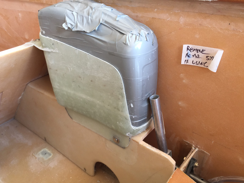
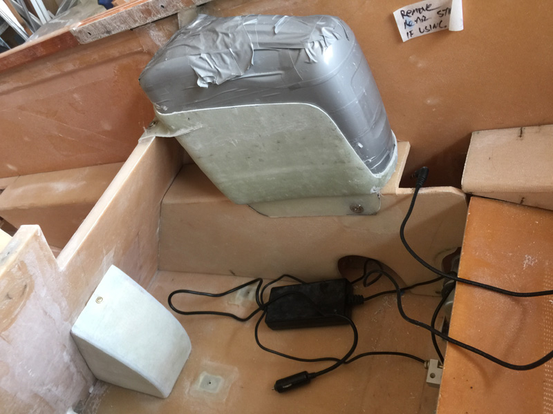
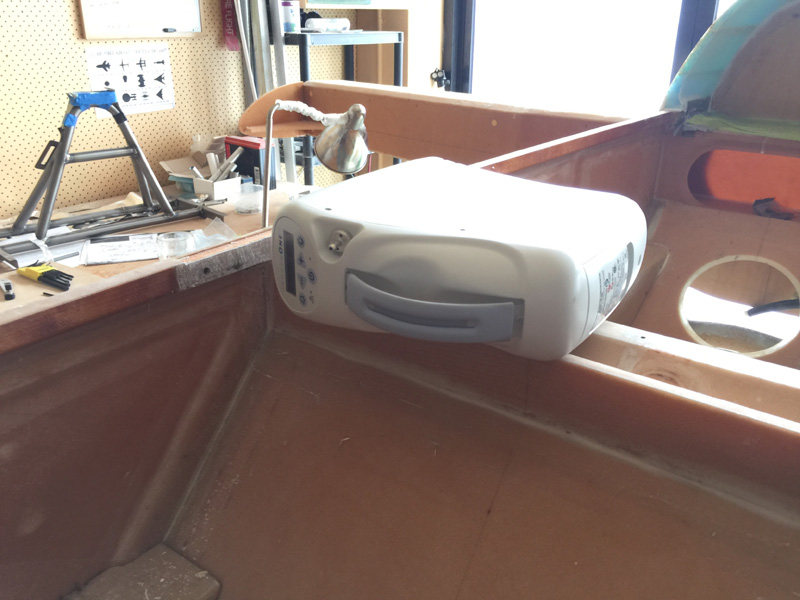
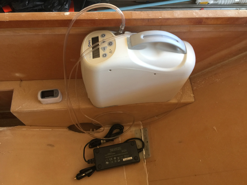
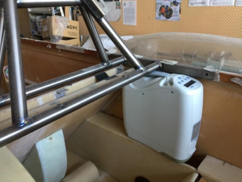
Back on January 20th, 2018 I chopped out a part of the front seat to fit the oxygen system and allow access. Now 22 months later I realise that it was a bit too much. The seat cushions will be hanging in mid air at the top. I could live with that but really, not quite right Dave! I had the idea of a bag for storage velcroed to the back of the seat. Wrong again. I’m better off with a shelf here and easier access.

OK so I’ll just put a bit of the seat back….back!

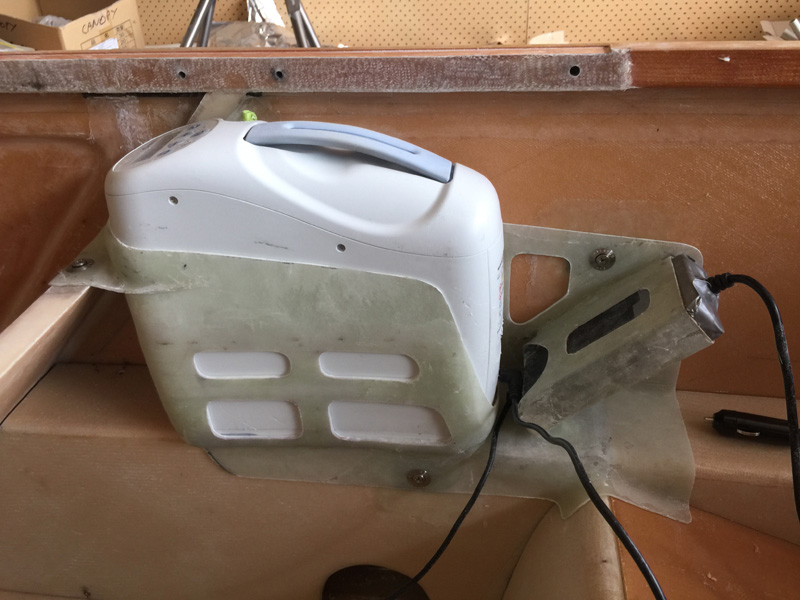
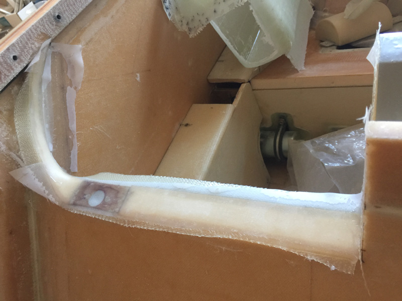
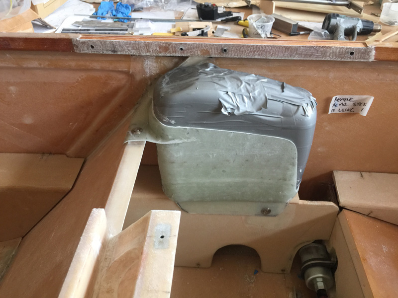
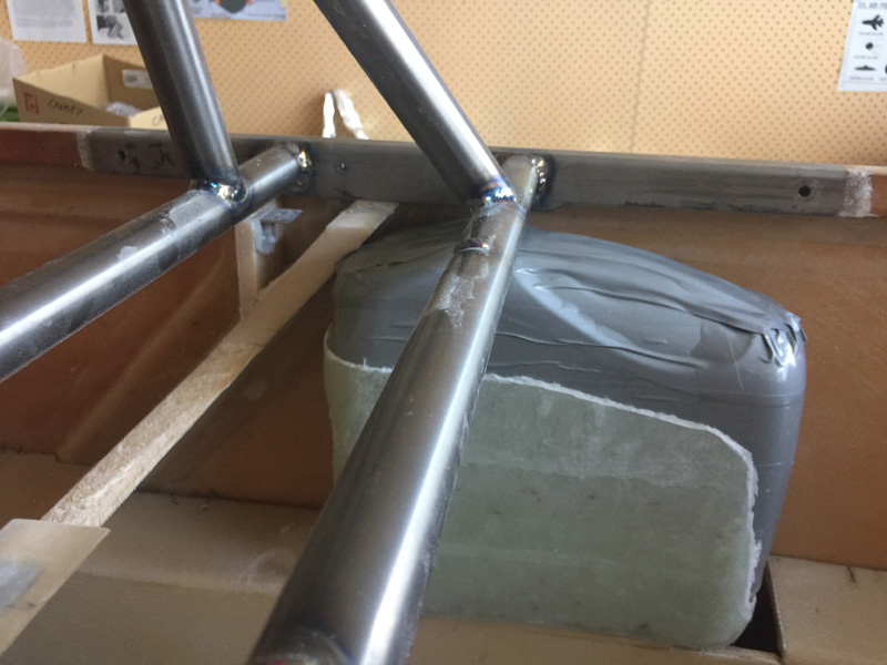
This is where I began.

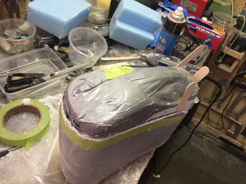
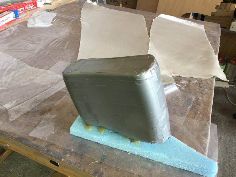
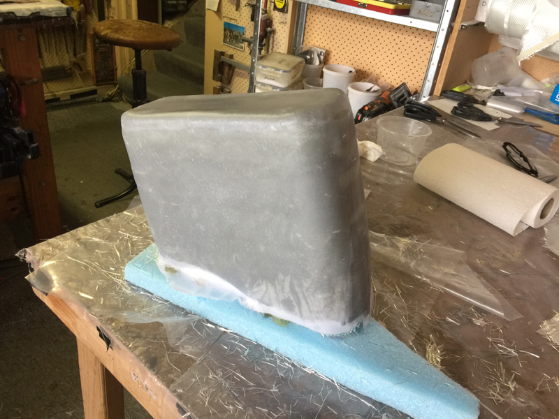
After checking the plans layups for the seat I went ahead and made an insert. Then for glassing the front I went with reinforcements via hot glue at the rear.

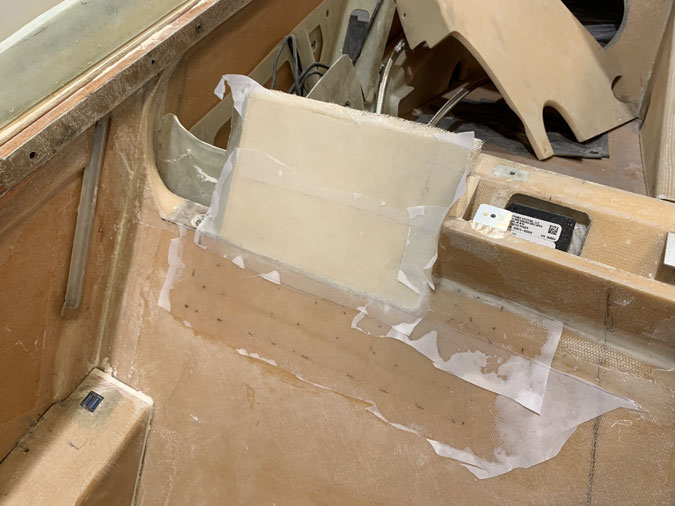
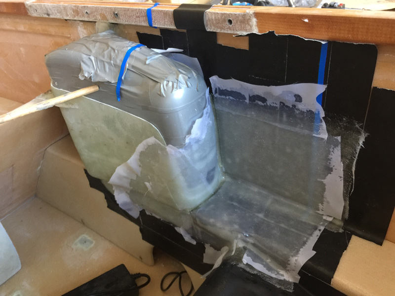
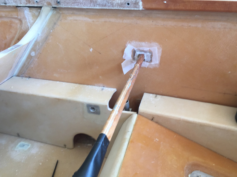
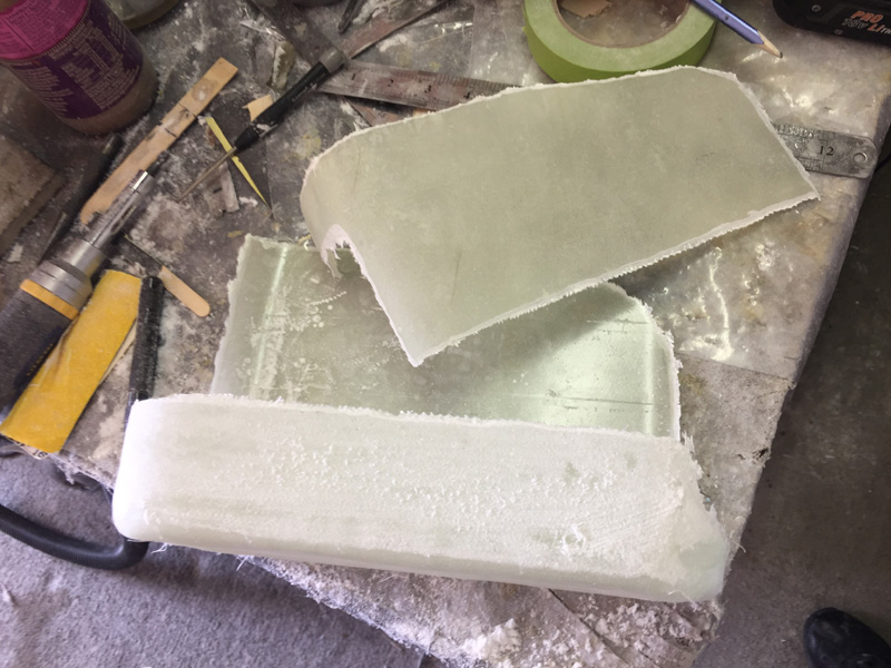
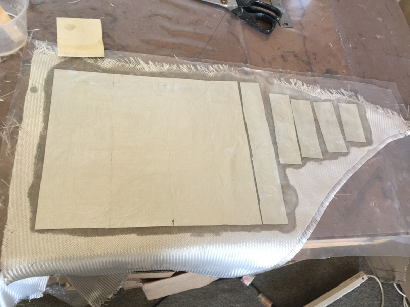
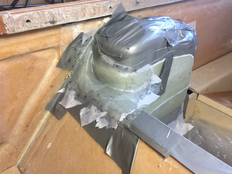
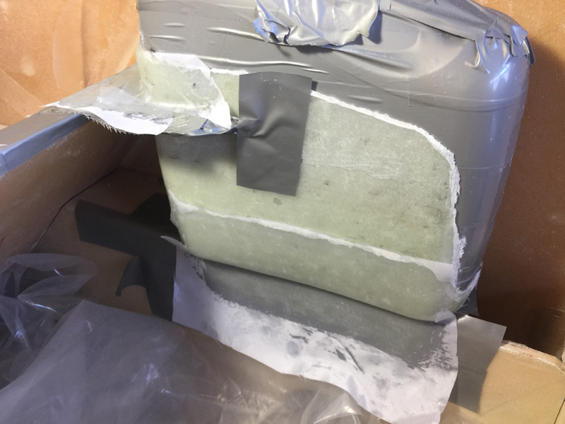
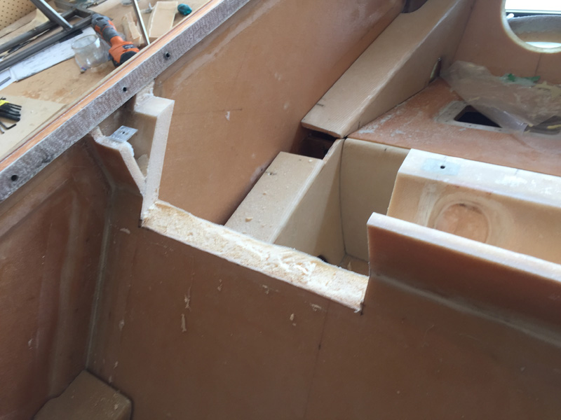
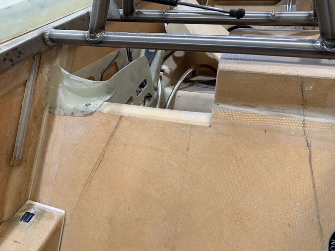
I did a ‘structural repair’. Fancy talk for removing 1″ per ply of the surrounding area and restoring the glass plus a ply of BID on top. The dotted lines were my guide to where the plies had to go. I did the usual layups on foil and plastic.

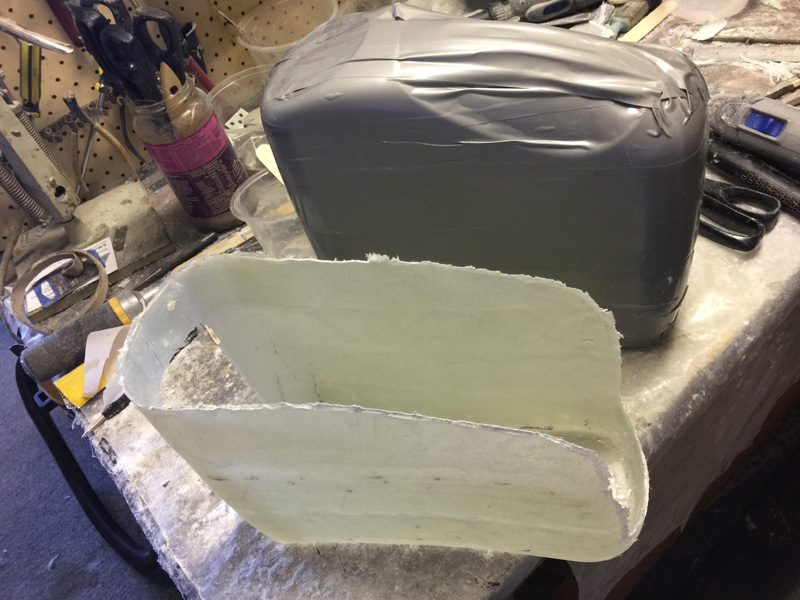
When that had cured I added the new front piece. Glass tape corners also went on the inside. When this all cured I added two ply of BID to the rear of the seat to tie in the new seat back, again with overlaps. Oh, and I had an air bubble in the glass that needed some epoxy injected into it and a clamp overnight. Worked a treat but more delays.

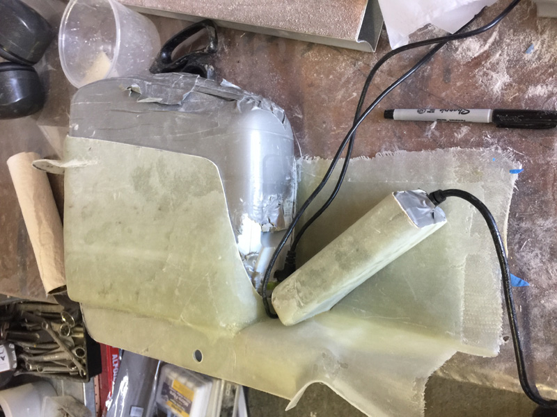
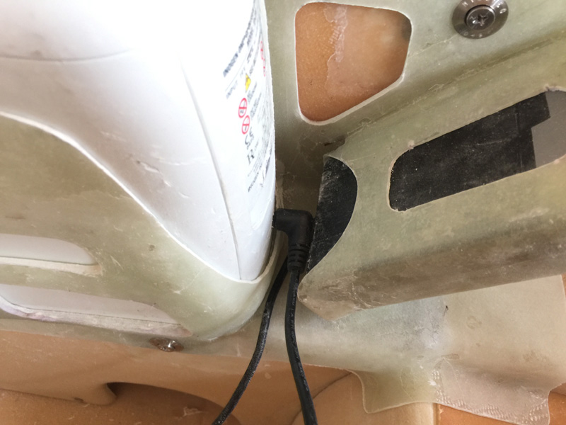
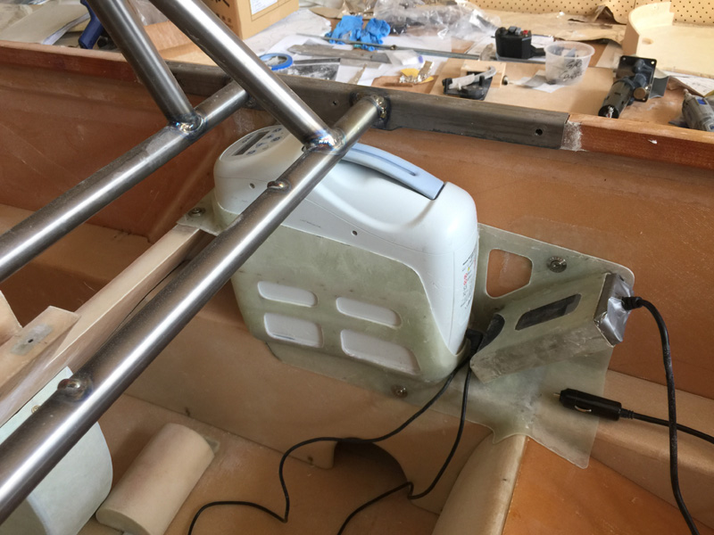
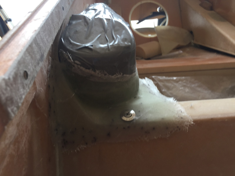
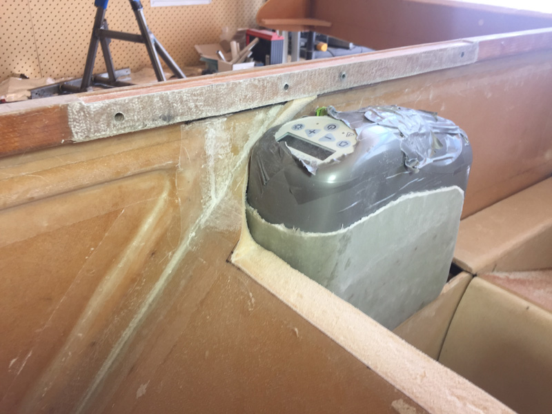
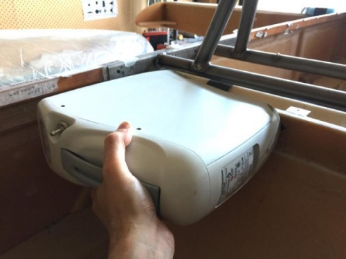
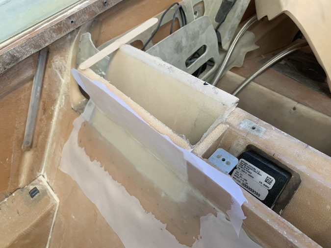
After all that I added the side end piece. This was after a few hours fitting and refitting the oxygen with the rollover in place to ensure I could get it in and out without disassembling anything! Quite important.

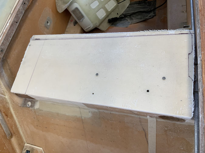
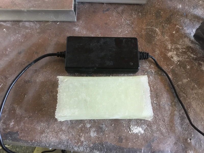
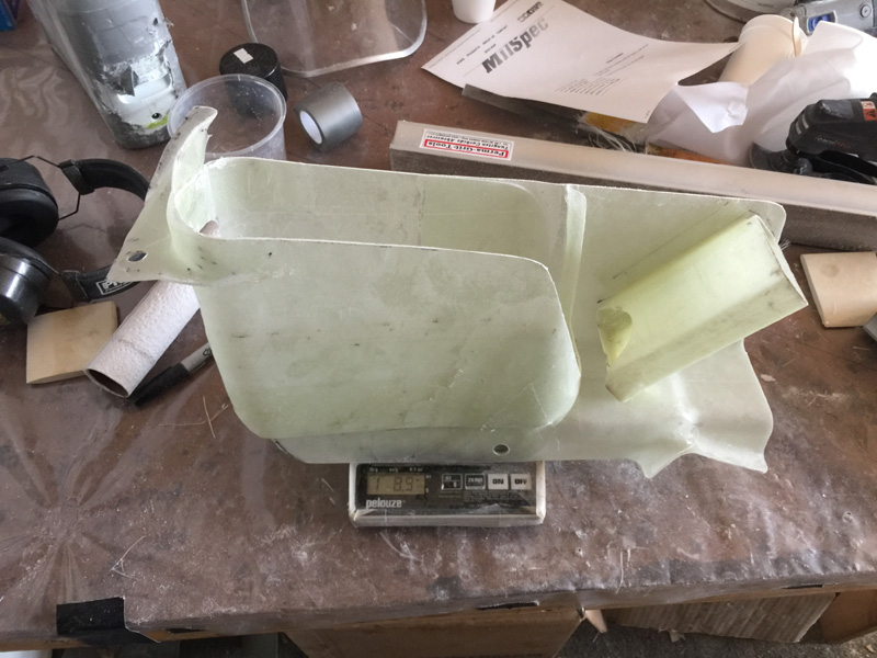
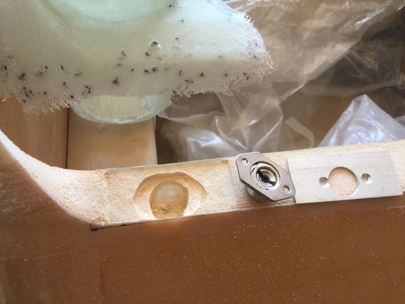
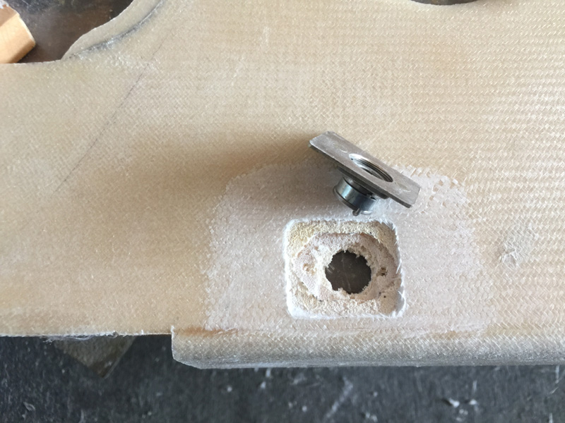
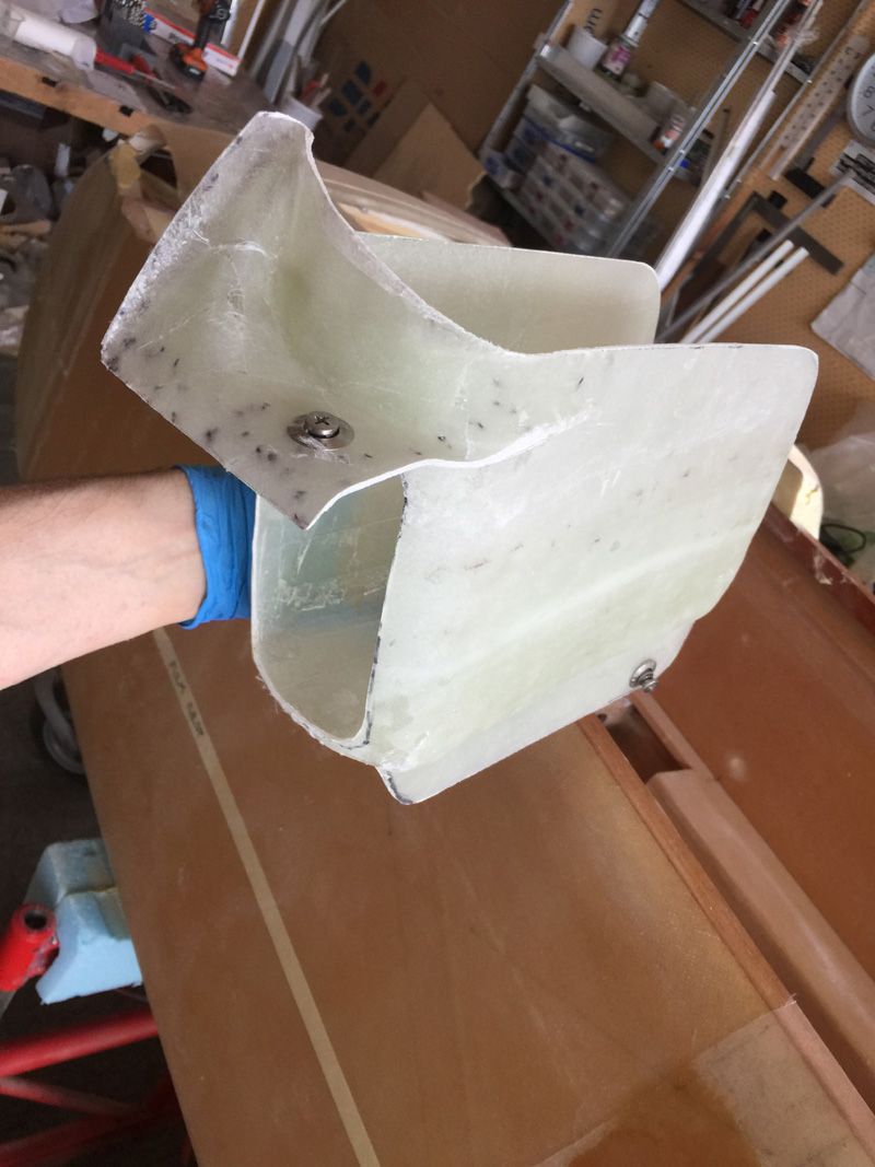
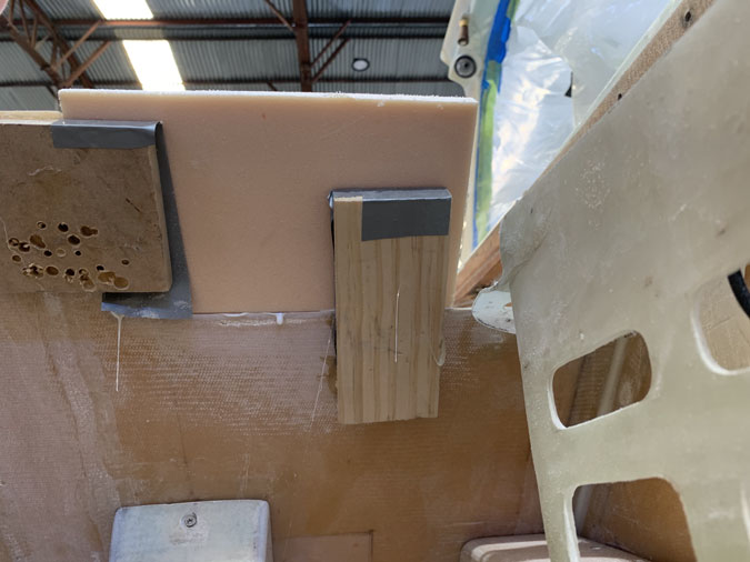
I made a shelf and glassed one ply of BID one side and two ply the other. Its the same foam as the instrument panel, given I’ll have an overhand I wanted the extra strength. I used some plastic to match the holes for the screws on the removable side of the shelf.

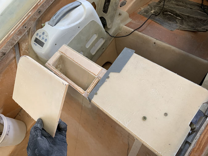
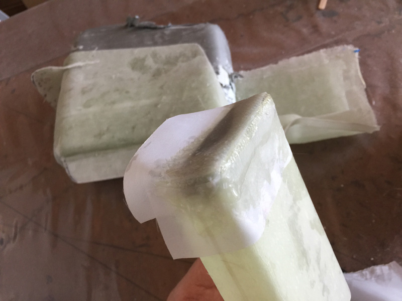
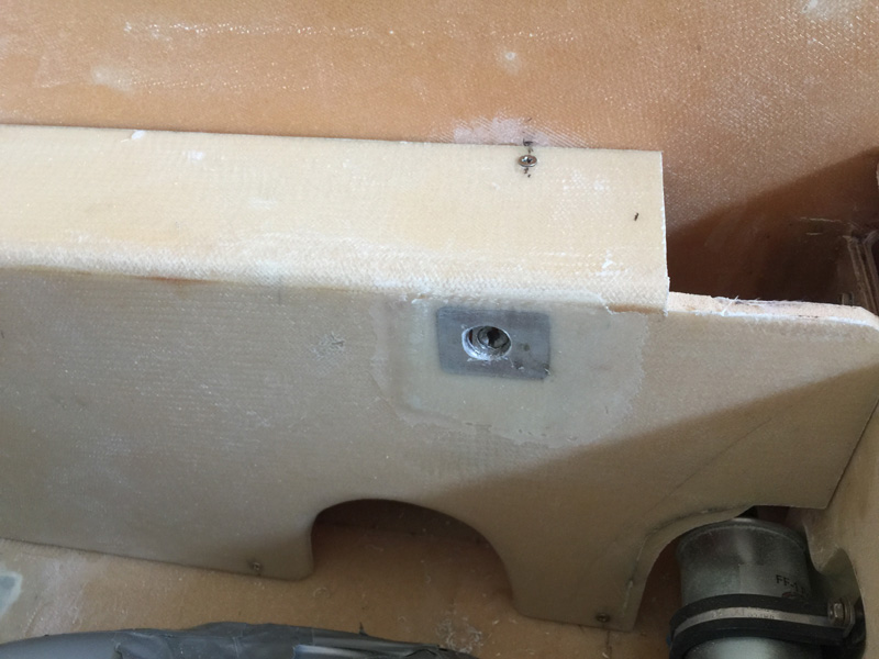
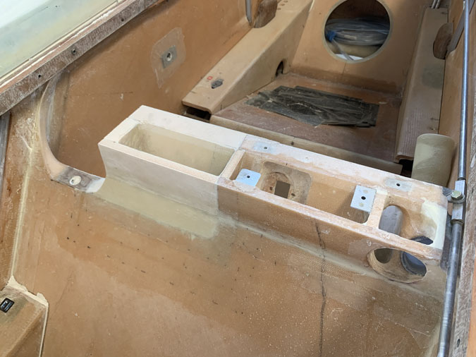
When I was happy I cut the top shelf almost in half. The reason is that I have the vent and the USB  block which needs access. My idea is to glass the rest of the top piece in place which will tie the seat back addition in place with a lot more strength than having the whole shelf removable. You might notice I have small troughs in the foam. These are for flox corners given I can’t do inside tapes when I put that piece on.

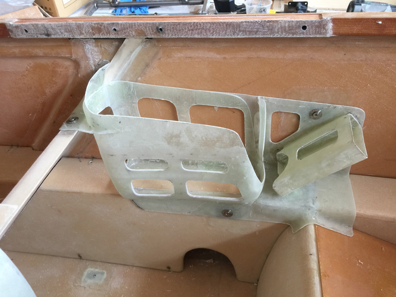
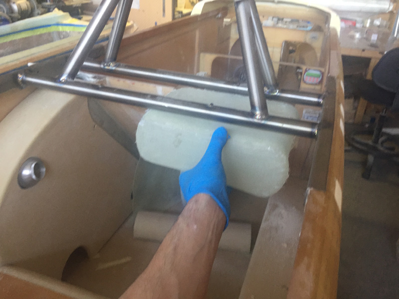
Here we are good as new. What I should have done in the first place and saved myself 20 hours plus extra work. Its in the past now and the job is done.

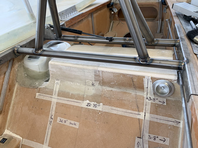
A final look with parts in place. Better eh? The tapes and measurements are for my seat cushions which will be made shortly.


Oxygen Install 4

Date:  01-29-2018
Number of Hours:  16
Manual Reference:  no ref

Over the last three days this oxygen thing got done.

First up was confirming that if the oxygen is installed I MUST have the back seat control stick removed. I also did a bit of work trimming the front and back armrests for freer stick movement. The final check will be with the wings on and everything hooked up. This is an essential check that is in my notes for that end stage of the build.

My idea is to make a cover over the rear stick a part of the oxygen install. So if the O2 is going in the plane you can only do this IF you remove the rear stick first. It’s ‘sort-of’ fool proof and I won’t need a placard or constant checking.

I mocked up what I’d need with some foil. I’m adding to what I’ve already done with a bit of an overlap.

Here’s the layup done with two wetted out pieces of 4 ply BID. I’ve allowed overlap on the rear seat and sump too for extra support.

Not pretty and it was again a bit of a struggle getting the Oxygen unit out of the form.

I’ve decided to now incorporate the voltage brick into the ‘Oxy holder’. Now I can see where it will fit and the decision to not leave the brick it permanently in the plane is made.

I had to cut the cured glass off the voltage brick with a thin cut down the middle that I quickly rejoined with a 2 Ply BID tape. Next up was squaring off the ends and making a proper end piece so I had an open ended box.

Here’s where I’m putting it. At the rear of the oxygen unit is where the air exhaust is so I needed to leave that uncovered, hence the angled brick. I first floxed it into that position with the brick in place. I’ll explain why the position is so important in a later picture. I’m sure you can wait for that.

With the brick holder now also taped in place on three sides, I trimmed the whole unit to be a little tidier. It turned out to be quite portly at 1lb 8.9 ozs and as solid as a rock.

While I needed to address the weight I also needed one more fastener. So the unit will be held with just three camlocs. It will be self contained too for easy install and removal. It only needs the 12 volt adapter plugged in. I had to again make an aluminium plate for the Camloc, drill it out, clean it up, alodyne it, rivet the receiver in place and then make a hole in the side for it after match drilling the position and finally floxing it in place. Add a few drops of sweat too. The stick is to hold it while the epoxy dried of course.

After cure I set up the third Camloc in the ‘holder’ and all was secure.

Here we are after some hours making the unit lighter. I got nearly a quarter of the weight off with these lightening holes and it is still very strong. You can now see the three Camlocs and how it also sits over the rear seat and of course covers the stick hole.

Here’s the holder with the hardware in place.  Yes I will shorten the wire from the brick to the Oxygen concentrator, probably around 3″ will be long enough. You might notice a “D” shaped cutaway at the bottom of the brick holder. This is so you can slide the unit up and unplug it from the main unit easily.

OK, here’s a clever bit (I say modestly) When the brick is in place, it also acts a a stop so that the power plug cannot come out. This took a bit of thinking and turned out to be very simple. I had a concern that being behind me in flight a simple plug might get dislodged in rough weather and I wouldn’t notice or be able to do anything about it. This design prevents that particular failure mode.

Here’s the unit with the rollover in place. It can only move upward about 1″ which would probably only happen in a crash anyway. The concentrator is pretty tightly held on all sides. While you can not remove it with the rollover there, it is easy to just loosen the Camlocs and uninstall the oxygen as a complete unit.

The position of the rollover and where the cannula attaches is such that the frame of the rollover will help keep the cannula tube plugged in. Another little design bonus.

All thats left is to work out the 12volt power. This was an interesting modification and solution to the whole oxygen issue in a small plane like the Long-EZ. I’ll be good to 18,000′ indefinitely, no bottles to refill. The ‘holder’ and position was not anything like I first thought it was going to be. A little magic happened and now I have a new storage area in that large cutout on the front seat to fill with a bag. Bonus!


Oxygen Install 3

Date:  01-26-2018
Number of Hours:  7
Manual Reference:  no ref

The last two days were just sorting out the two fasteners and a bit of glass on the top seat back edges.

It took me a little while to get my head around the Camloc fasteners. I bought these years ago when I was going to update my present Long-EZ cowls, before I even started building. I had to grind a little off the back of this one to get it fitting in the slopping seat back. I made a light aluminium plate, the plate got some alodyne, I added the rivets and used fast set epoxy to get it in place.

Next up I prepped that small cutout area for flox corners and did a two ply layup on the top. That took the afternoon.

Today I got the camloc working and all lined up.

I thought I’d just need two and put the second one in the armrest.

All done with the fast set West epoxy. That is strong enough for this sort of job. I allowed a little epoxy into the sliding area of the nut plate so that was an extra hour with dental bits getting it mobile again. The build can be unforgiving at times.

Here’s my trimmed oxygen holder, with fasteners. You really can make odd shaped things quite easily with fiberglass.

Here’s the unit fitted and locked. I need air circulating at the front and rear so while I’m tempted to use that triangular space at the front of the unit for the voltage converter,  I’d better not. There is slight movement when the whole unit is in place that I will have to address. The vibration of the plane in flight would over time fatigue something. I’m thinking about a removable holder that ensures the unit stays plugged in. This could double as my final fastener.

Meanwhile there are two more issues. I need to see how much rear stick movement might be restricted by the unit. I may have to placard for no rear stick when I have the O2 unit on board. The other thing is deciding if that brick in the picture above is staying or will it be removable? If it stays, I can hard-wire the ‘adapter’ end and have one less failure point where it would need to plug in. I could also permanently mount that brick. The downside is one pound of weight that stays in the plane even when the O2 is out.

Let me know now if you have any ideas! It is tomorrows job.


Oxygen Install 2

Date:  01-24-2018
Number of Hours:  12
Manual Reference:  no ref

Here we have the Oxygenator in its ‘case mold’ and guess who spent a full day trying to get it out? Part of my agenda was not to damage the hardware which certainly slowed the process as I nibbled away at the edges trying to see where it was stuck.

In the end I cut a great section out as you see below. That got it done…

Of course the next day I had to repair the cutout. This was a lot of extra glass and work.

Another day to cure and here we have what I wanted two days before, a perfect fit holder for the O2 system.

The next problem was after making that cutout I could see how it was going to fit. Not so good. It was taking up a lot of passenger space. Yes maybe you will come flying with me and you would not be happy.

Eureka! Now I’d made that huge cut in the seat I realised a new position for the Oxygen. It could go on the rear seat forward cover because I could access the Oxygen unit controls from the front now…due to the giant hole.

It did need a lot of trimming and shaping of the seat back corner for a good fit. I did a bit of hangar flying and it was easy to turn around for those controls. I’d call this a win.

You might notice in the above picture after a couple of hours after grinding and fitting the unit so it was sitting right against the seat back.

The next issue was how am I going to secure it, and have it removable? I decided on making a sort of fairing at the front which will get a camloc later. It may look a mess now but imagine all cleaned up, it’s really going to lock the unit in place.

The other place it will lock is on to the side cover, again with just one camloc. Oh and it turns out I’ve lost part of the camloc install tool so that was ordered today from the USA. I can still go ahead with things until it arrives.

After a cure and  trim I still have to sort out where the voltage step-down brick is going, like you get on laptop computers. This goes to the 12volt adapter. If I hard wire it I have one less plug but gain a pound in weight forever in the plane. Another issue is that I think this Oxygen unit will interfere with the rear stick movement so I’ll need to ensure that it is removed when the O2 is in place.

I am MUCH happier with this install position. The big hole I cut might get a leather bag with a zip later for general storage including the cannula. I’ll make it strong for now and work out what goes there later. I am thinking I might be leaving the Oxygen in the plane most of the time. I’ll look at the rear stick and perhaps a short one will not cause interference. We will see.


Oxygen Install 1

Date:  01-20-2018
Number of Hours:  6
Manual Reference:  no ref

I opened the unit up and found it quite unsuitable for remote operation or any chance of making it lighter and smaller, so it has to go in as a unit. Given its weight I can also remove it for local flying too if I didn’t disassemble it. The other thought was that given these concentrators should have an annual service and a check that they are correctly delivering the oxygen its better to keep it ‘original’ for transporting to the agents service center.

After much thought again I decided the best place to put the oxygen was ‘in’ the front seat and supported from behind. I have a few ideas for the leads and plugs too.


I was a bit unsure if there were structural issues here.  My own feeling was that I have the Titanum rollover now bracing the sides which might well take up the load and that I don’t have the usual strake cutouts there. I did get in touch with a very well respected structural engineer that will remain unnamed. While my eyeball engineering says this is OK, I did want some similar input using the same method but more experienced eyeballs.

“My primary thought here has to do with the torsional stiffness that the per-plans front seat bulkhead adds.  However, with the lack of strake cut-outs in the fuselage sides, my gut feel (NO analysis whatsoever) is that you are probably not compromising much with a cutout in the front seat bulkhead that you propose.  Myself, on my own airplane, I would make the outboard edge of such a cutout an inch or two inboard from the fuselage side, and “ring” the cutout with a few plies of BID, extending out a few inches beyond the edge of the cutout itself, and also lapping said BID an inch along the fuselage side.”

So with that in mind I chopped a big slot out of the front seat two inches out from the side.

Again a bit of thinking and I like the idea of the unit held tightly in a molded shelf. First up was the usual layers of duct/release tape. I added a bit of thickness here and there with removing the ‘mold’ in mind.

Here we are with 4 plies of BID and peel ply. The fun begins tomorrow after the resin cures getting the unit out of this mummified wrap. Then I have more ideas on how to fit it. This is one of the fun things on the build where you get to work out fittings without quite knowing how to do it until you start.


Oxygen System Test

Date:  01-17-2018
Number of Hours:  0
Manual Reference:  no ref

My idea is that when traveling the world, getting an oxygen bottle filled might be a real problem. What I want is oxygen supplied that I can use up to 18,000 feet that never needs refilling. No oxygen bottles! Some system that treats the air at those altitudes and gets it to a pressure that I can breath in and retain the same sort of ‘saturation’ in my body that I have at sea level.

To achieve this I’m going to use an Oxygen Concentrator. These are portable devices people use on the ground for supplemental oxygen as required for certain medical conditions. The units compress the ambient air and with come chemical magic deliver oxygen in a pulse method triggered by an intake of breath. This is similar to the pulse demand oxygen systems that normally go with an oxygen bottle.

Before I installed my Oxygen system I needed to test it in real world conditions. I bought an Inogen One G2 second hand and had it serviced and checked. It weights 7lbs and runs off its own battery (good for a couple of hours) or a 14v aircraft power system. It was originally designed for being used at home with 240volts but has an adapter for the car or when traveling on a passenger plane.

Here’s the unit and just on the right is a fingertip pulse oximeter. I had this calibrated at a hospital and I received some instruction on when readings were reliable.  The usual power brick is on the floor and a cannula is shown plugged in. For the test I just used battery power.

I flew with the generosity of a pilot (Dave) with a very nice Mooney. His updated panel was really impressive and convinced me to go for the expensive GTN750 if I both afford and fit it in my panel. The previous plan was the smaller GTN650 which Dave also has.

Dave filed an IFR plan and after take off we headed south and climbed straight up to FL180. That 18,000′ and the limit allowed for a cannula system. Higher than that a full flow mask is mandated.

My plan was that he would be on his plane’s usual oxygen system the whole time and there would be oxygen available for me if my system didn’t work. I’d know this by continuous checking with the finger oximeter. As I was the passenger, he did all the flying and I considered this a good safe method to test my system.

Below are my simple test results. I was at 98% on the ground as we taxied out. At 10,500′ you can see quite a low reading of 82%. I took a few extra breaths and it went right up again. I was learning that I need to concentrate on normal good breaths, not those of a lazy passenger taking in the view and super relaxed. Oh yes and thats my usual handwriting, not those of an O2 deprived person. Too much keyboard work perhaps.

We went into a holding pattern at 18,000 feet for over 15 minutes and I found that while there was one low reading of 94% a few extra breaths and I was back up to 97% which was very easy to maintain there after with normal breathing. I should have been more excited, the system WORKS! It’s going in my plane.


Oxygen System Position

Date:  10-09-2017
Number of Hours:  1
Manual Reference:  no ref

Here we have my proposed, self contained, no bottle, Oxygen system.

Its an Inogen One G2 HF (high flow). I’ve done all the research I can and I hope this is going to work. The down side is its weight, 7.5 lbs with the bigger battery and the 1lb 12v adaptor.

Size is 9.5″ tall, 3.9″ wide and 10.7″ deep. A version of this unit is certified to 18,000′ with a cannula. That’s the maximum height with cannula anyway. I suspect from a lot of research that the certified one is a re-branded exact same version as this one. I’m 90% sure.

I am arranging a flight where I’m a passenger in an unpressurised plane to test my unit out. I want to be ‘not flying’ or not the PIC and have standby oxygen on board for me. I have a finger oxygen meter which shows I have 98% to 99% O2 in me on the ground. I’ve also bought a peak flow meter so I have a base line for my lung capacity to ensure I’m AOK on the day of the flight.

I’m still trying to organise this. I shall report back to you! Meanwhile I’m only thinking of how and where to install this unit for my world trips. With no O2 bottles to get filled, traveling life would be easier. The unit can be powered from the plane’s 14volt power and it has its own 4 hour backup battery that fits on the bottom of the unit (as pictured).

Not here?

No room here!

Might work here with a cut?

CategoryLogsHours
All157617079
Uncategorized135
Ch 3 Education220
Ch 4 Fuselage Bulkheads25231
Ch 5 Fuselage Sides32283
Ch 6 Fuselage Assembly30270
Ch 7 Fuselage Exterior14140
Ch 8 Roll Over/Seat Belts990
Ch 9 Main Gear/Landing Brake71642
Ch 10 Canard28287
Ch 11 Elevators36298
Ch 12 Canard Installation12102
Ch 13 Nose and Nose Gear1291097
Ch 14 CenterSection Spar57525
Ch 15 Firewall and Accessories448
Ch 16 Control System27237
Ch 17 Roll/Pitch Trim System654
Ch 18 Canopy70502
Ch 19 Wings, Alierons1271090
Ch 20 Winglets/Rudders71528
Ch 21 Strakes - Fuel/Baggage65437
Ch 22 Electrical System591031
Ch 23 Engine Installation961152
Ch 24 Covers/Fairings/Consoles25202
Ch 25 Finishing561084
Ch 26 Upholstry340
Fuel System46310
Rollover1050
Cabin heating System60331
The Ferry Tank335
Blog2694182
Build Mods2252513
Nose Gear Doors856
Wheel Pants/Gear Leg Fairing40473
Oxygen System762
Roll and Pitch Trim964
Winglet Intersection Fairings445
Baggage Pods11104
Pilot Side Windows437
RAM Air & Hellhole Cover15177
Main Gear Beef Up322
Post Cure124
Fire Extinguisher16
Wing Fences13
EVS (Enhanced Visual System)130
Hinge Upgrade115
Cowl Keeper110
Rudder Gust Locks19
Cooling20607
Taxi Tests42
Flying10

Complete the Test Flight Program

2025/6/30 10:26:01

Round Australia in Four Flights

2026/4/1 10:26:01

Round the World Departure

2026/8/22 10:26:01

Rough River Flyin, Sept 23, 2026

2026/9/23 10:26:01

© Copyright 2025 Dave Berenholtz