• Home
  • Flying
    • First Flight
  • Build by Chapter
    • Ch 3 Education
    • Ch 4 Fuselage Bulkheads
    • Ch 5 Fuselage Sides
    • Ch 6 Fuselage Assembly
    • Ch 7 Fuselage Exterior
    • Ch 8 Roll Over/Seat Belts
    • Ch 9 Main Gear/Landing Brake
    • Ch 10 Canard
    • Ch 11 Elevators
    • Ch 12 Canard Installation
    • Ch 13 Nose and Nose Gear
    • Ch 14 CenterSection Spar
    • Ch 15 Firewall and Accessories
    • Ch 16 Control System
    • Ch 17 Roll/Pitch Trim System
    • Ch 18 Canopy
    • Ch 19 Wings, Alierons
    • Ch 20 Winglets/Rudders
    • Ch 21 Strakes – Fuel/Baggage
    • Ch 22 Electrical System
    • Ch 23 Engine Installation
    • Ch 24 Covers/Consoles
    • Ch 25 Finishing
    • Ch 26 Upholstry
  • Build Mods
    • Liquid Cooling, Numbers, Weights and Flow
    • Cooling
      • Solving Ground Cooling 1
      • Solving Ground Cooling 2
      • Solving Ground Cooling 3
      • Solving Ground Cooling 4
      • Solving Ground Cooling 5
      • Solving Ground Cooling 6
      • Solving Ground Cooling7 – Test Data
      • Solving Ground Cooling 8 – Flap Building
      • Solving Ground Cooling 9 – Hinges
      • Solving Ground Cooling 10 – Lower Flaps
      • Solving Ground Cooling 11 – Upper Flaps
      • Solving Ground Cooling 12 – Completed
      • Cooling the Beast 1
      • Cooling the Beast 2 – Lower Cowl Expansion
      • Cooling the Beast 3 – KW Oil Cooler Diffuser
    • EVS (Enhanced Vision System)
    • Cowl Keeper
    • Rudder Gust Locks
    • Wing Fences
    • Post Cure
    • Hinge Upgrade
    • RAM Air & Hellhole Cover
    • Main Gear Beef Up
    • Pilot Side Windows
    • Baggage Pods
    • Winglet Intersection Fairings
    • Titanium Rollover
    • Nose Gear Doors
    • Wheel Pants/Gear Leg Fairing
    • Cabin heating System
    • Fuel System
    • Roll and Pitch Trim
    • Oxygen System
    • The Ferry Tank
    • Cruise Angle Indicator
    • Fire Extinguisher Install
  • Round the World
    • RTW Route East #12 rev1
    • Survival Equipment
    • Training Flights
  • Other Stuff
    • Blog
    • Around the World: RAAUS Sport Pilot Issue 110
    • Taxi Tests
    • Summary Feb ’24 from an SAAA Meeting
    • AOPA Pilot 27th Sept 2019
    • Build Tests
    • Flying Stories
      • A Long Easy Dream ’06
      • Townsville ’07
      • Cairns ’08
      • Albany ’08
      • East Coast ’08
      • Brisbane ’09
      • Cairns ’10
      • Perth ’10
    • Non Build Mods
      • F16 Scoop for JZE
      • Ram Air Box for JZE
      • Strange Tips
    • Milestones
    • Links
  • Contact

Nose Gear Doors

Home
Build Mods
Nose Gear Doors

Nose Gear Door Guides

Date:  05-31-2018
Number of Hours:  8
Manual Reference:  no ref

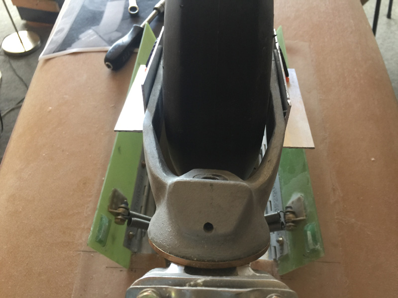
One issue with the nose gear, particularly if you have doors, is the possibility of the wheel being cocked to one side when you retract it. If you have the manual gear you just won’t be able to get it fully retracted and will have to fly around with a bit of wheel sticking out in the airflow. No biggie. This has happened to me several times on my current Long-EZ, JZE.

IF you have electric gear with a powerful linear actuator, its a different story. If the wheel is cocked you are going to break your gear doors on one side and possibly damage the fuselage floor or even worse.

Usually if you take off smoothly the gear which has some friction on it will stay straight and all will be good. IF you hit a pot hole just as you rotate you might have a problem. If you are on a very rough strip and you bounce the gear trying to get it up early to protect the prop, well thats another possibility of a cocked wheel and serious airframe damage.

OK, it is unlikely but the penalty is high if it does happen so I wanted to make ‘provisions’.

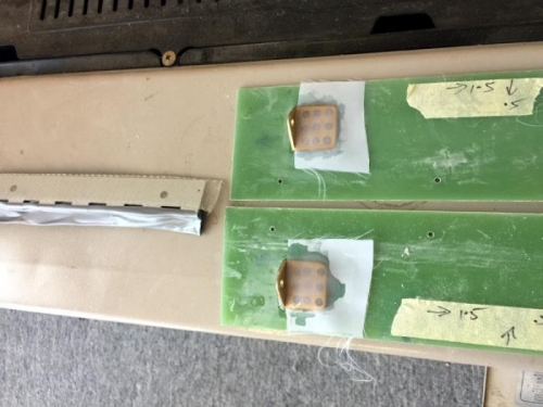
I got this design idea form ‘Waiters’ Long-EZ site. I made something similar out of cardboard and it seemed like a good place to start.

I tested it at different angles and found the optimum.

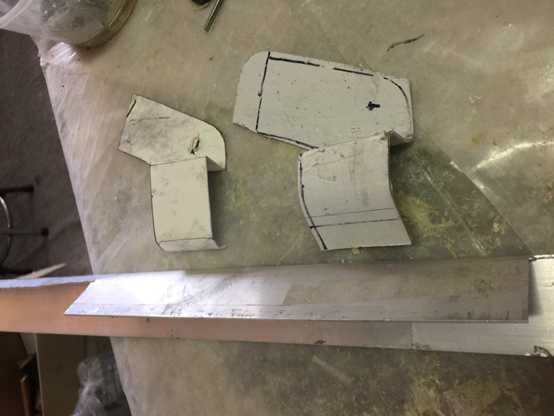
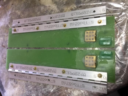
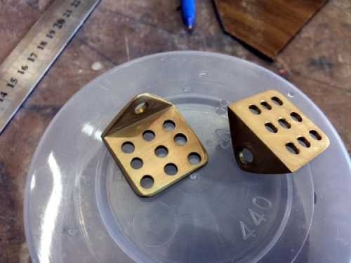
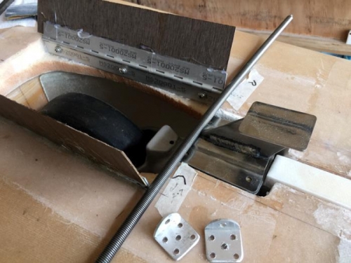
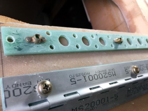
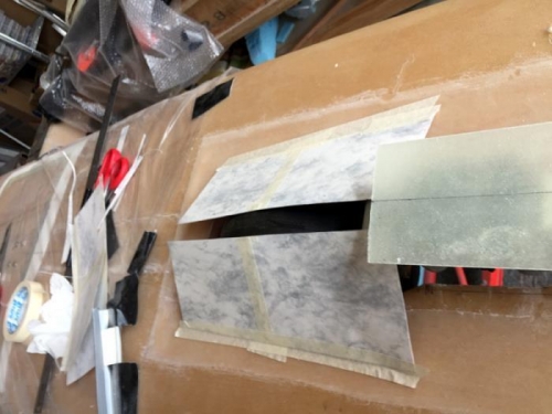
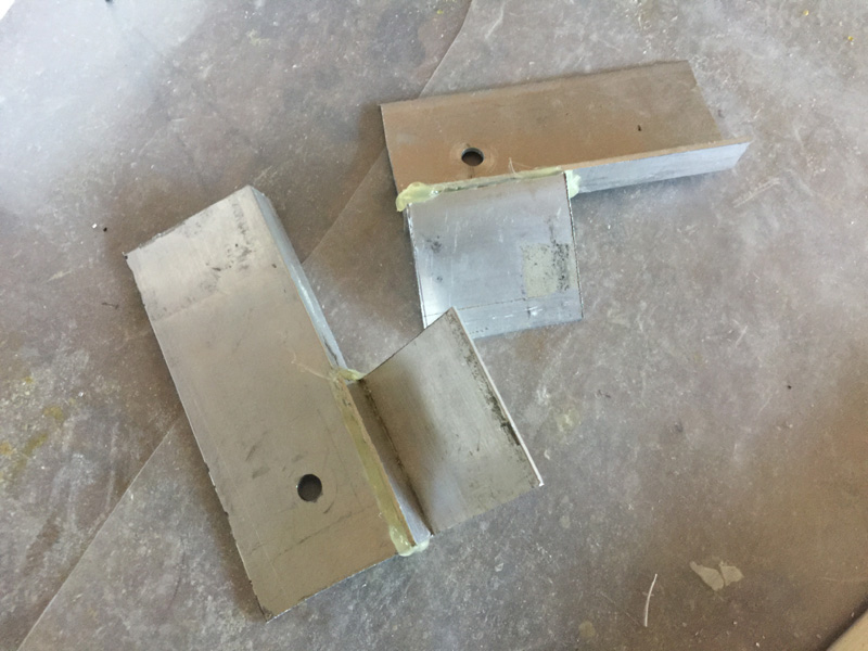
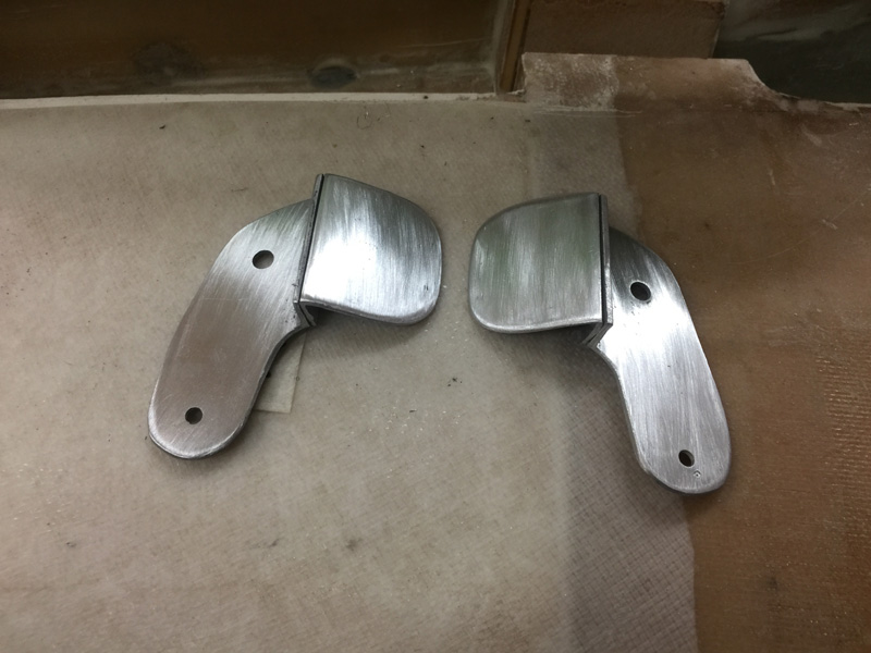
Ha! Now I spent a bit of time trying to bend that shape in metal. That’s the blob on the right of the pic. I’d call it an epic fail. Either I come up with another idea or find an RV builder to help.

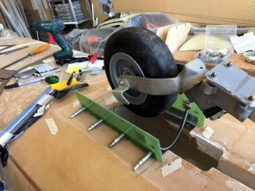
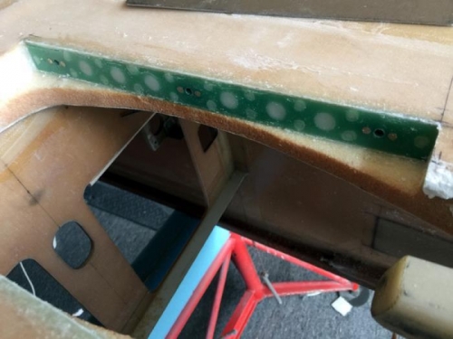
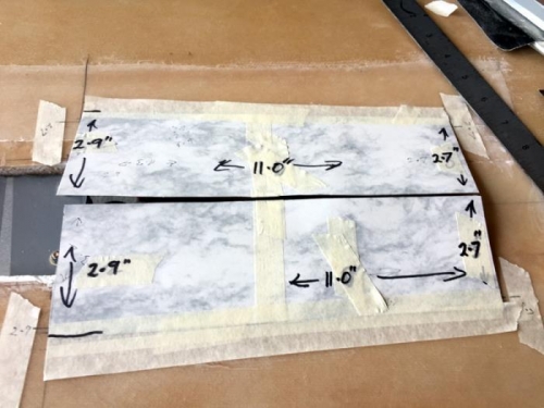
My idea was to get some aluminium angle and bend it a bit more again in a vice. That’s the bottom bit in the pic. The top piece is similar angle aluminium and its looking a lot more like my cardboard model without the bad bends.

These are clearly too wide here to fit in the nose cavity but we are on our way.

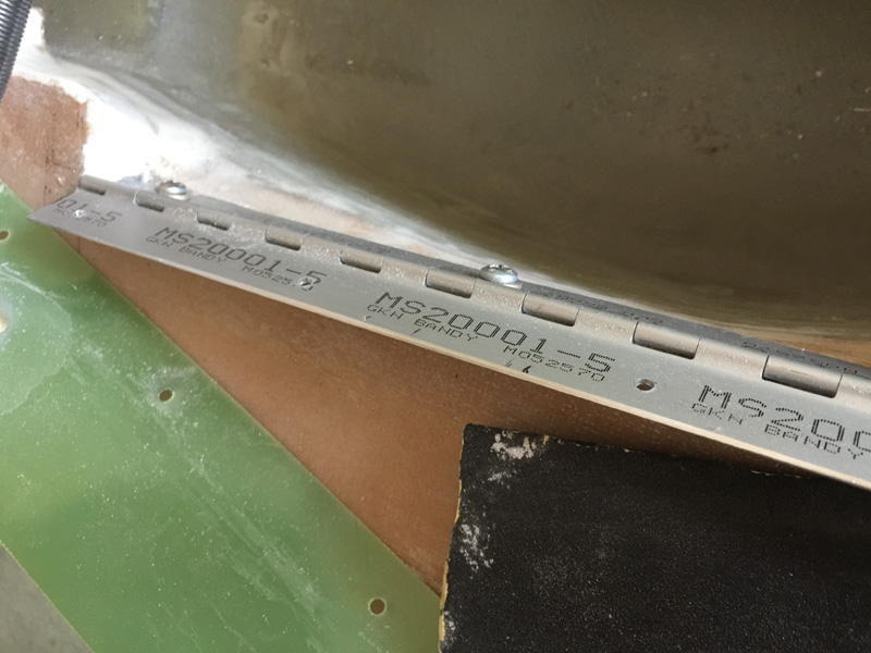
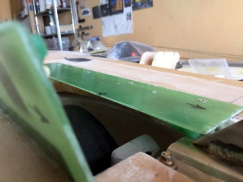
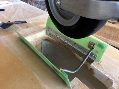
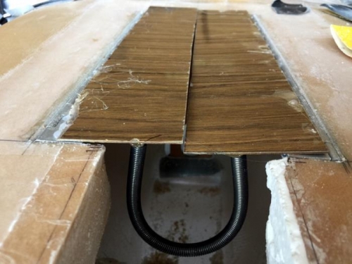
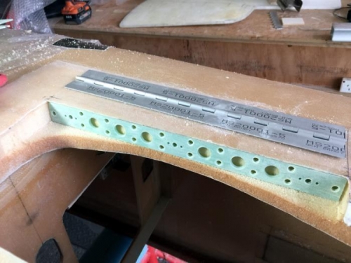
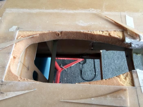
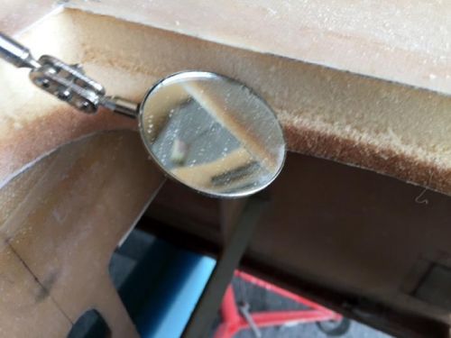
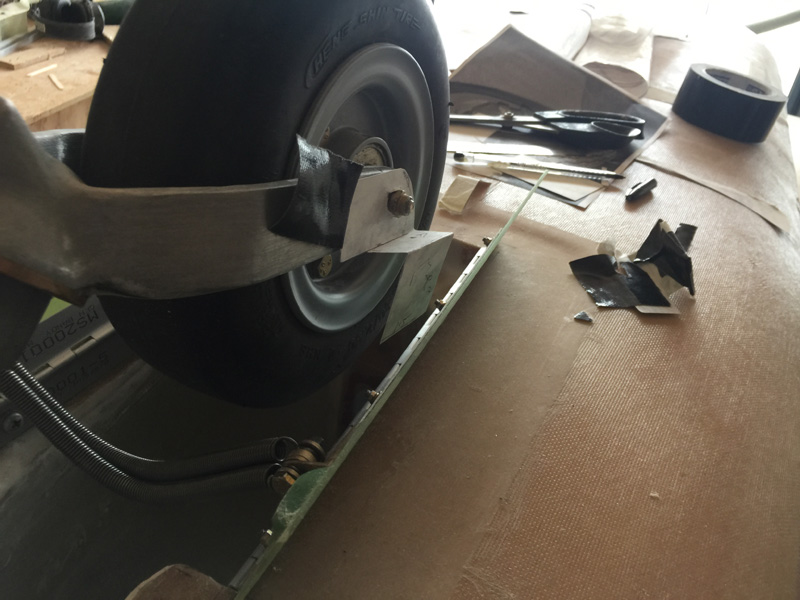
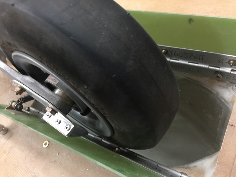
While testing the gear up and down I noticed that the wheel could get stuck on the very thin ledge that is the hinge! That was a surprise as the wheel could really get stuck here and break the doors! I was too quick, this time, to let that happen but here was another hidden issue. You can see the doors off in the pic and I then filed those edges into a nice very smooth curve which fixed the problem.

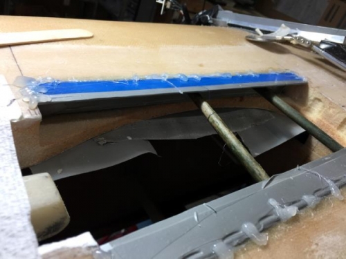
More testing, this time I hot glued some pieces together and again did the up down wheel thing. Yep it’s going well.

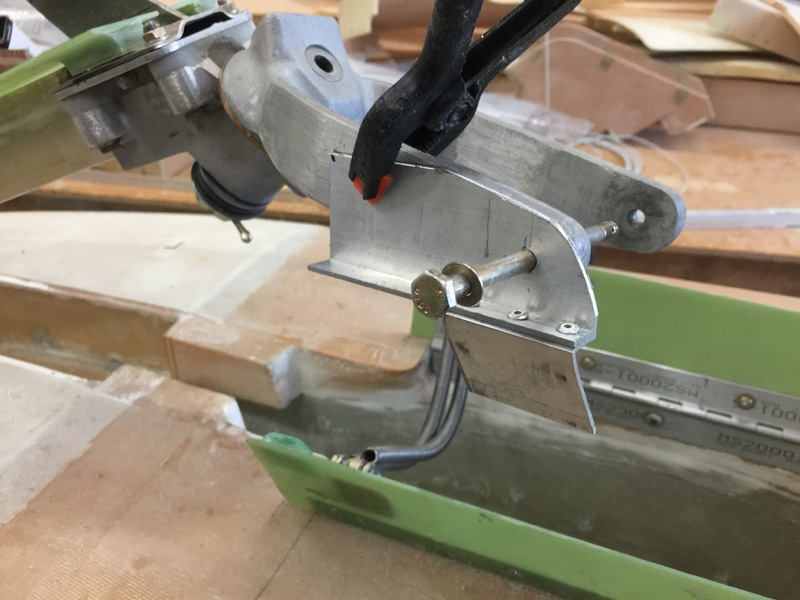
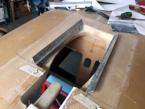
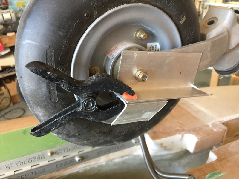
Confident in the design I used three cherry rivets to secure the two pieces. Then more testing to get the angles right.

When I was happy, some rounding and smoothing for my pieces.


Pretty….

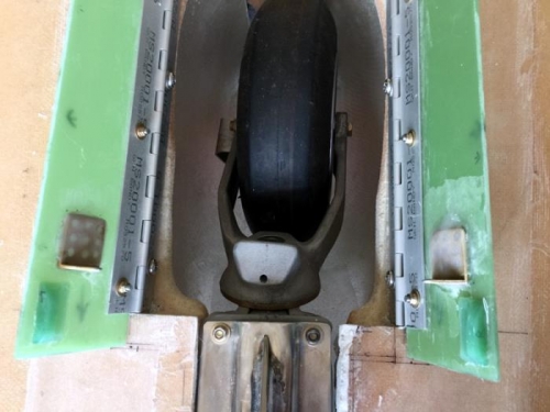
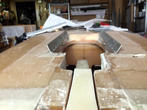
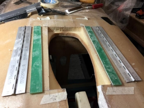
It is hard to see but we are a good width now.

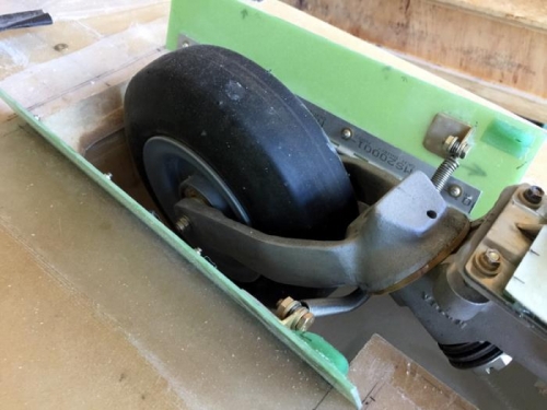
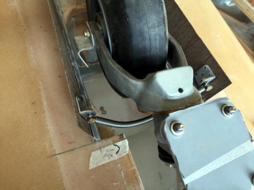
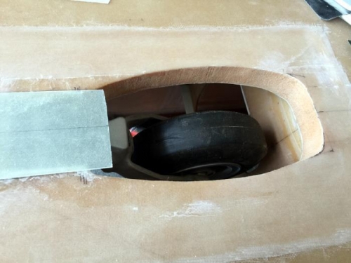
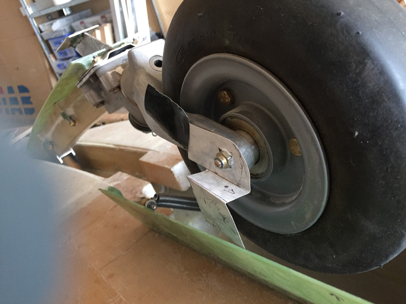
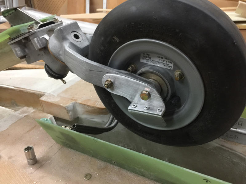
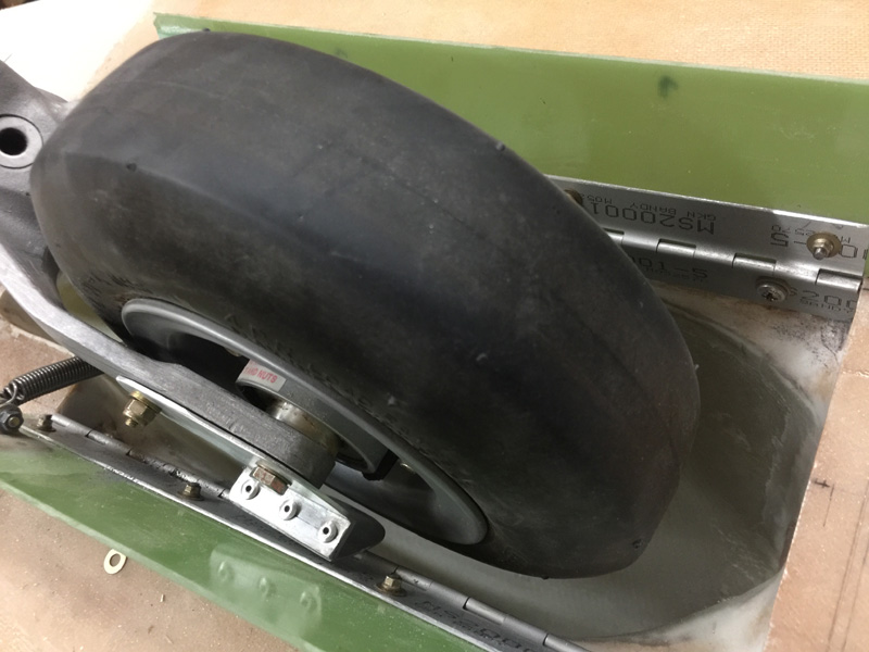
Can you see here that the tire is going to hit that tiny nut on the gear doors? Well another potential problem. I later moved that screw and nut 1″ rearward and filled up the old hole. Now the tire happily hits the open door, slides down that until it gets to the straightener, which then does the business of getting the wheel in the middle.

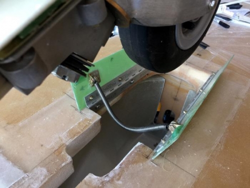
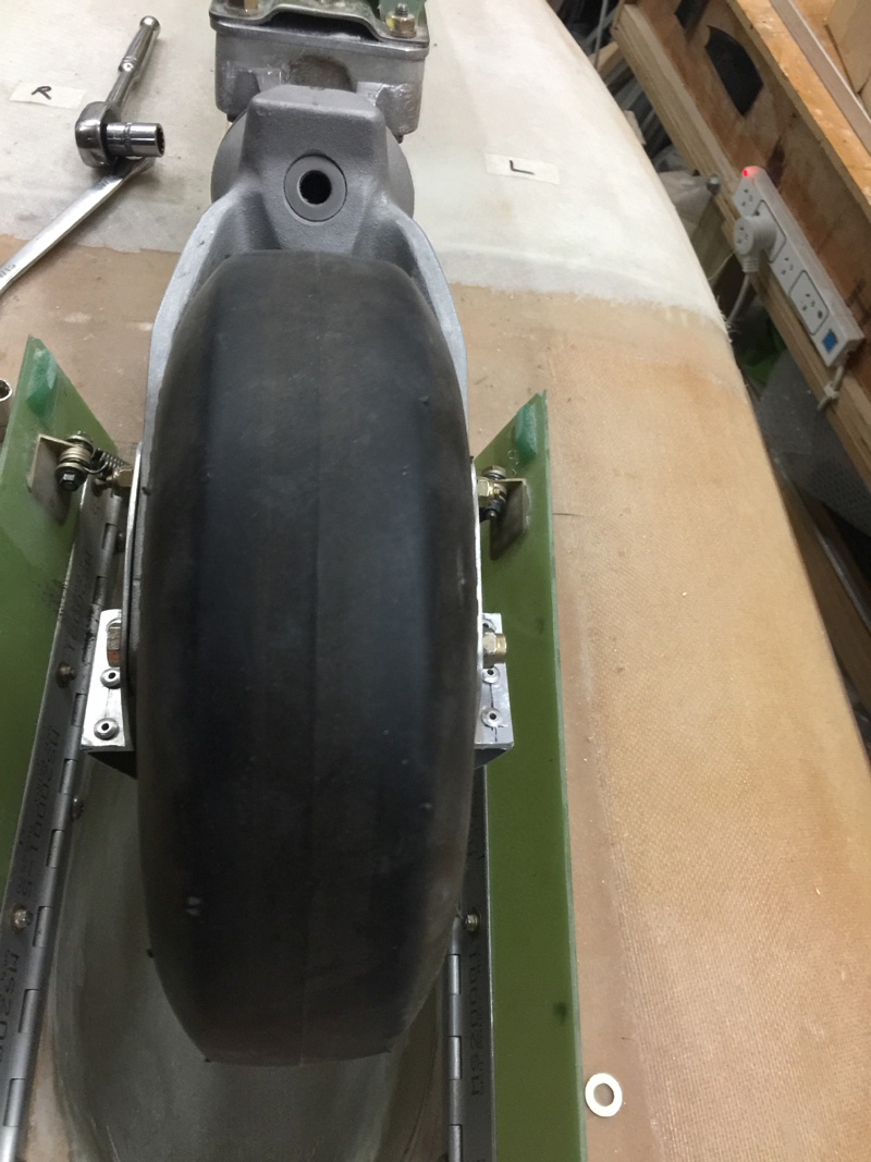
You can see here the straightener just contacting the gear door and then hinge (note the curve edge) to finally fit in the wheel well pretty close to straight. I’d call this one…. done.

Yes I will say that if the wheel is cocked beyond the edge of the doors it is going to foul up and all the work I’ve done here will not protect the doors. This is where a low value fuse comes in to at least stop the floor being damaged by the wheel. Frankly if the wheel is cocked this far to the side some other bad things have already happened. This little mod above mitigates most reasonable situations that could be found in normal ops.


Nose Gear Doors Fitted

Date:  10-30-2016
Number of Hours:  10
Manual Reference:  no ref

Many hours over several days went into all this and I’ll save you the drama. These next logs are out of order too time wise. I was doing a few things simultaneously.

Pic one shows that I’ve got the hinges on which are countersunk screws and locknuts. The idea is to have everything removable in case I mess up.

You can also see I’ve floxed on some door stops that come to rest on the gear leg propping plate, as you can see in pic 2. I wanted these at the outer edges for stability and being more of the Garolite G10 I can just sand them down to make the final fit perfect. As it is they close nicely.

Pic 3 is the wheel up so you can see the fit. I still have plenty to do in the wheel well but we do have working doors now.

Spring mounts and door stops

Front stops in action

Wheel up

Just three more pics here as I have a nice working set of gear doors to show off. They work very well and I’m quite pleased so far.

The spring is from Aircraft Spruce and you get them in 30″ lengths Part #01-37500 Tension spring OK? Just in case you need one. They are for the manual trim on a Long-EZ but perfect for this job too.

Wheel coming down

Down…down

Capturing the door spring

Nose Gear Doors, Real Ones

Date:  10-24-2016
Number of Hours:  6
Manual Reference:  no ref

Finally the real doors. These are made of 2mm G10. They are pretty stiff but I can always add a foam core if necessary. I’ve made them slightly longer than the hole they cover. The idea is that the bottom of the fuselage can be the door stops. I can adjust this height with a bit of micro and get them closing together and in line. I did do a joggle in this area when I glassed the fuselage. Frankly a total waste of time and it might end up with the same or more filler than leaving it flush. Oh well.

Pic 1 has me with a set of working doors. Needless to say I’ve had to recharge my 12 volt battery that runs the nose lift a few times with all the testing and checking.

Pic 2 shows that I have tweaked the hard points, added holes for those flox ‘fingers’ and alodined the parts mainly to help the flox adhere.

Pic 3 Has me floxing on the spring holders. I also had to add two ply of BID to one hinge. I was SUPER careful drilling the holes for the doors in place so they would close perfectly. I must have spent 90mts fiddling with the hot glue and placement until I was happy. They still came out with a slight gap of about 0.025″ Its a good thing this is a plastic plane. The BID will push the hinge out nicely for perfect closure.

Real doors

Spring hardpoints

Spring points floxed

Nose Gear Door Mockup Test

Date:  10-20-2016
Number of Hours:  10
Manual Reference:  

Now the hinges are on I made a couple of test doors out of laminex. A step up from the cardboard ones eh? Pic 1 shows the plan. I’m using the same spring specified for the plans manual trim system on the Long-EZ. I’d bought it a while ago but I’m going electric trim instead. I did buy some mouse traps and pulled out the springs for a few ideas I had. This is experimental aviation after all.

I also had some brackets left over from making the nose lift cover. I grabbed the hot glue gun and started to try things. Pic 2 is what works… and works well.

I tried the piano wire hoop to hold the doors open but it turns out that this heavy trim spring does it beautifully, no piano wire (or mouse traps) required. Another thing is that unlike other builders who have attached the spring to some spare hinge placed lower on the doors, I’ve moved that point up a bit closer to the opening. I also wanted the spring removable for maintenance and tweaking the tension as required.

Pic 3 shows how the spring hangs with out the gear. Just a fraction shorter than this loop is nearly perfect in terms of tension.

Oh yeah, see on pic 2 something hanging off the wheel bolt? I’m playing with ‘auto wheel straighteners’ This is just a test. Someone smarter than me thought of it. I have a concern that the wheel can be cocked, particularly bouncing on a rough grass strip on take off and can then end up cocked to one side. (ask me how I know about this) That would smash gear doors when it retracts, so I’m looking to these ‘straighteners’.

Test pieces

It works!

Spring loop placement


Nose Gear Door Hardpoint Pics

Date:  10-19-2016
Number of Hours:  0
Manual Reference:  no ref

Pic 1 shows one hardpoint in place. This is amazingly strong, next time thinner G10. It also doesn’t need a ply of BID over it which some people do, a waste of time and weight in this configuration. That thing is not coming out without a fight.

With Pics 2 and 3 I’m trying to show the hinges slightly wider at the front than rear. You may just have to trust me, its only .2″ per door wider at the front.

So far so good.

Hardpoint in place

Hinge opening

Hinge opening front view

Nose Gear Door Hardpoints 2

Date:  10-18-2016
Number of Hours:  8
Manual Reference:  no ref

Having fitted the hardpoints I fitted three nut plates to each piece and match drilled them into the hinges. That stuff always takes a while with nice little countersunk rivets and neat holes. The G10 is so hard that it is no problem using hard rivets rather than the soft type to hold them. I also drilled many lightening holes which will also work for ‘glue fingers’.

While these hardpoints are only being glued to relatively soft foam, its over a reasonable area. I got the shine off the G10 for the epoxy bond and have to say they looked great…and no one but us will ever see them.

Pic 2 shows we are ready to go and pic 3 is the pieces floxed in place. I hot glued the hinges to the sides to hold them, made sure those screws were not going to be covered in glue and used a couple of bits of bamboo just to be sure the hardpoints didn’t bow out of position.

Trial hard point fit

Hardware

Hardware floxed in place

Nose Gear Door Hardpoints 1

Date:  10-17-2016
Number of Hours:  10
Manual Reference:  no ref

After many measurements I cut the skin off for the door area. Just using a straight hobby saw as I have done when cutting the ailerons and rudders out. Slow but easy. In Pic 2 you can see I’ve removed the minimum foam to fit those green hardpoints. I’ll attach the hinges to those.

This green stuff is Garalite G10. I used 4mm which is super strong. If I was doing it again I think 2mm might work or 3mm at most. 4mm is overkill and just extra weight. On the plus side it has a bit of thickness that I used as part of the fixing idea.

Pic 3 shows that I’ve made a bit of a lip by cutting into the foam past the edge of the top ( or bottom ) surface. The idea is that the G10 slots in and some of the forces acting on the open doors will be transferred to the top skin as I’m going to sort of inlay the hardpoint in here so that are flush and perpendicular with the edge of the door opening. I’ve read this geometry helps the doors work properly, or rather I’ve seen people with problems when its not done that way. The inlay however is my idea and arguably lighter by about .001grams hahaha

I put 10 hours for this log entry and as with most of them it took a bit longer and over a couple of days. I tend to think a lot and go slowly doing something for the first time trying to see everything that might go right…or wrong and the consequences later . If you ever want me to help with this step…I could now knock it off in an hour or so. 😉

Skin removal

Parts sized

Lip under the skin

Nose Gear Doors Planning 1

Date:  10-16-2016
Number of Hours:  4
Manual Reference:  no ref

I spent may hours reviewing all the online pics and forum posts I’d saved over the years. Making gear doors seems a challenge. I’d even visited another builder and viewed his wonderfully complex mechanical door system. I wanted the opposite. How simply could I make a working set of doors? How can I avoid all the problems that other builders seem to have?

Pic 1 shows the area I want to enclose. Pic two, the sizing of my cardboard test pieces. You’ll note slightly wider at the front. The incoming or rather passing air in flight should help keep the doors open. I tried bigger trapezoid shapes but that might open another can of worms. I really only want to prevent flutter if the doors are parallel with the airflow and 0.4″ looked about right overall.

They worked really well with masking tape for hinges 🙂

The task – make doors!

Cardboard sizing

Testing doors

CategoryLogsHours
All157617079
Uncategorized135
Ch 3 Education220
Ch 4 Fuselage Bulkheads25231
Ch 5 Fuselage Sides32283
Ch 6 Fuselage Assembly30270
Ch 7 Fuselage Exterior14140
Ch 8 Roll Over/Seat Belts990
Ch 9 Main Gear/Landing Brake71642
Ch 10 Canard28287
Ch 11 Elevators36298
Ch 12 Canard Installation12102
Ch 13 Nose and Nose Gear1291097
Ch 14 CenterSection Spar57525
Ch 15 Firewall and Accessories448
Ch 16 Control System27237
Ch 17 Roll/Pitch Trim System654
Ch 18 Canopy70502
Ch 19 Wings, Alierons1271090
Ch 20 Winglets/Rudders71528
Ch 21 Strakes - Fuel/Baggage65437
Ch 22 Electrical System591031
Ch 23 Engine Installation961152
Ch 24 Covers/Fairings/Consoles25202
Ch 25 Finishing561084
Ch 26 Upholstry340
Fuel System46310
Rollover1050
Cabin heating System60331
The Ferry Tank335
Blog2694182
Build Mods2252513
Nose Gear Doors856
Wheel Pants/Gear Leg Fairing40473
Oxygen System762
Roll and Pitch Trim964
Winglet Intersection Fairings445
Baggage Pods11104
Pilot Side Windows437
RAM Air & Hellhole Cover15177
Main Gear Beef Up322
Post Cure124
Fire Extinguisher16
Wing Fences13
EVS (Enhanced Visual System)130
Hinge Upgrade115
Cowl Keeper110
Rudder Gust Locks19
Cooling20607
Taxi Tests42
Flying10

Complete the Test Flight Program

2025/6/30 10:26:01

Round Australia in Four Flights

2026/4/1 10:26:01

Round the World Departure

2026/8/22 10:26:01

Rough River Flyin, Sept 23, 2026

2026/9/23 10:26:01

© Copyright 2025 Dave Berenholtz