• Home
  • Flying
    • First Flight
  • Build by Chapter
    • Ch 3 Education
    • Ch 4 Fuselage Bulkheads
    • Ch 5 Fuselage Sides
    • Ch 6 Fuselage Assembly
    • Ch 7 Fuselage Exterior
    • Ch 8 Roll Over/Seat Belts
    • Ch 9 Main Gear/Landing Brake
    • Ch 10 Canard
    • Ch 11 Elevators
    • Ch 12 Canard Installation
    • Ch 13 Nose and Nose Gear
    • Ch 14 CenterSection Spar
    • Ch 15 Firewall and Accessories
    • Ch 16 Control System
    • Ch 17 Roll/Pitch Trim System
    • Ch 18 Canopy
    • Ch 19 Wings, Alierons
    • Ch 20 Winglets/Rudders
    • Ch 21 Strakes – Fuel/Baggage
    • Ch 22 Electrical System
    • Ch 23 Engine Installation
    • Ch 24 Covers/Consoles
    • Ch 25 Finishing
    • Ch 26 Upholstry
  • Build Mods
    • Liquid Cooling, Numbers, Weights and Flow
    • Cooling
      • Solving Ground Cooling 1
      • Solving Ground Cooling 2
      • Solving Ground Cooling 3
      • Solving Ground Cooling 4
      • Solving Ground Cooling 5
      • Solving Ground Cooling 6
      • Solving Ground Cooling7 – Test Data
      • Solving Ground Cooling 8 – Flap Building
      • Solving Ground Cooling 9 – Hinges
      • Solving Ground Cooling 10 – Lower Flaps
      • Solving Ground Cooling 11 – Upper Flaps
      • Solving Ground Cooling 12 – Completed
      • Cooling the Beast 1
      • Cooling the Beast 2 – Lower Cowl Expansion
      • Cooling the Beast 3 – KW Oil Cooler Diffuser
    • EVS (Enhanced Vision System)
    • Cowl Keeper
    • Rudder Gust Locks
    • Wing Fences
    • Post Cure
    • Hinge Upgrade
    • RAM Air & Hellhole Cover
    • Main Gear Beef Up
    • Pilot Side Windows
    • Baggage Pods
    • Winglet Intersection Fairings
    • Titanium Rollover
    • Nose Gear Doors
    • Wheel Pants/Gear Leg Fairing
    • Cabin heating System
    • Fuel System
    • Roll and Pitch Trim
    • Oxygen System
    • The Ferry Tank
    • Cruise Angle Indicator
    • Fire Extinguisher Install
  • Round the World
    • RTW Route East #12 rev1
    • Survival Equipment
    • Training Flights
  • Other Stuff
    • Blog
    • Around the World: RAAUS Sport Pilot Issue 110
    • Taxi Tests
    • Summary Feb ’24 from an SAAA Meeting
    • AOPA Pilot 27th Sept 2019
    • Build Tests
    • Flying Stories
      • A Long Easy Dream ’06
      • Townsville ’07
      • Cairns ’08
      • Albany ’08
      • East Coast ’08
      • Brisbane ’09
      • Cairns ’10
      • Perth ’10
    • Non Build Mods
      • F16 Scoop for JZE
      • Ram Air Box for JZE
      • Strange Tips
    • Milestones
    • Links
  • Contact

Fuel System

Home
Build Mods
Fuel System

Fuel Calibration 2 Labels

Date:  09-17-2024
Number of Hours:  14
Manual Reference:  no ref

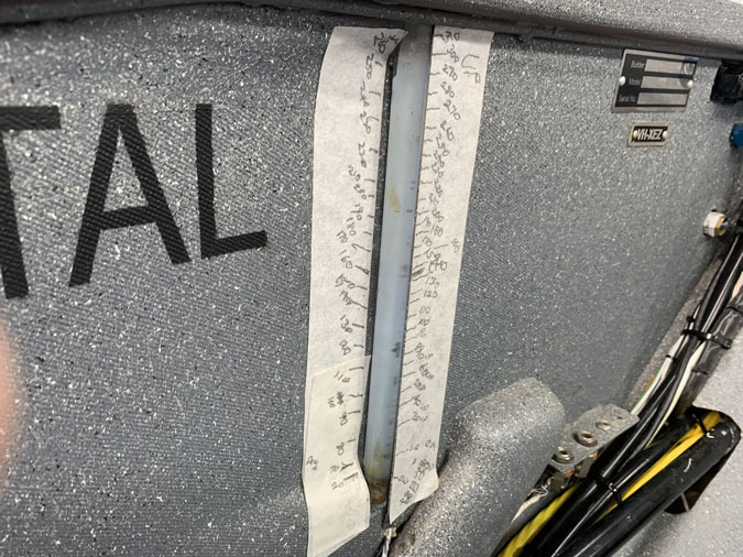
These fuel level labels were tough to make. I put 14 hours down for the time, it was probably twice that.

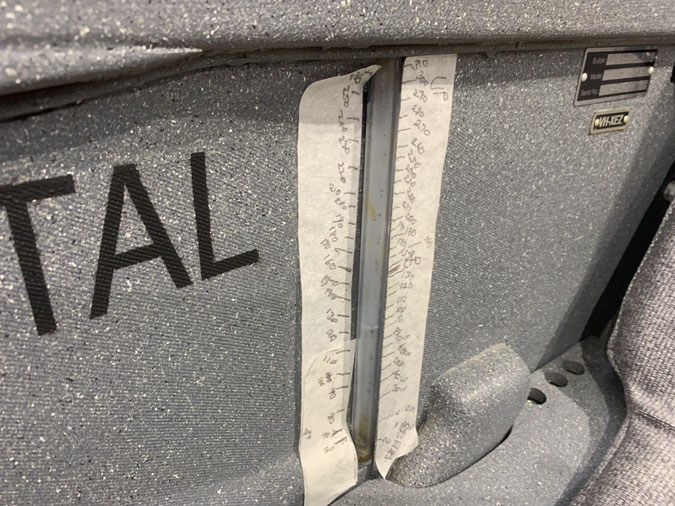
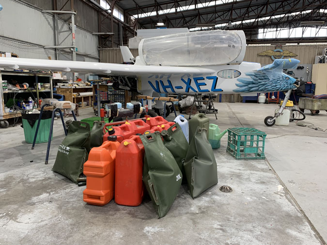
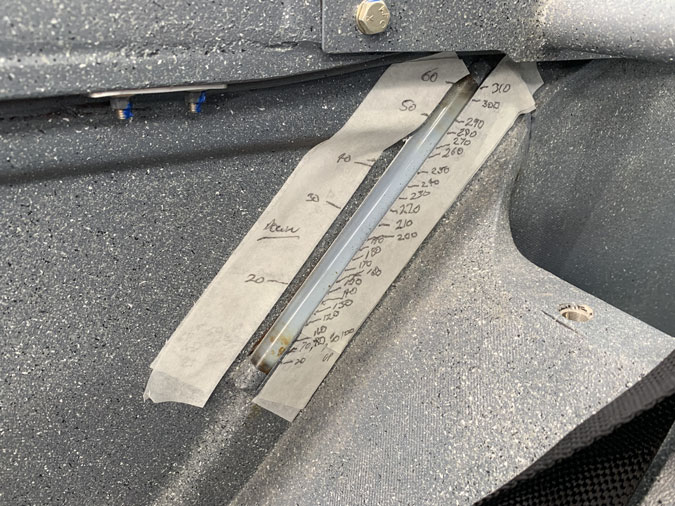
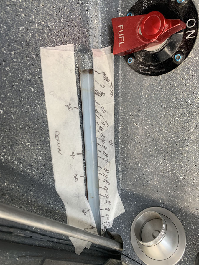
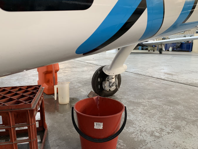
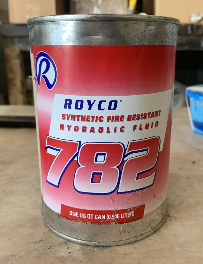
This is what I set up when pouring fuel into the wings in 5 litre increments. The markings are every 10 litres.

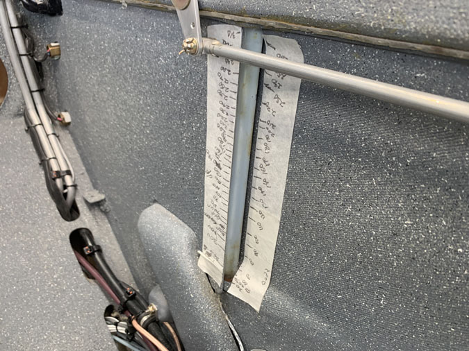
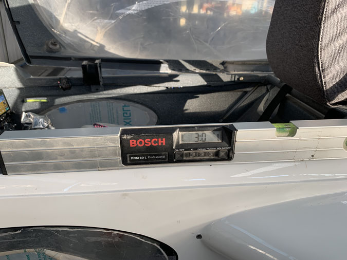
Converting the marks on the tape to something I could print out in Word on my home printer took forever. It was very much trial and error. Print where the marks go and comparing this to the marks on my tape. You have to go from the top down and I was increasing or reducing the size of the spaces one point at a time. Then I’d print and check my work. There were eight labels to do!

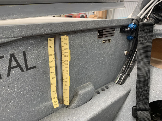
This is printed out on yellow cardboard. I played with the angles on the rear one as a sort of triangle mount like Toblerone chocolate.

The front labels on this angle took a bit of head scratching to make something printable. Angling the text didn’t seem easy at all but a graduated number set to a line worked well.

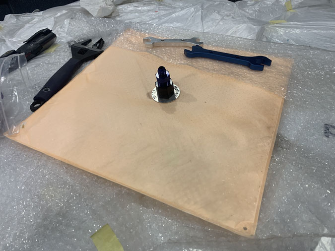
I’m skipping a few steps here. I found some CriCut inkjet clear printable labels that you then apply a plastic coating to.  The material I’m mounting on is G10, a compressed fiberglass that is quite strong. I had some very thin stuff left over from an earlier part of the build. I’m using this as just gluing a label onto the fuselage side would end in tears. The surface is too rough with the textured paint. Better to mount on a solid smooth background and silicone that to the sides. This also makes them easily removable.

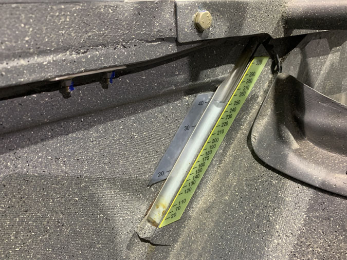
Next up I painted the back of the G10 yellow to highlight the numbers even more. I used grey paint for the front or ‘nose down’ labels.

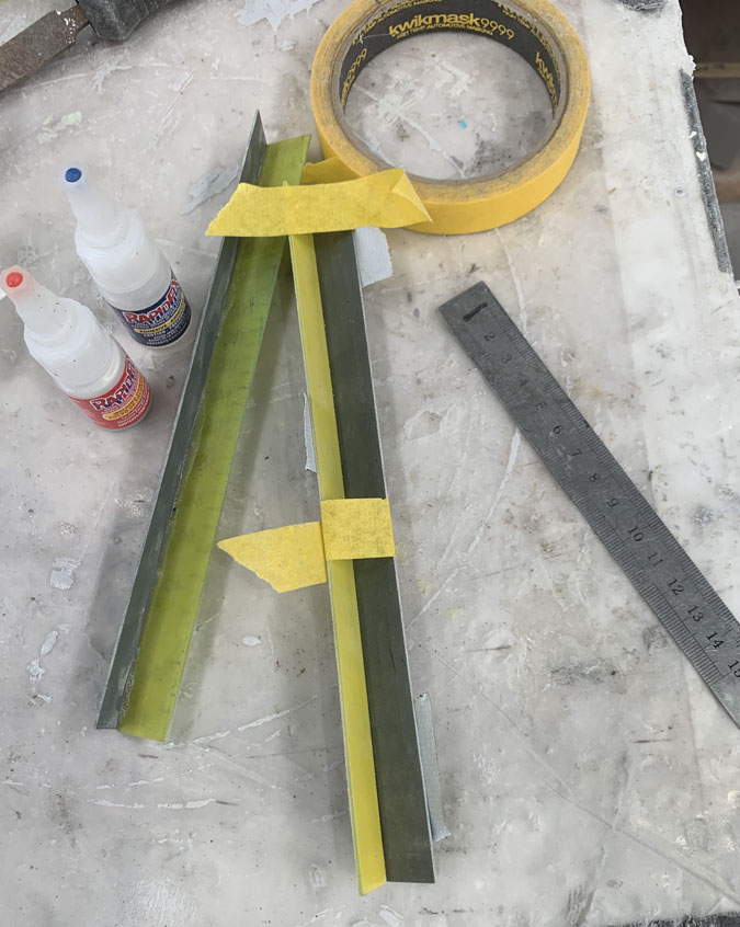
The pic is two sides of the triangle. I’ve taped them together and then run superglue down the seam. Next I used some powder that soaks into the glue and makes a really strong join.

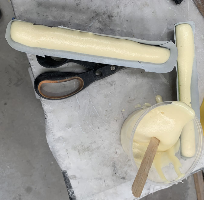
This is pour foam to fill the triangles. I want a backing surface for mounting.

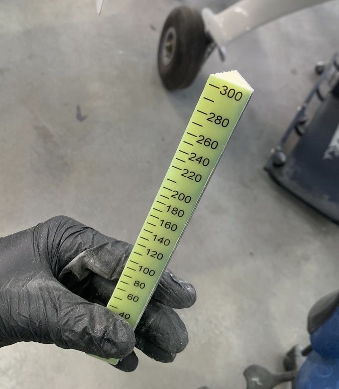
Here’s the finished result ready for mounting.

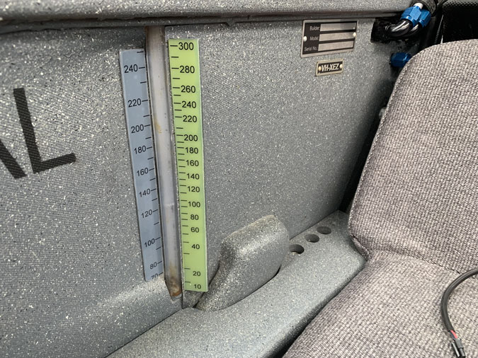
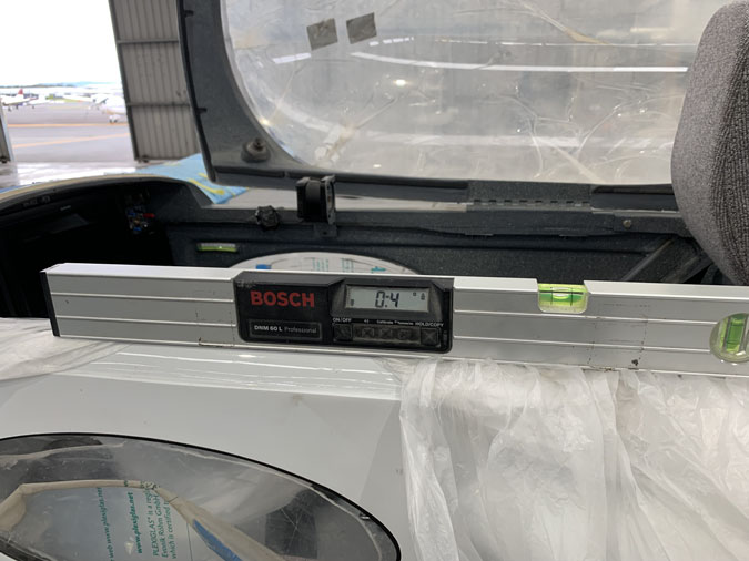
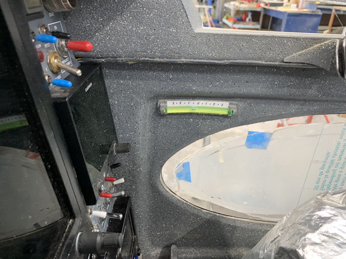
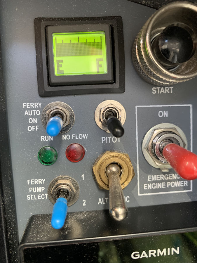
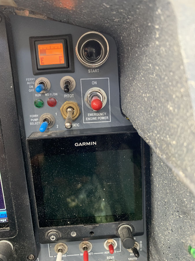
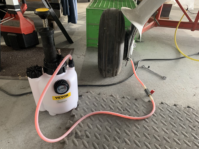
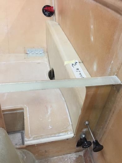
The angle is so I can see it from the front seat. The grey label in the front is when the nose is down. You might look at this during refuelling. Its not something relevant in flight where the nose is slightly above level. Probably around 2 degrees. I’ve done my calibrations at 0 degrees. Flight tests will determine if this is an important difference. If it is, I can move the back or inflight label scales

The front seat was challenging but here we are. Readable fuel levels. Overall I am not happy with my work. I will get it done more professionally some time later using stuff called Traffolyte. For now it is a massive upgrade from a bit of tape!


Fuel Calibration1 How much does it hold?

Date:  08-09-2024
Number of Hours:  18
Manual Reference:  21

The strakes on this plane have been modified to take more fuel, a lot more. The downside is that I had to give up very valuable baggage space.  I still want both. I could have left a little bit, a pocket or two for lunch but that’s now way too late.

Many years ago now, I planned how much fuel I could fit in without making the cockpit baggage cutouts. I did this old school with graph paper and dots to count the squares! My ‘skills’ said I could fit 300 litres rather than the plans 200 litres. Then there is the common sump which I was thinking might be about 15 litres or so. Now was the time to find out if I had 315lts!

First up was getting that much fuel in bags or cans so I could slowly transfer it to the tanks. Not only do I need to know the maximum I can hold but I wanted to calibrate my forward and aft sight gauges.

I needed two readings per quantity. Nose up near flying angle would give me flight fuel and nose down would give me a guide when refilling on the ground with the nose down.  Flying attitude might be nearer 2 degrees, but that’s not going to happen on the ground!

I soon found that even .4 degrees nose up had the plane tipping backwards onto my ‘safety catch stand’ once there was a bit of fuel onboard.

I get a good reference line of the longeron position in the cockpit.

You can see the level on the longeron here, I went with zero degrees as the difference is slight for fuel quantity and the airplane will not tip backwards without encouragement.

So zero degrees. We are good to go with what become a very long day and night. I put 5 litres poured into a calibration watering can’ (one that had marks on it) into each tank. Even though they cross feed I didn’t want to wait as I don’t know how long it would take for the various levels. Then I’d put a mark on each sight gauge tape. Next I’d lower the nose and do the front, nose down marks.

Front right side. Yes its a lot of marks! You can see how the nose down position isn’t much use after 60 litres.

Left side front. The gauges are full here.

Right side back. I bet you are wondering how am I going to read the graduations by turning around from the pilot seat in flight.

Left side gauge. Yeah, I don’t know yet how I’m going to size nice readable printed labels either! This day went well into the night, but I did get it done.

With the tanks absolutely full. I got 310 litres. Within 5 litres of my estimate years ago. Very smart or very lucky? I’ll leave that to you.

The next huge task was the calibrate my AG6 fuel gauges. First of all they didn’t work at all so. I had not plugged a lead in correctly, then the readings didn’t work. My very skilled avionics guy figured it out.

The gauge graduations go off voltages that come from these liquid sensors. It was set up for 12 volts not aircraft 14volts. We added a pull down resistor and that sorted it out.

Here is the full indication.

So called 3/4 is only about 20litres or so less.

So on it goes. While I put the sensors roughly equal distances apart they don’t reflect equal amounts of fuel remaining.

I will have to revisit the programming of the button gauge and set the graduations more appropriately.

I do know if I see this empty gauge or the Low Sump warning that follows I’ll have about 14 litres of fuel left and I should already be on the ground.

I do need to recheck these marking indicators in flight. Overall, I’ll be going by the cockpit sight gauge graduations and the fuel burn on the Garmin G3X/GTN750 which once calibrated should be super accurate.

A little ‘bonus’ is that with the tanks full of course the vent lines are covered. I get a very slow leak through them onto the ground. I found that tipping the plane nose down a little stopped the leak. Then later it started up again and kept slowly dripping until the temperature of the hangar dropped a few degrees, then it stopped again.

If I fill up overnight I need to have a catch bucket and watch the temperatures in the morning, or just fill before I go. I’m thinking if I need to be that full its going to be a long flight and an early start!


Unusable Fuel or 25 seconds

Date:  07-12-2024
Number of Hours:  2
Manual Reference:  23

How much of the fuel I put in is unusable? In other words, can the engine use every drop I put in the plane?  Or does some of that fuel, because of the position of the fuel pickup in the bottom of the sump tank, make that last little bit inaccessible in flight? I had to know.

Given my fuel pickup is in the middle of the sump using that holy hydromat filter, I figured that coming in on a 3 degree glide slope would be a good test. This is less favorable that straight and level and more likely if I was going for a landing zone. If I was onto the bottom of my reserves this was the scenario that would be useful to be sure of.

With fuel running into a bucket my method was to watch the 35psi pressure and when it dropped I would have run out of fuel. Then  I could measure what was remaining.

It turned out that at the 3 degree the fuel stopped draining out and kept recycling. So with whatever was left it was enough to wick up the hyromat and still given me full flow.

I shut down the pump and had to really lower the nose nearly to the ground to get the last bit of fuel out that would be ‘unusable’. This is also the deck angle I need before flight to check for water in the fuel sump daily and after refueling.

This turned out to be only 0.4 liters or 400ml. Now lets say at a very conservative 30 liters an hour this would be about 25 seconds or so of engine time.

Interestingly if the nose gear is all the way ‘up’ when parked, fuel will move from the sump tank to the wing strake forward tips. If there is only 10 liters or so in the sump then it will appear as if there is no fuel in the plane. However as soon as the nose is raised a little, it flows back into the sump. I don’t see this as a problem as 10 liters is not exactly flight fuel and even a slight nose up gets it back to fill the sump.

You know, I just might live dangerously and call all my fuel usable, rather than take off 25 seconds of my calculations with this plane’s endurance. My instructor would correctly say, take off a full minute. If it ever came down to that, I would be too busy at the time to change actions and I might just save another extra calculation for every flight I plan.

What do you think?


Sump Hatch 2

Date:  06-13-2024
Number of Hours:  4
Manual Reference:  no ref

The time has come to close the common sump. I did the hatch window in Sump Hatch 1. Now its time to finish the job.

https://alongwayroundtheworld.com/wp-content/uploads/2024/06/FuelDrain.mp4

First up was to use compressed air in both the wing tanks and the sump to get as much gunk out of there as there might be. Next up I grabbed 10litres of Avgas and put 5 in each wing. I used Avgas after some advice… because mogas stinks!

This was the first time the tanks have seen fuel and I got to see how well the common sump drains.  It gets everything down to the low point so that works. No leaks either. All good stuff. Then I got to drain it all out and see if there was much residue. Once all the fuel was gone there was a little bit of stuff left in the sump which I cleaned out meticulously.

This is the Holy Hydramat, that is going to live in my sump. Its a 15 micron filter 15″ x 15″ and a genus design. I get a huge area fine filter before it even gets to the pumps, then I have a 10 micro cleanable filer after that before we get to the engine. I should have clean fuel and no worries about a filter getting blocked.

With a now flushed and cleaned sump I got the Hyramat back in and fastened it with two small nuts in the tank. I connected the AN-6 fuel hose, confirmed tightness and it was finally time to button it all down.

The gasket is 3mm cork impregnated with neoprene or something. It is fuel safe, that much I know for sure! The resident sheet metal guy in the hangar thought that my bolt holes should have been closer together and thats why he suggested the 3mm rather than 1.5mm cork. I’m using a gasket ‘dressing’ that gets smeared on both sides of the cork to aid sealing.

Here it is sitting on the flange during a test fit. I was really careful when I made this to mark which way it goes on so the holes would line up exactly. You can just see the marks.

After the thin sealant and setting it all up, I spent some time getting things aligned and then progressively tightened. I did this with the screws in an opposite pattern as we do when putting on propellers.

Here’s how it looks. The sump is secured. The fuel path is done for now. I still have a couple of hoses on top of the engine to do however but this side of the firewall forward is all good.

Sump Hatch 1

Date:  05-23-2024
Number of Hours:  5
Manual Reference:  n/a

It is getting closer to the time when I put some fuel in this plane. The sump viewing and access hatch needs to be sorted out.

I made this years ago. The idea is that the sump hatch has to be accessible because I am putting a big Holley Hydramat fuel cell pickup filer (11″ x 11″ and 15 microns) in there and one day it may need to be replaced. I also wanted to be able to look inside the sump to check the filter.

After quite some research I settled on the Gasket Dresser and old school cork 1.5mm thick to seal the window area.

This means two cork gaskets. I just cut them from a sheet., The cork is impregnated with Nitrile so not fully old school.

This is the sandwich.

Here’s the sandwich ‘deconstructed’ just before I put it all together. I used the gasket dresser material smeared on both sides of the two corks for the four bonding surfaces.

Assembly was slow but simple.

I was careful to tighten the nuts in a cross pattern. I did get a little squeeze out as I went. I am confident this hatch has a good sealed window now.

Piss Tube, Hammer, Fuel Run and Brake Fluids

Date:  11-04-2022
Number of Hours:  12
Manual Reference:  no ref

A few more little jobs while the wait for the engine continues.

The piss tube is in place now with velcro and some soft surgical line at the end of the PVC tubing.

The soft section of tube takes bends really well and allows the tube to be stored out of the way easily.

Here’s my canopy breaking tool which I don’t expect to ever need. That’s why I have it. Its well within reach if I ever have to bust out of the canopy after an accident. Its also well out of the way for normal times.

With so little to do while I await the engine I put a few fuel lines back in.

I had to have a think about where things went. Its been a while since I worked all this out.

Its really a very simple system, until you have to make the hoses and get them in place.

A few details not in this simple drawing….The Hydromat filter is 15 microns and the post pump/pre engine filter is 10 microns. I have two vents in each main wing tank and a vent in the common sump all going to a common manifold in the turtleback. They then go down to the bottom of the plane. Each vent at the drain point has a heater in case they become blocked due to icing. They get turned on with pitot heat. We all need a little excitement.

This is what I used for the canopy seals and any other rubber parts that need fixing in place. I just wanted it somewhere in the blog… sorry for the interruption.

This is the brake fluid I will not put in next week. It is very much standard aviation stuff they use at the airport. Its the old MIL-PRF-5606  BUT I do have something better that I will use instead which is much safer for high temperatures should I have a brake heat issue.

Here’s what AC-43.13-1B  says about brake fluids…

Royco 782 which is MIL-PRF-83282

Bottom Line: MIL-H-5606 has been replaced with MIL-PRF-83282 (good to -40F/C) and MIL-PRF-87257 (good to lower temps). Each of these fluids, and their associated systems, are compatible and miscible with each other. You can mix any combination and/or amount of these fluids together without any ill effects.

If, and/or when, you change over from MIL-H-5606 you can either:
1. drain your hydraulic system and refill with MIL-PRF-83282 or MIL-PRF-87257, or
2. merely top off the reservoir with MIL-PRF-83282 or MIL-PRF-87257 as needed.
Both methods have been used with great success with no reported problems.

That said, I would ASSUME mixing the two would reduce the fire protection you get from straight MIL- 83282

This unit lets you pressurize the line. I added a stop valve as I’m filling bottom up and need to check in the nose how I’m doing before I get brake fluid everywhere.

I did get a scare as this is my first time and it seemed like the line was blocked, which would have been an issue. I did blow some compressed air through and got a bit of advice and someone else to watch the bubbles and eventually the fluid come through.  It needed about 15psi which required that I hold the fitting in place. Yes I did have a little spill to clean up.

Here we are at the nose. I didn’t fill the reservoirs all the way as when the nose in lowered they might spill out the top breather holes. I will be watching the first time I lower the nose all the way to the ground. That will be the MAX line which I will mark. For now, I have brakes!


Fuel Tank Vent Lines

Date:  09-17-2019
Number of Hours:  28
Manual Reference:  no ref

Before I start prepping the fuselage for paint I want to get a few jobs where I’m climbing in and out of the rear seat done and dusted. Sorting out the fuel venting is one of these.

I revisited the fuel manifold which was set up for plastic line inserts. I removed these and bought some pipe fitting inserts to replace them. After the old inserts were out I added a 3 ply layup over the holes ready to be re-cut.

The new fittings are now in place. I had gone from copying the method from another website using the plastic to going full 5000 series -6 (3/8″) solid fuel lines. I’m not even sure how my thinking changed except to say that solid lines are the logical choice as I am extending the fuel system through the cockpit area.

I spent a couple of days getting here. Refining my techniques, learning about flaring tubes properly and making the nice curves.

I love this flaring tool. With practice it gives a great result.

Only a builder might be interested in my clean flare.

Many many more hours and several tries before I got some of the longer lines sitting in place.

Some crazy shapes and bending skills were needed here. Not perfect for sure, but better than a few days ago.

See what happened here? The curved lines are gone. A ‘proper’ aircraft craftsman had a look and thought I could be neater and better. I remade all those top pieces. A lot of attention also went into how the pipes will eventually lay together. We discussed various methods so that they would not rub and chafe with the airframe vibrations.

Here’s a long look. I’ll revisit this when I have all the firewall penetrations sorted out. That’s when the adel clamps and ties will ‘nail’ it all down.

We have two vents per main tank, one vent for the common sump and two outlets under the plane from that common manifold.

The vents exit under the plane. These are removable for now he finishing is done and the final fasteners, then I will shorten the tubes to about an inch, cut them at an angle and flox them in place at the bottom.

The vents are done for now. Fastening them is a job for after the firewall penetrations are sorted out. I’ also want the hellhole items settled. Where things are now I can move the vent lines a little to accommodate what might fit in these tight places.

Fuel System – Pressure Regulator Part 2

Date:  09-18-2017
Number of Hours:  4
Manual Reference:  no ref

In pics 1 and 2 you can see how it all fits in now. There is even room for the two black heater pipes. I have spent hours playing around with the hose outlets at the rear of the arm rest and sorting out where they will go in the hell hole area. No pics for once just time served.

Pic 2 shows that really busy area like I’m building more than just a fiberglass bathtub.

Pic 3 is my happy place where the on/off valve is located. You can also now see the two push/pull cable controls for the heat system. The trap door or incoming air valve also has a lock on it. So when you turn the knob it locks in place. If I want it shut, it will stay shut. The other knob controls the direction of the hot air, forward back or a mix. I have no idea what will wok best.

By the way I now have black screws for the On/Off fuel valve. I couldn’t get anything locally so they came from China with free postage and about 8 bucks for a bag of them.

Fuel system

It all fits

On/Off fuel …and the heater valve controls

Fuel System – Pressure Regulator Part 1

Date:  09-17-2017
Number of Hours:  6
Manual Reference:  no ref

The placement of this fuel pressure regulator has gone on for several months. I have even ordered two parts from the USA, both of which didn’t do the job. In the end a very knowledgeable friend and engineer, Gary Hill, showed me that I can pull the valve apart safely and change the orientation of the in/out pipes.

Finally I have mounted the unit using click bonds. Initially a stick jammed into the rear cavety (if you’ll pardon the phrase) held the unit in place for the first cure. Pic 1 shows the duct tape covered result. Next up was to do the usual clean up and a couple of very small plys of BID over the top. The result is in pic 2.

Pic 3 shows the regulator fitting in the arm rest area, It will take the engine return line through the -6 fitting at the rear. I’ll go the flexible hose here. The fuel then gets ‘regulated’ in the body of the unit to the common sump. Somehow in my brain that doesn’t seem right and the regulator should be in the ‘before the engine flow’ but I have the EFII drawing and its all good.

Regulator

Regulator clickbonds

Pipes in place

Fuel System – Strake Outlet Pipe Part 2

Date:  09-16-2017
Number of Hours:  6
Manual Reference:  no ref

The old hard point had to come out and it didn’t want to. I won. Pic 1 shows where it was, you can see the peel ply yet to be removed. Now this area is well repaired with a couple of glue cycles and more of my precious fuel safe epoxy used. The new straight bulkhead fitting is in place. I have moved that hard point 2.5″ to the rear. That’s what was needed.

Pic 2 shows where it is in relation to the feed pipe from the strake. I am using a straight fitting because I have discovered the 90 degree -6 Speedflow fittings which are ideal here.

Pic 3 and you can see a nearly straight pipe going to the on/off valve. Its fits well and is more ‘relaxed’ than the other two attempts. The hose has a slight bend in it for strain relief although it is not under stress. Yes now I’m happy.

New moved hardpoint outlet

Side view

It works, I’m happy

Fuel System – Strake Outlet Pipe Part 1

Date:  09-15-2017
Number of Hours:  6
Manual Reference:  no ref

My first difficult fuel system hose was from the sump outlet to the Andair on/off valve. Then the fuel goes onto the pumps, filter and then to the engine.

I tried making this short hose out of aluminium hard line. I got it bent and with fittings eventually. I was not happy at all. There seemed to be a lot of pressure at the joins to make it fit and I had no trust this would never leak. It MUST never leak.

I bought some teflon hose with the SS braiding and made up a short hose for that. This is pic 2. HEY! I’m still not happy. That hose has quite a bend in its short travel.

Lets face it I have put the outlet and the on/off too close together. Why? Well when I did the hardpoints I didn’t know where the feed pipes were going exactly so I stayed forward of that area. Now the pipes are in I can go right next to them. Yes I can move that hard point although its going to be a bit of work and it MUST not leak.

Pic 3 shows I’ve made the inlay, I have an aluminium hard point tapped for the fitting AND I’m going for a straight fitting rather than the existing 90 degree one.

Seems like a short hose

I’m not happy

Moving the hard point

Fuel System Getting those Ducks in a Row 4

Date:  08-26-2017
Number of Hours:  2
Manual Reference:  no ref

Pic 1 shows a bit more work has been done. After the base click bonds were in I made some floating nut plates up and embedded them in the sump wall. Again using a stick on the assembly and release tape. I then went ahead and did another click bond thing for the Adel clamp what will hold the post pump filter. A bit of time went into pic 1.

Pics 2 and 3 show you the assembly in place. I have gone to enormous trouble with a lot of thought and time to make this work. It just didn’t seem to be possible to make these items fit in here at first. I had to source fittings I didn’t even know existed. Now its done, it looks easy, simple and why was it a problem in the first place?

Buy me a coffee sometime and I will explain.

Click bonds and nut plates

In place from above

In place, the ground view

CategoryLogsHours
All157617079
Uncategorized135
Ch 3 Education220
Ch 4 Fuselage Bulkheads25231
Ch 5 Fuselage Sides32283
Ch 6 Fuselage Assembly30270
Ch 7 Fuselage Exterior14140
Ch 8 Roll Over/Seat Belts990
Ch 9 Main Gear/Landing Brake71642
Ch 10 Canard28287
Ch 11 Elevators36298
Ch 12 Canard Installation12102
Ch 13 Nose and Nose Gear1291097
Ch 14 CenterSection Spar57525
Ch 15 Firewall and Accessories448
Ch 16 Control System27237
Ch 17 Roll/Pitch Trim System654
Ch 18 Canopy70502
Ch 19 Wings, Alierons1271090
Ch 20 Winglets/Rudders71528
Ch 21 Strakes - Fuel/Baggage65437
Ch 22 Electrical System591031
Ch 23 Engine Installation961152
Ch 24 Covers/Fairings/Consoles25202
Ch 25 Finishing561084
Ch 26 Upholstry340
Fuel System46310
Rollover1050
Cabin heating System60331
The Ferry Tank335
Blog2694182
Build Mods2252513
Nose Gear Doors856
Wheel Pants/Gear Leg Fairing40473
Oxygen System762
Roll and Pitch Trim964
Winglet Intersection Fairings445
Baggage Pods11104
Pilot Side Windows437
RAM Air & Hellhole Cover15177
Main Gear Beef Up322
Post Cure124
Fire Extinguisher16
Wing Fences13
EVS (Enhanced Visual System)130
Hinge Upgrade115
Cowl Keeper110
Rudder Gust Locks19
Cooling20607
Taxi Tests42
Flying10

Complete the Test Flight Program

2025/6/30 10:26:01

Round Australia in Four Flights

2026/4/1 10:26:01

Round the World Departure

2026/8/22 10:26:01

Rough River Flyin, Sept 23, 2026

2026/9/23 10:26:01

© Copyright 2025 Dave Berenholtz