| Date: 09-13-2025 | |
| Number of Hours: 29 | |
| Manual Reference: no ref |
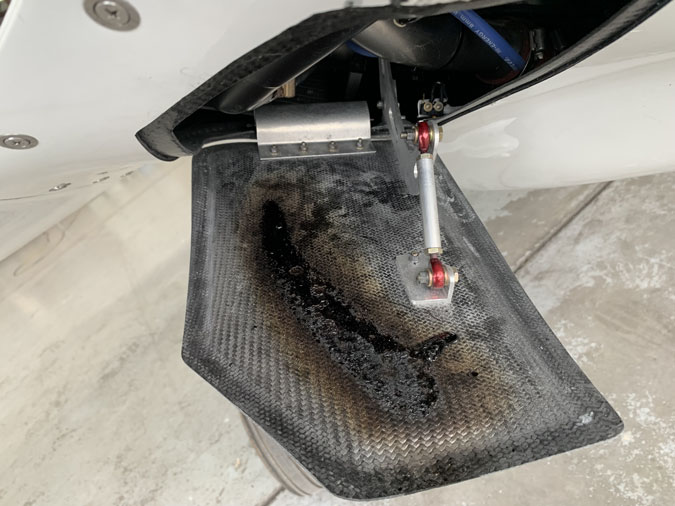
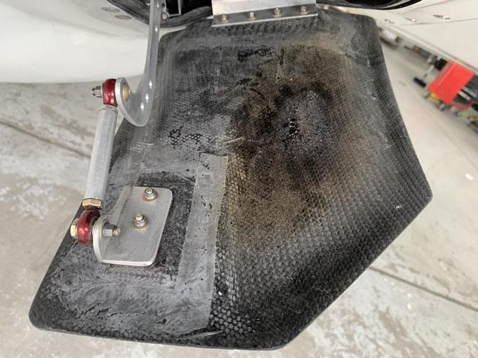
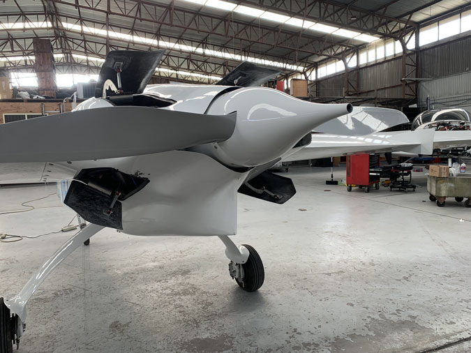
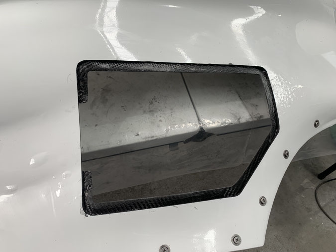
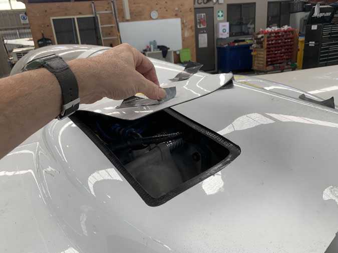
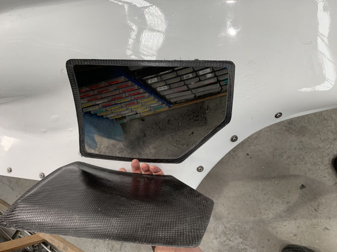
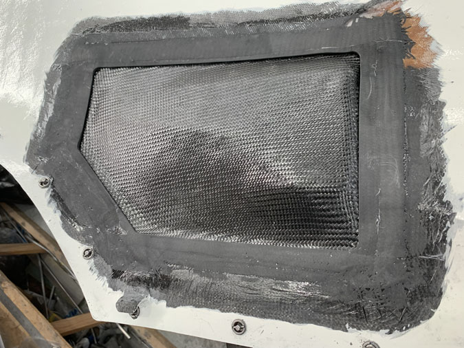
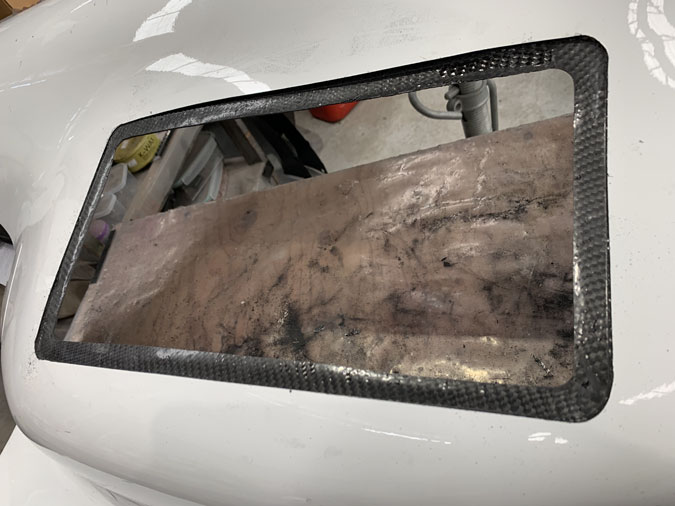
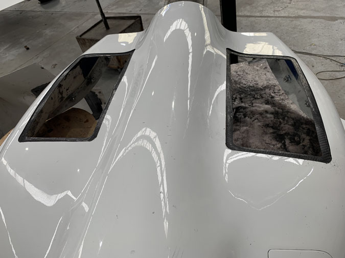
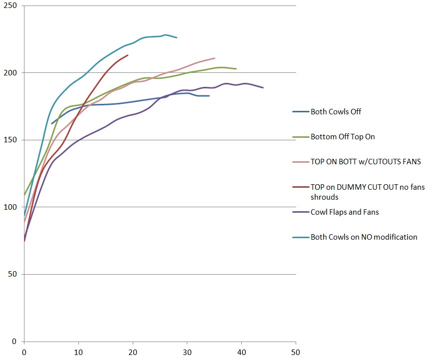
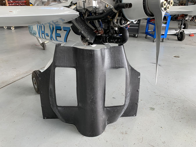
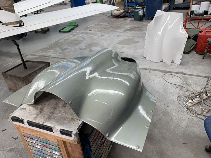
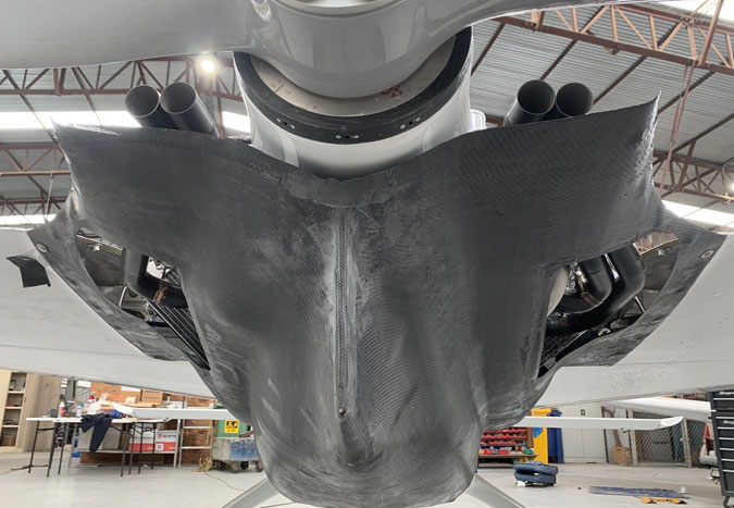
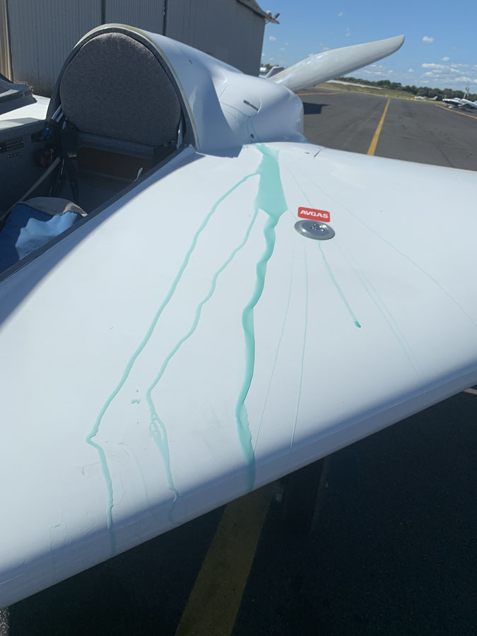
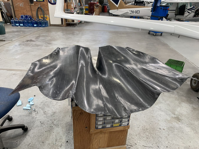
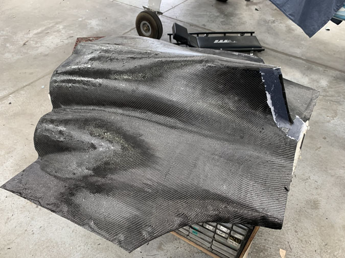
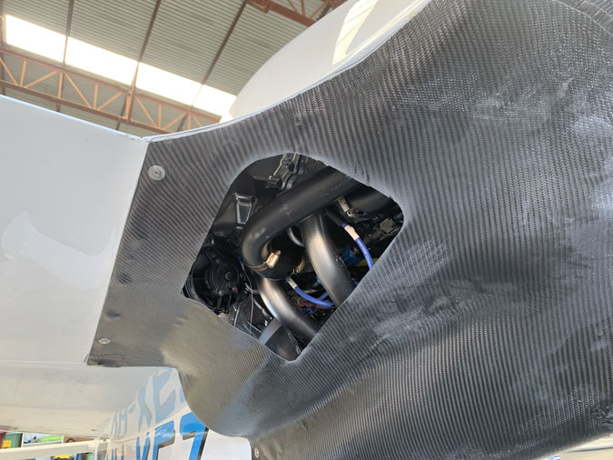
Since the first flight there has been a problem with the flaps opening uncommanded. Not all the way open but initially it was about one third, causing a lot of drag. There was no failure in the flap mechanism which was still tight, just enormous air pressure inside the cowl.
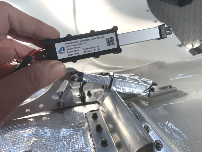
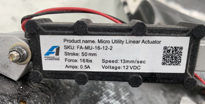
The original actuators had 16lbs of force. That seems an awful lot when you test it with a fish scale. Well, not enough so I upgraded to 38lbs of force. This is the most they make in the exact same footprint. FA-MU-36-12-2 (38lbs, 12volts, 2″ stroke)
You think that would have done the trick? It did improve things but the flaps would creep open several times a flight. Just a little bit. The actuators work on electronic stops, not mechanical. We think they were back driving in flight and cycling the flap switch would get them to close instantly. Then a bit later they would crack open again.
The drag caused was enough to change the sound of the engine and closing them again would slightly alter the deck angle to a little flatter. If I even get in an emergency situation, opening them right up would be like airbrakes! They are not designed for this as thin carbon cowls do not have strong hardpoints to mount a serious flap for regular use. I’d want something attached to the airframe and that would be another can of very heavy worms.
After a lot of thought, including some ways of doing this mechanically with levers, the decision was to go for a little solenoid latch. It needed to be as fool proof as possible. Imagine if the latch doesn’t open properly, the powerful flap comes up and breaks off the latch, it ends up in the prop and I have a really bad day.
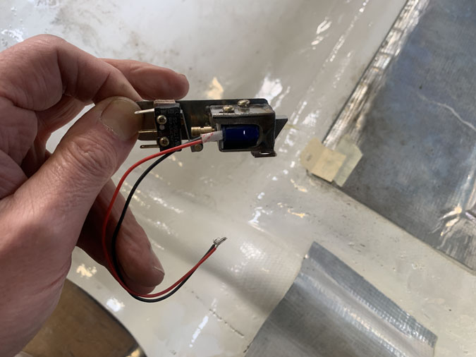
What I needed was something with an angled moving tongue and a bit that sticks out the back. The rear is to trigger a microswitch. Then of course something really clever to wire it all together with the least failure modes.
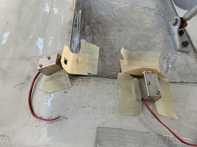
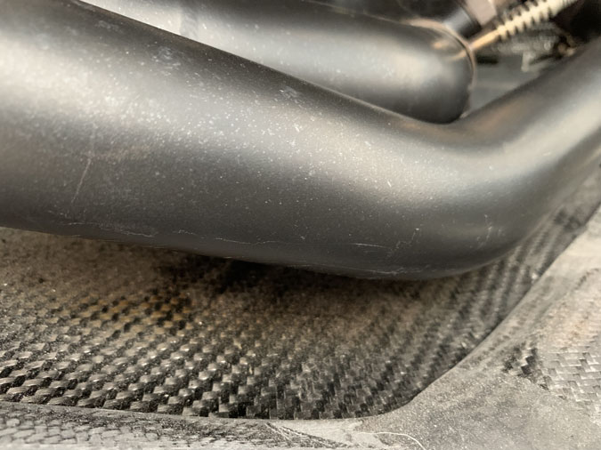
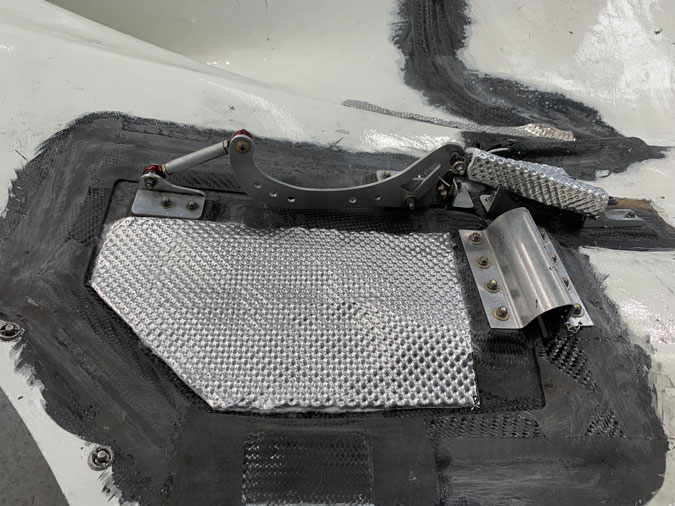
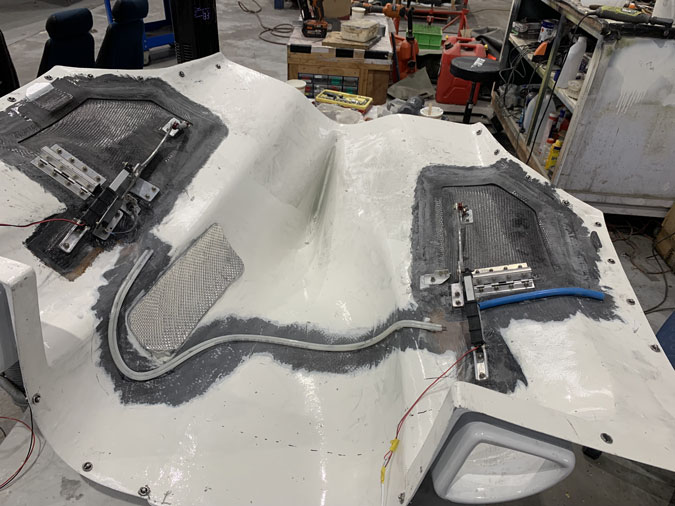
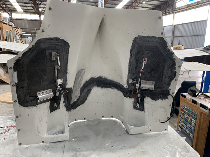
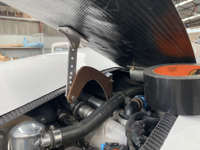
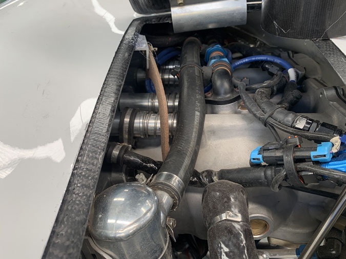
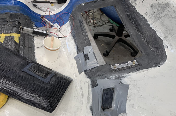
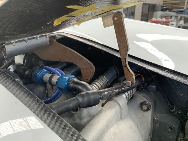
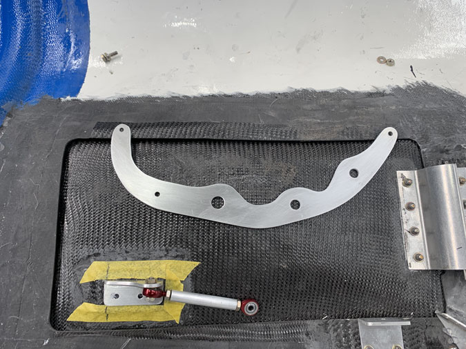
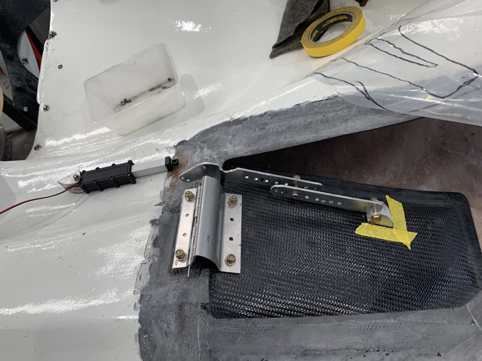
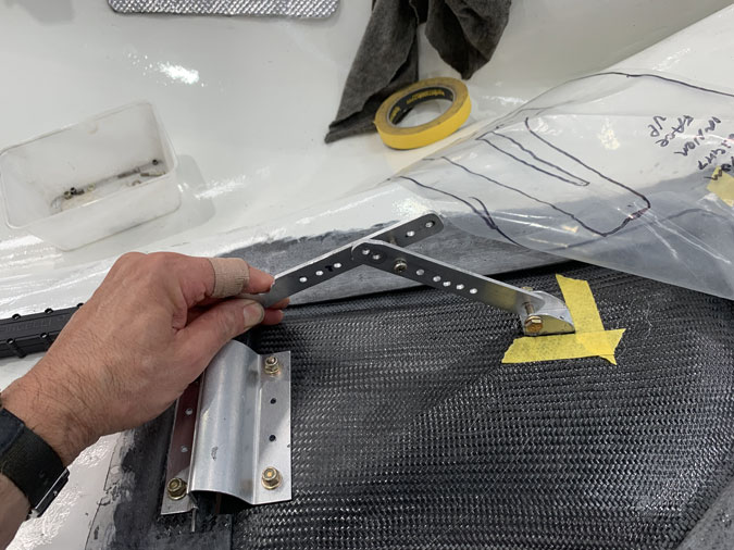
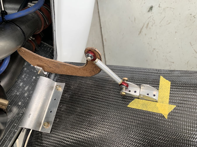
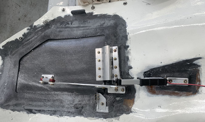
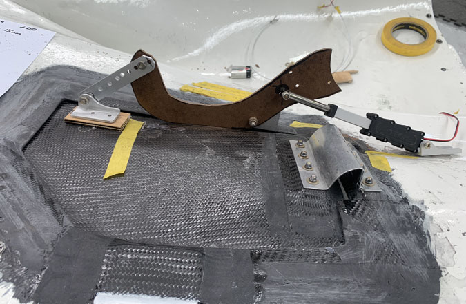
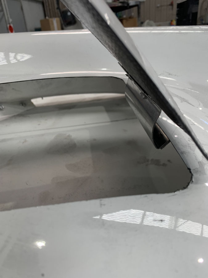
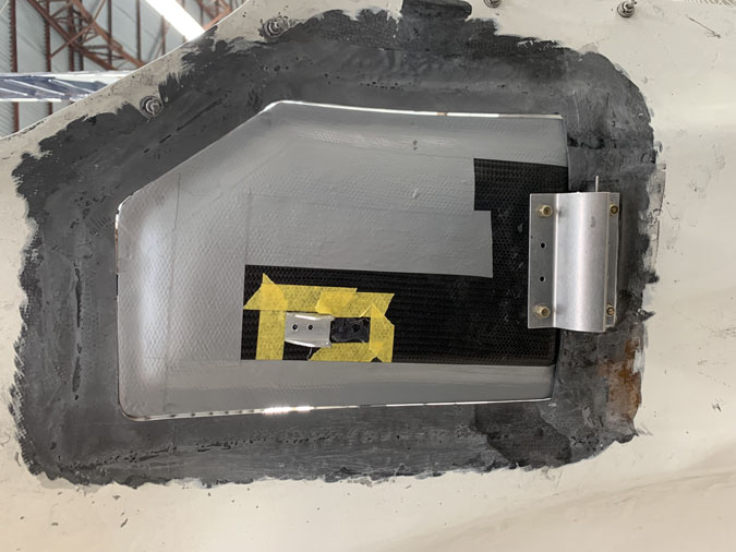
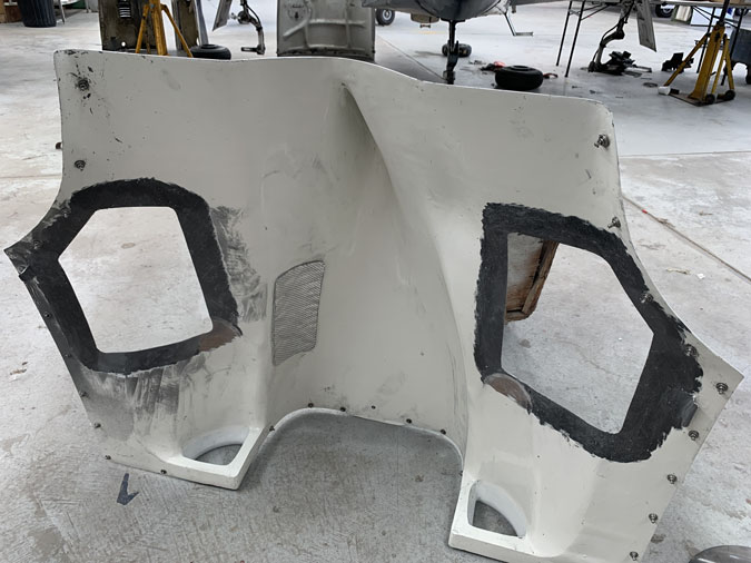
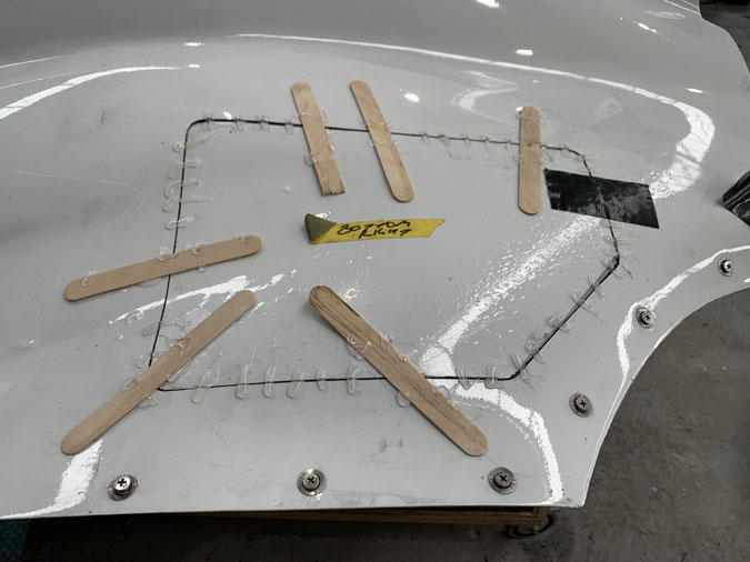
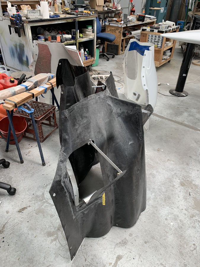
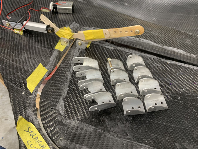
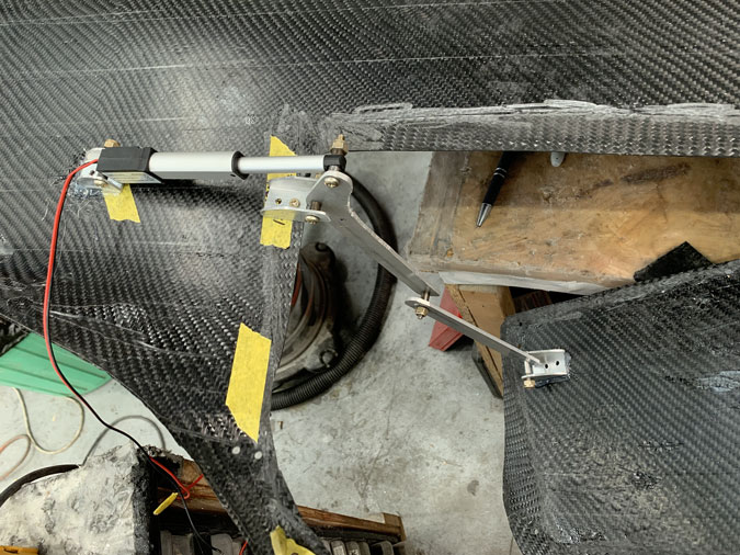
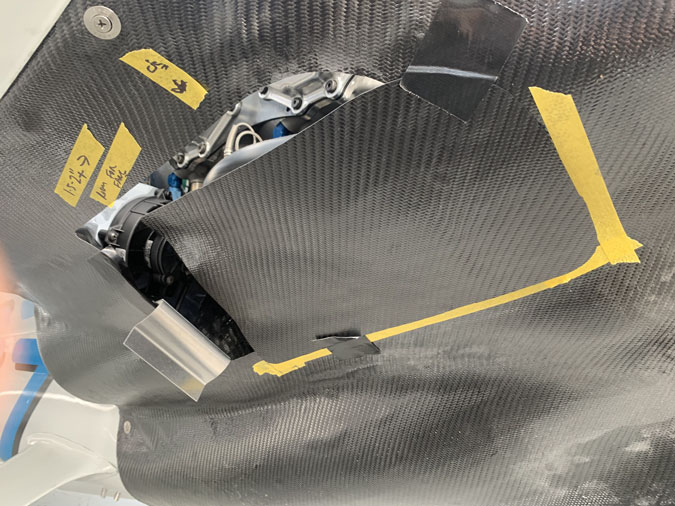
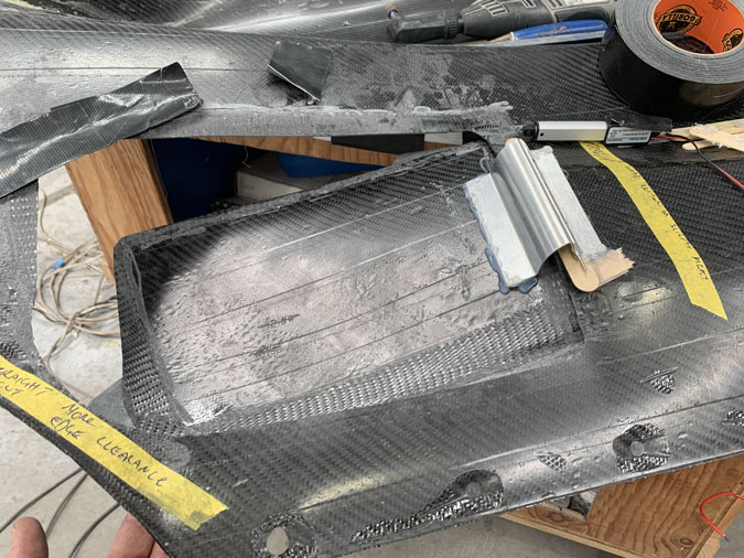
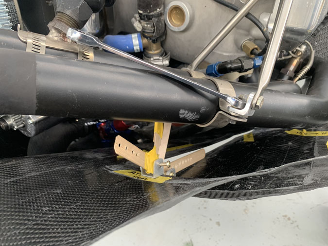
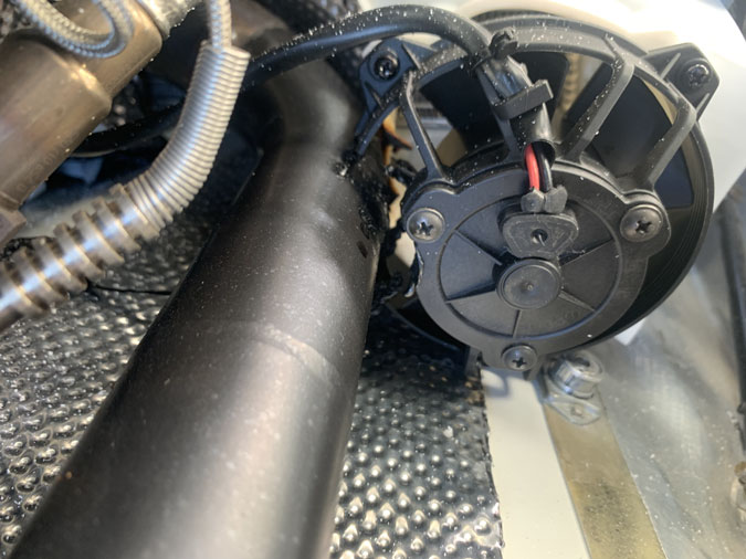
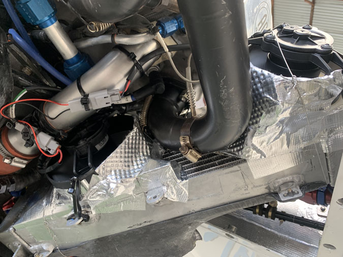
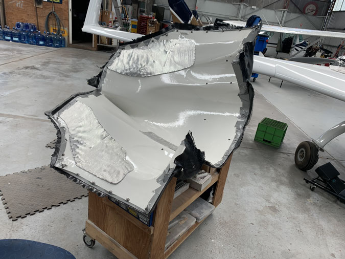
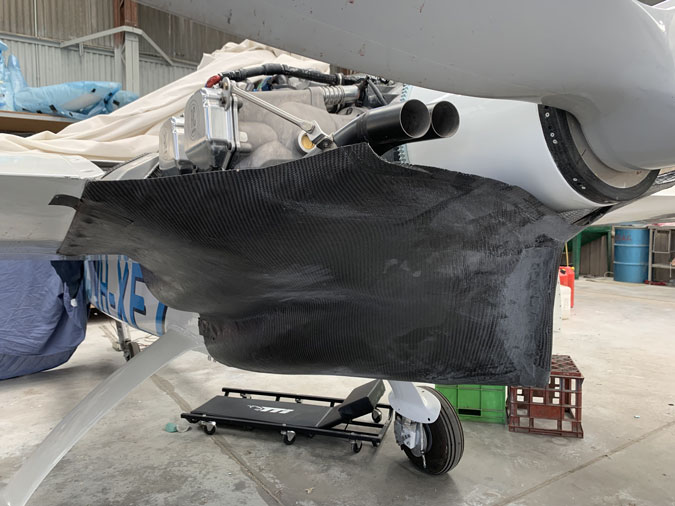
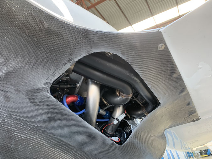
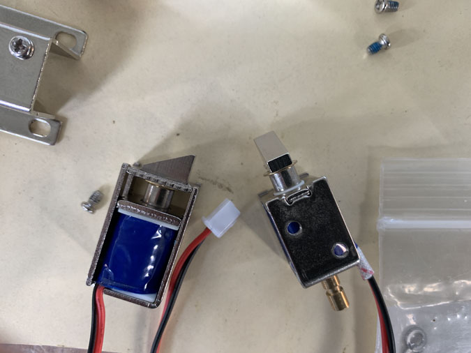
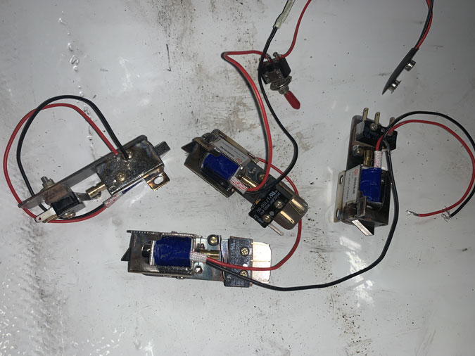
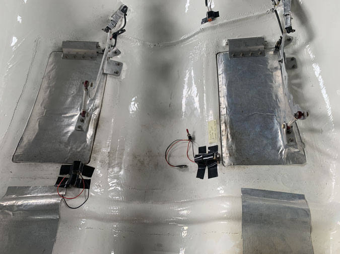
These are unmodified solenoids (no rear bit) In the middle is ideal for a latch to hold the flap but that right over the exhaust pipes and these solenoids are not rated for a high heat environment. So they are probably destined to sit on the side, have a heat shield and wrapped in insulation like the actuators. In the pic, I’m just trying out positions and thinking, one latch per flap will be enough.
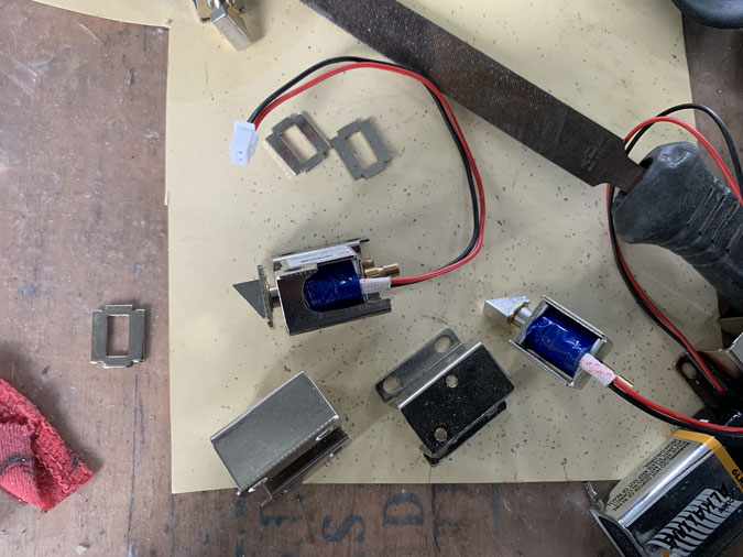
Of course I couldn’t just buy what I wanted and ended up with several sets of these little solenoids. Remember I wanted the angle, the bit poking out the back and some sort of bracket as well to fasten them. In the end two different ones looked like they could be cobbled together.
A bit more thought was needed on how to mount the microswitch. We want the solenoid to be able to tell the flap actuator we are ‘unlatched’ before it can move. Like a condition of exit. Then for closing that angled tongue would retract automatically as the flap comes down, no extra power to the solenoid needed. When powered it retracts, the tongue is on a spring, like when you slam a door. It will lock you out and close hahaha.
On the ground it would be opened, so that’s when power to the solenoid in needed, if I had a problem better then. For closing just before take-off, it needs what we already have just the flap closed and if everything is lined up correctly it should latch. Then to open, we are back on the ground again. This way seems to have less failure modes.
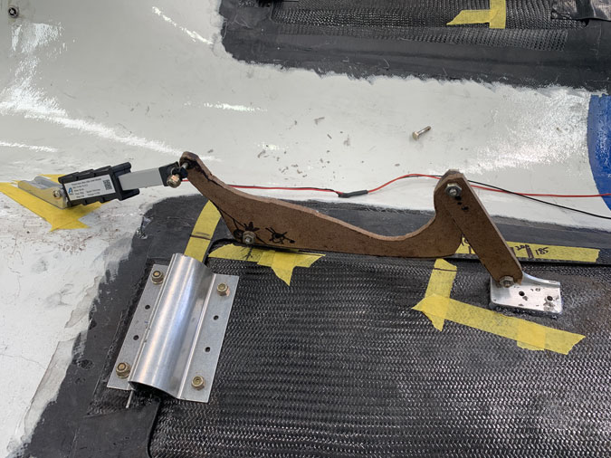
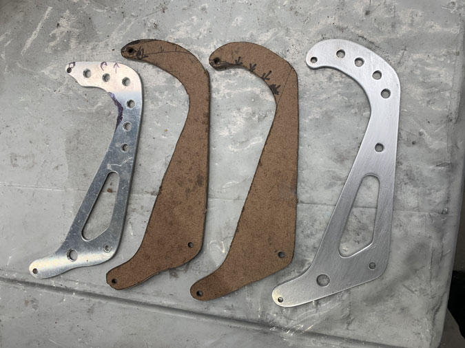
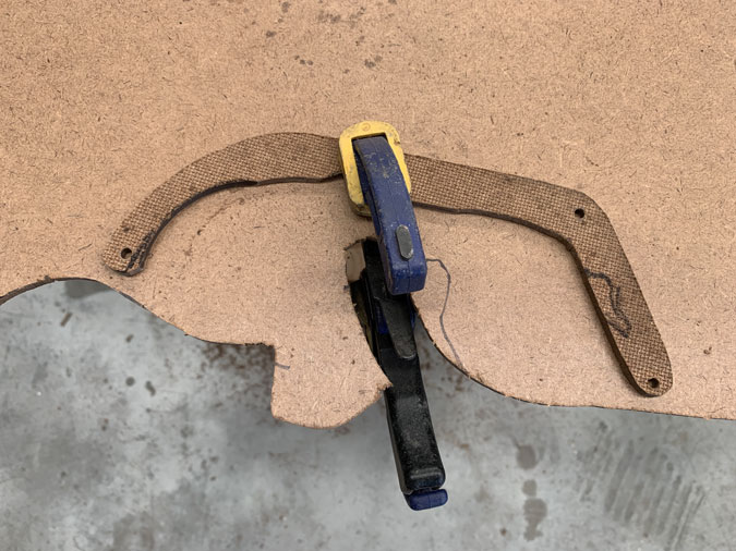
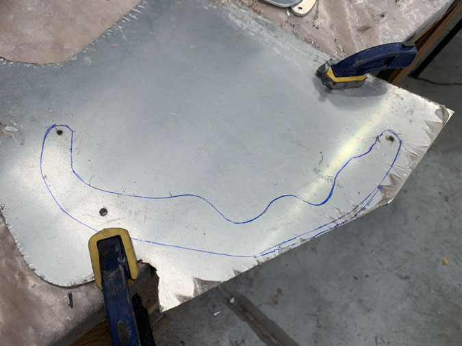
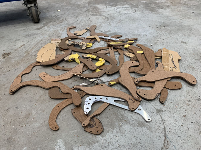
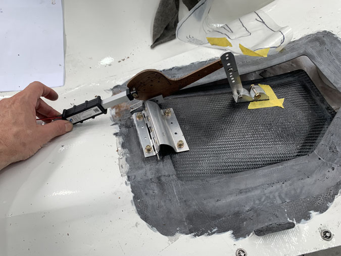
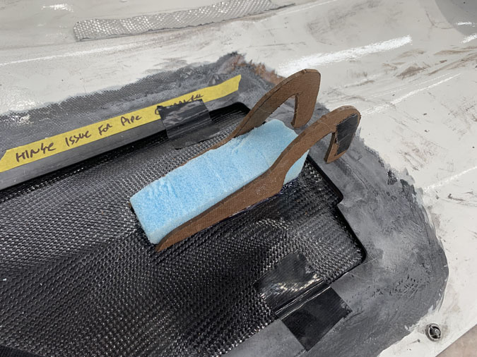
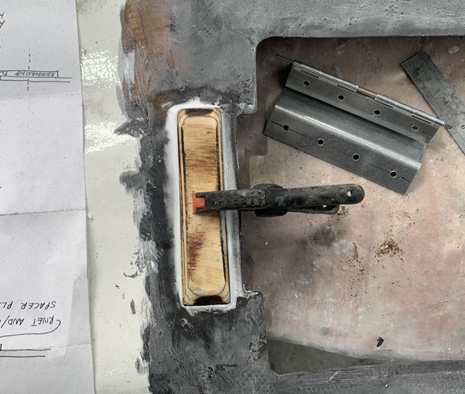
I used a bit of cardboard for proof of concept and then off to the welders.
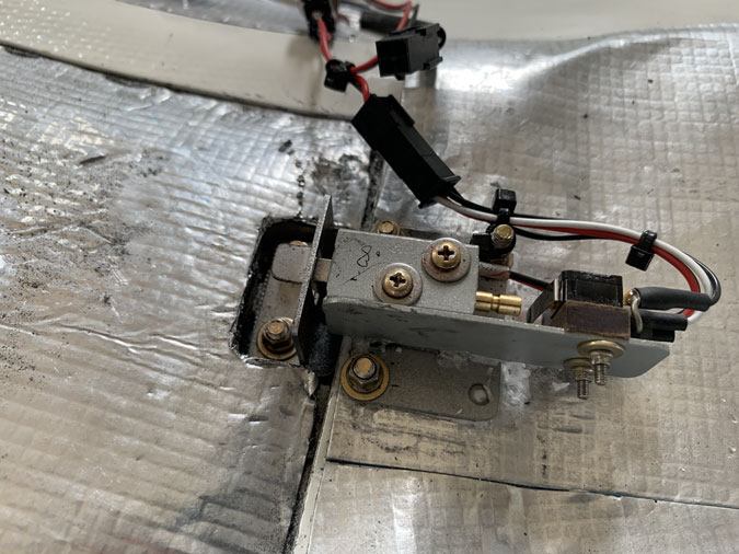
Welding was very successful, he knows what he is doing for a tiny job like this. No big blobs to file off. I did previously modify the cases as the wires on our hybrid unit were exiting the coil in an inconvenient spot.
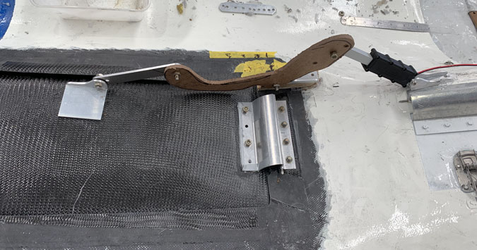
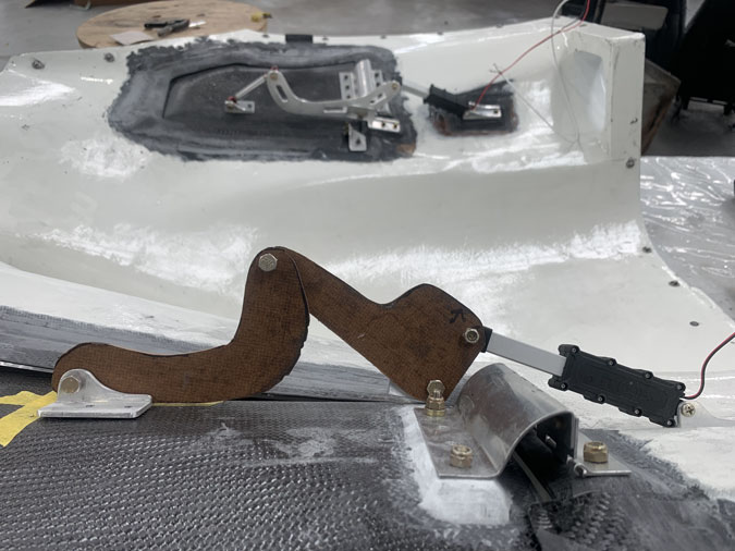
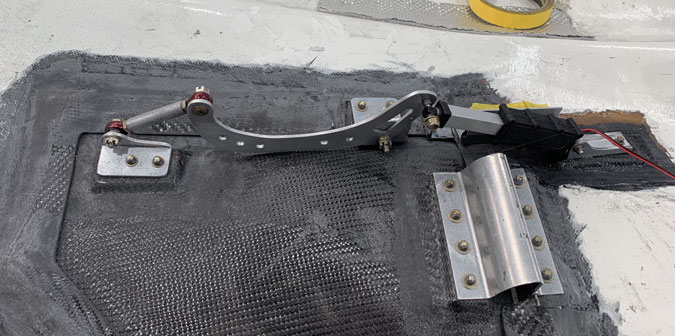
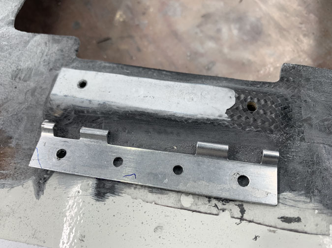
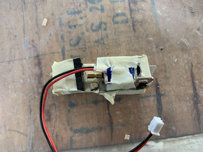
Here’s the unit with the microswitch, it can tell us when it is engaged. I had to play around a bit with screw holes and things. Its not pretty but we got there.
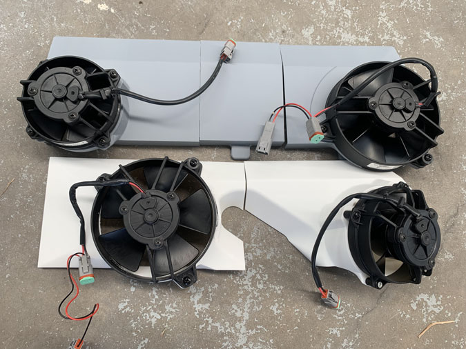
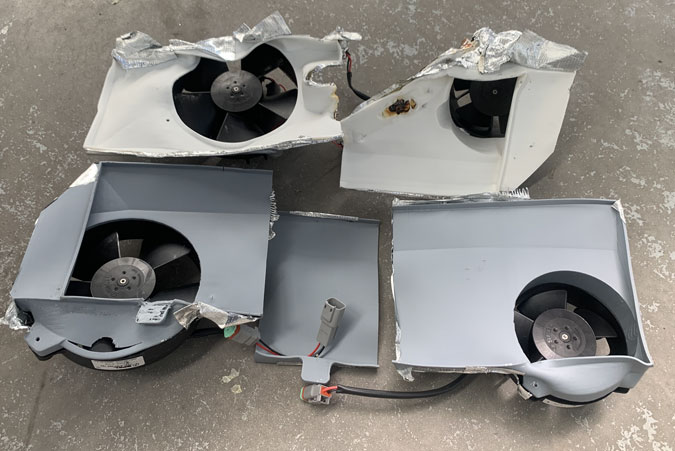
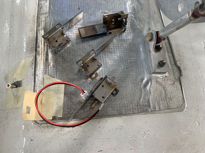
The four units are now assembled. Of course they weigh ‘something’ and I hate that but this problem needs solving.
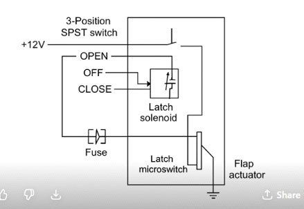
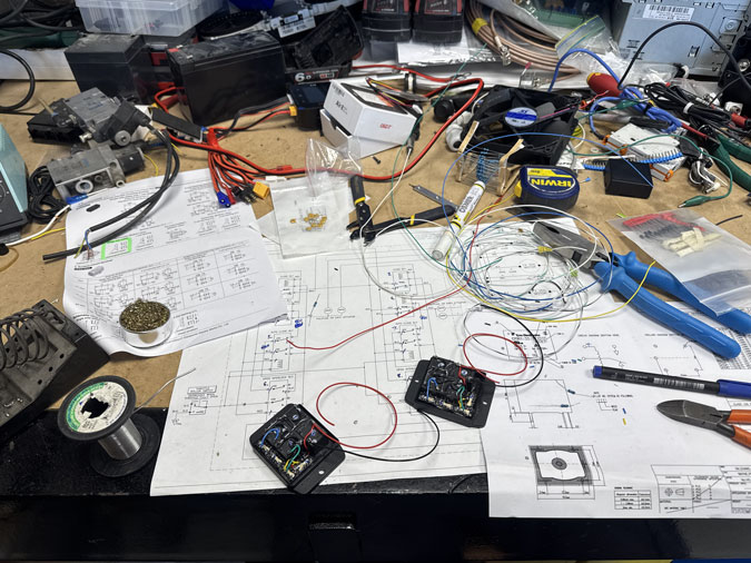
While discussing the ‘how’ with my electronics friend we wanted something that we could just wire into the cowls passively. No relays and no extra wires running to the cockpit. We are both a bit over that. The above is the ChatGPT solution which was a starting point for me to make some sort of contribution. It was what was already percolating in a better brain than mine. 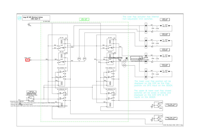
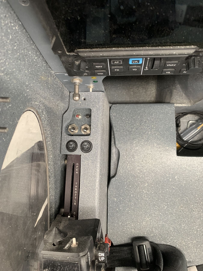
I tried to get it integrated into our existing, perfectly drawn circuit diagram but that was a big fail for the A.I. You can see a little mess in there three switches down. Maybe the next version will do it correctly. If anyone is crazy enough to do these flaps and needs the proper drawing, done by a smart human (not me!), just make contact and I’ll send the good copy along.
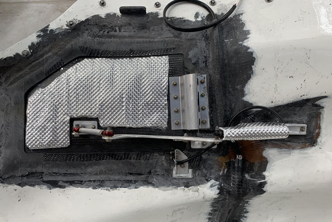
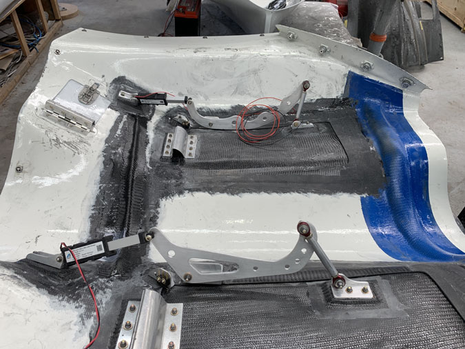
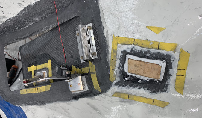
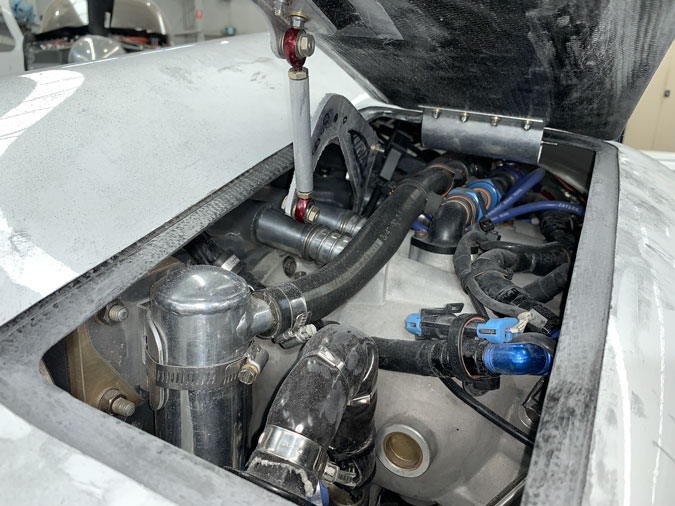
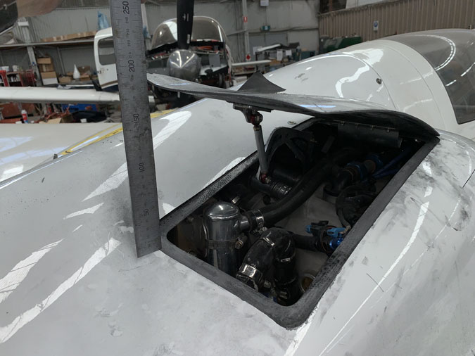
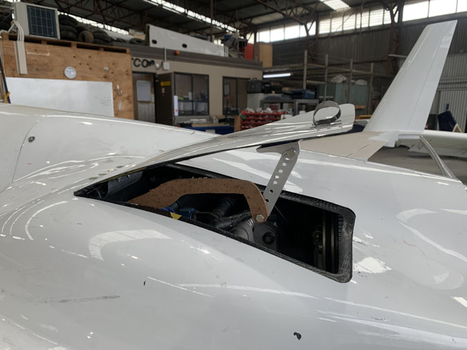
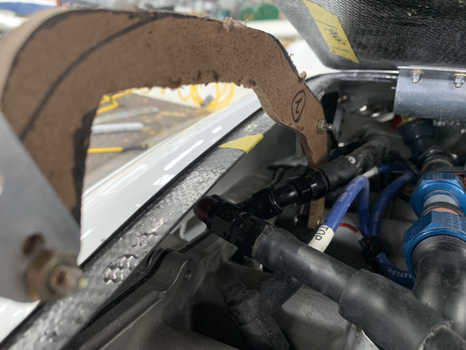
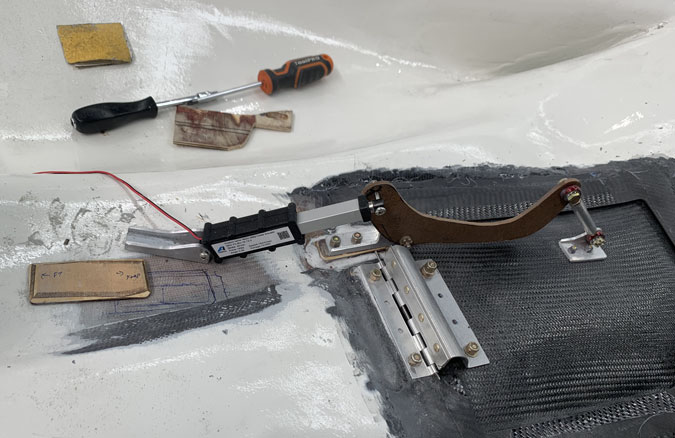
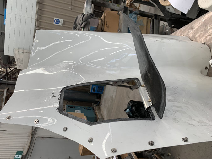
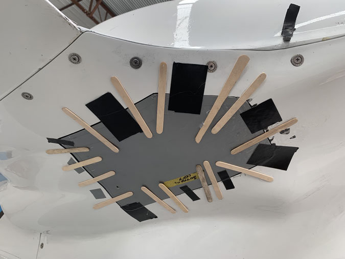
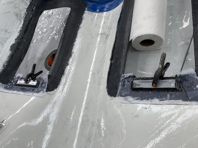
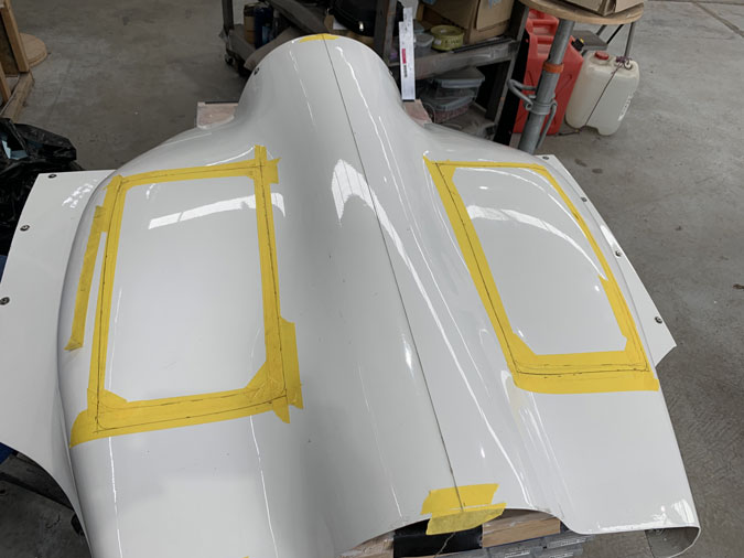
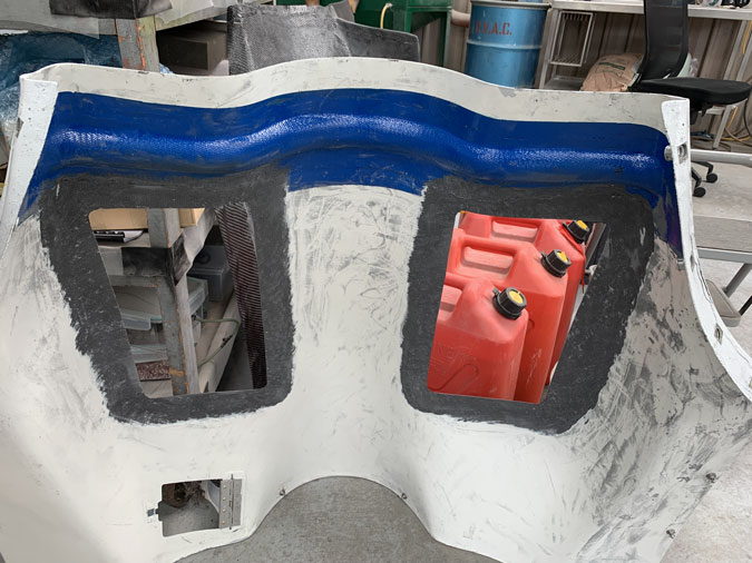
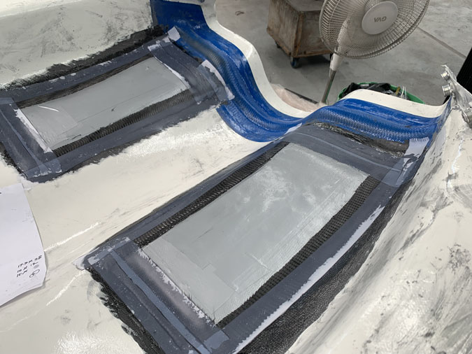
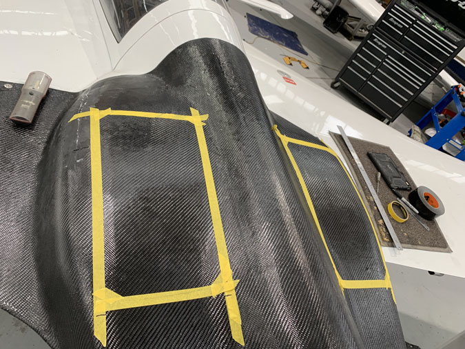
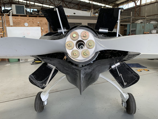
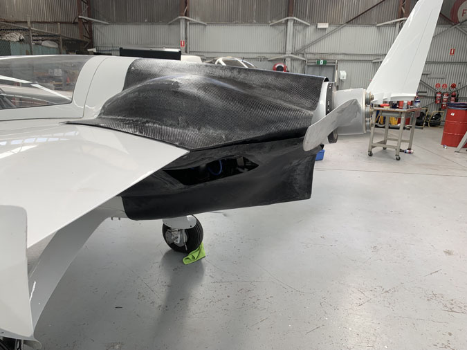
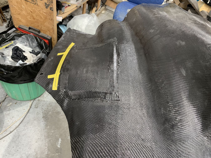
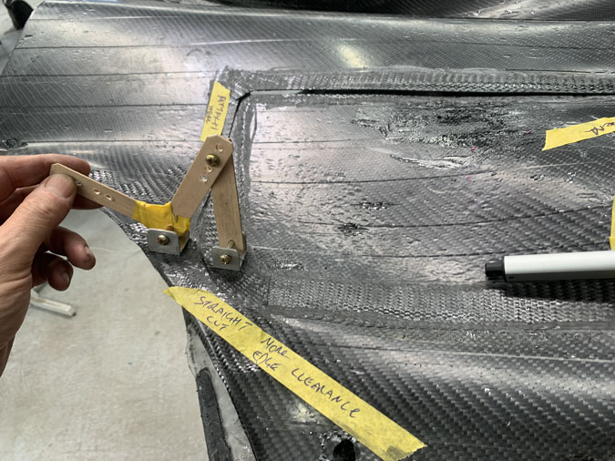
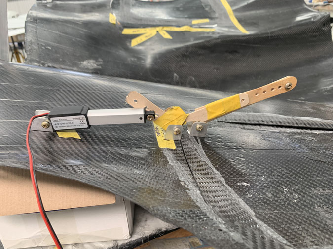
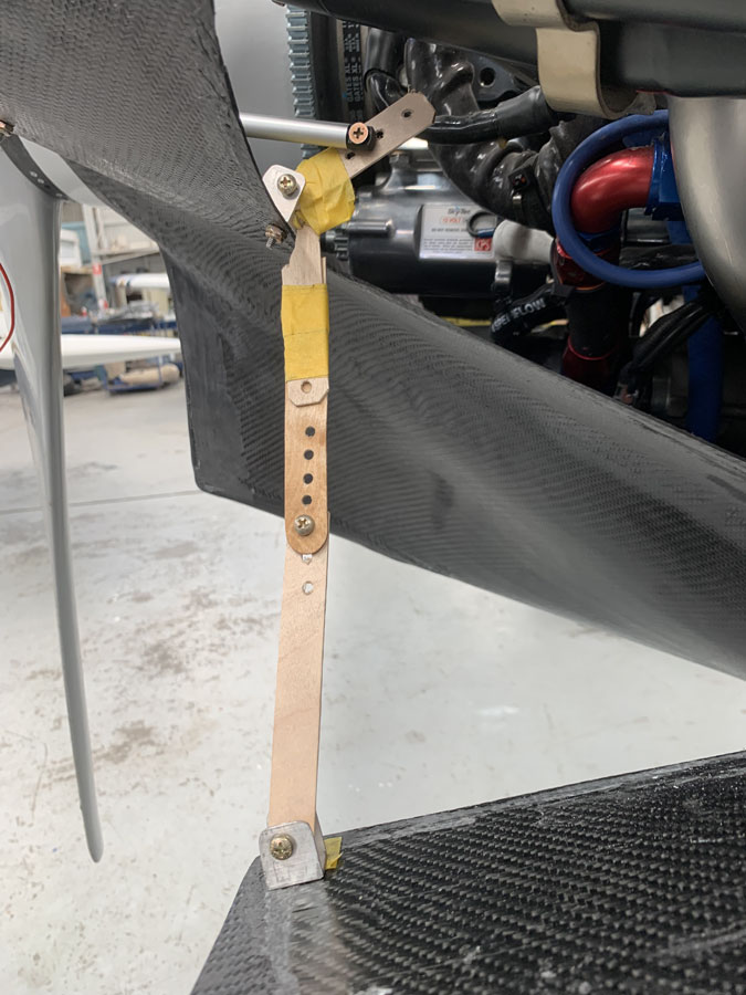
Next up we need to do the wiring. These are approximate spots for the latches. I’m not going to set it all up before the engine is back as there will no doubt be a gotcha and I’d have to move things an inch and make a big mess in the process. The striker plates or key holes can’t be done until then either. I suspect that each latch will need a different design depending on where and at what angle the unit sits.
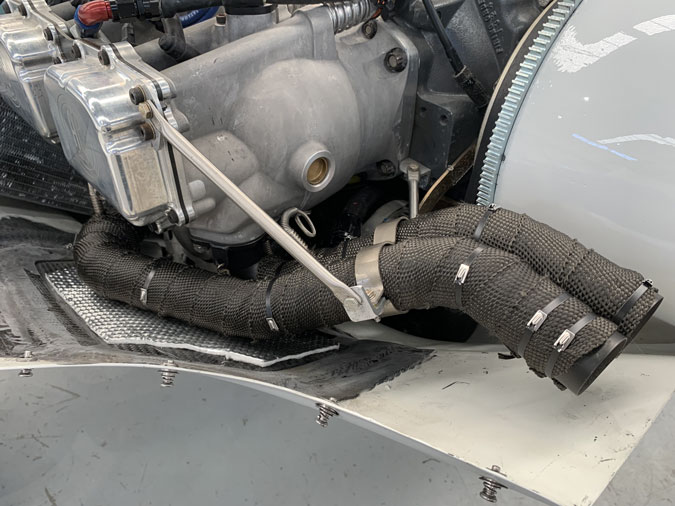
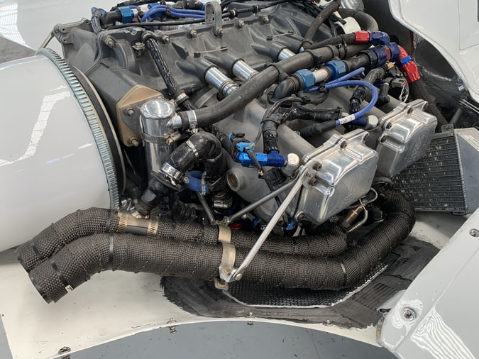
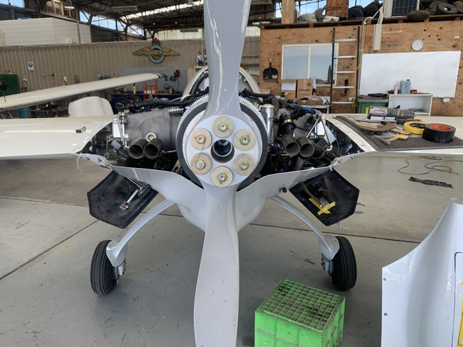
Well the engine is back, we are mid January 2026 now! I thought I should tackle this job so the cowls were ready before the engine was in case I had holdups. I did of course and I’d damaged one of the solenoids when fitting the cases, so more had to be ordered from Europe. <sigh>
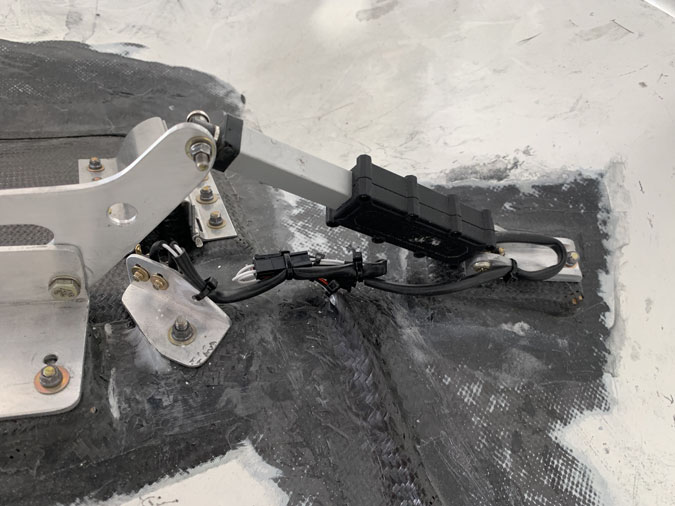
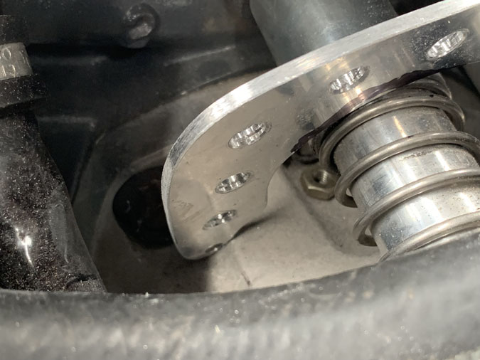
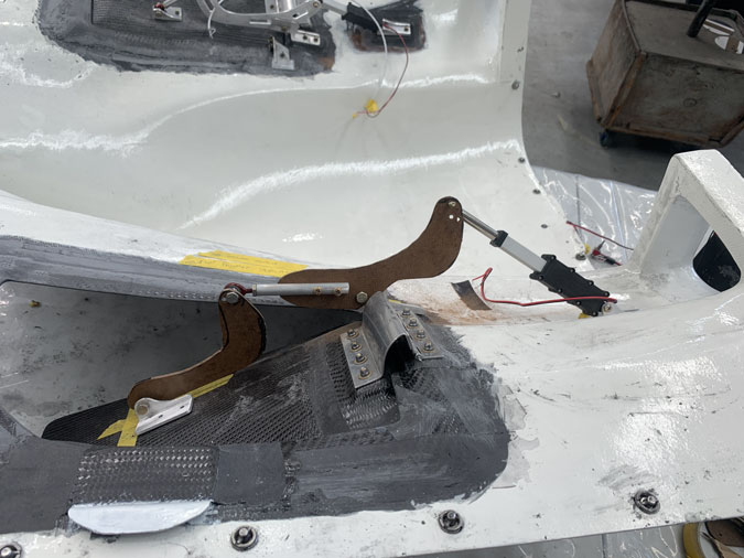
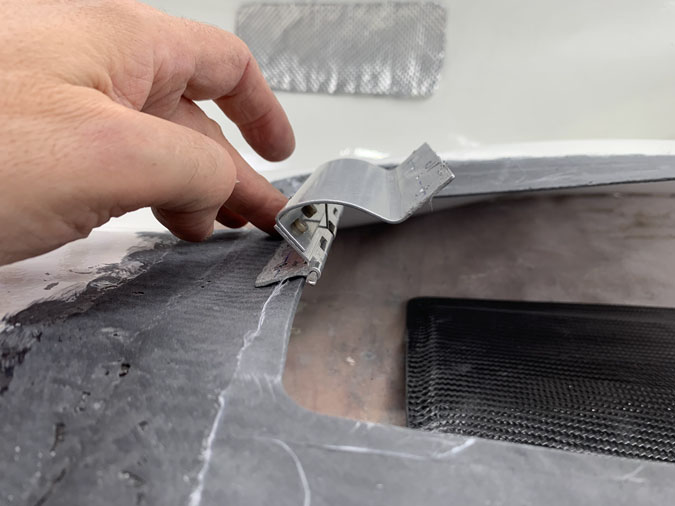
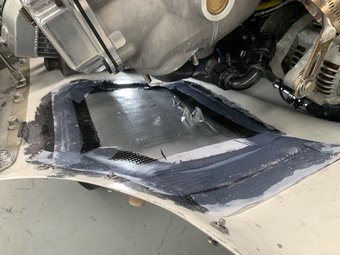
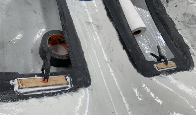
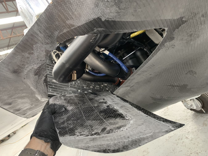
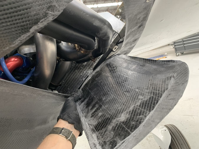
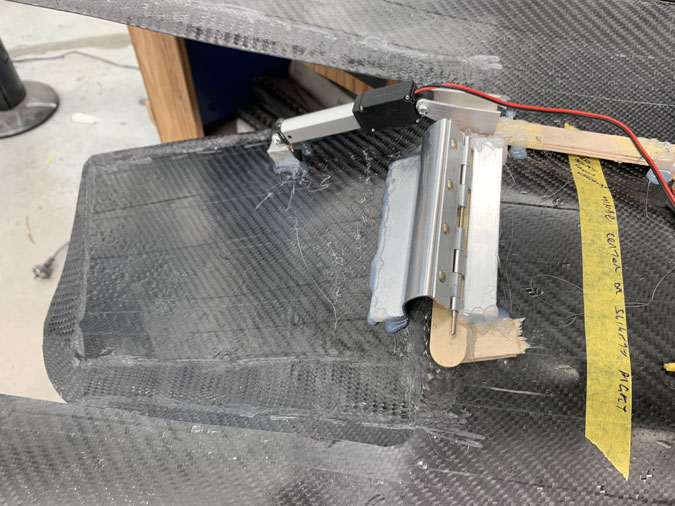
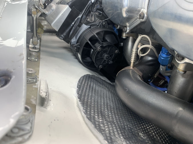
Each lock needed careful fitting. The latch ‘just’ catches as it also need to move out of the way for the flap to open. There is not a lot of movement in the small actuator for the tongue to pock out.
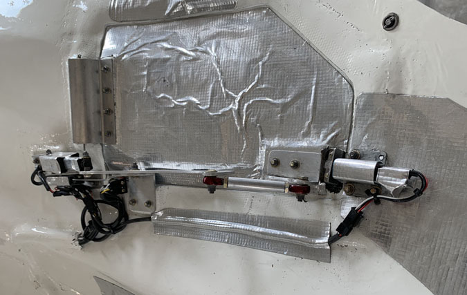
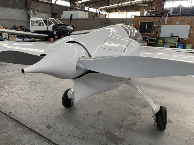
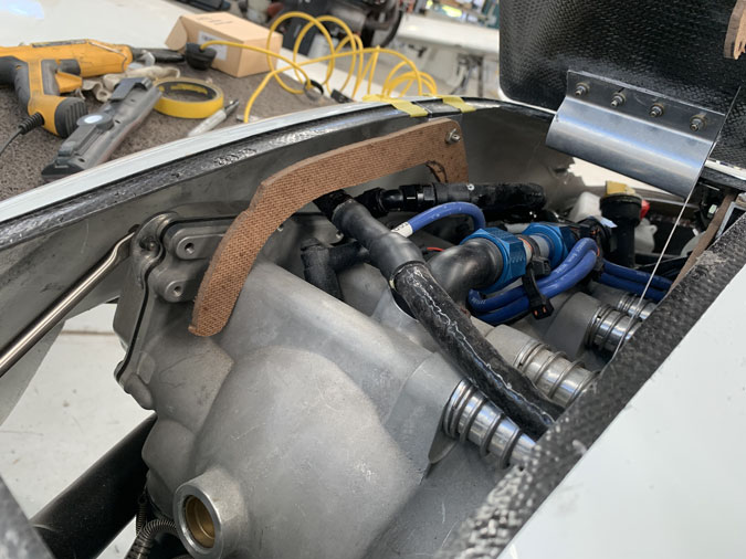
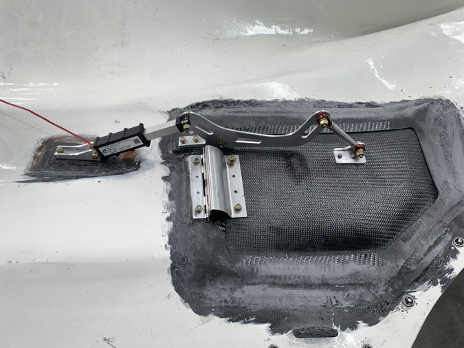
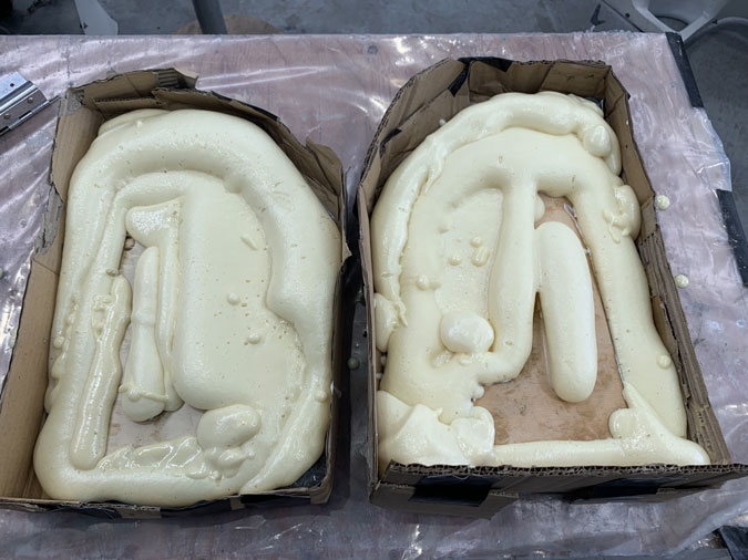
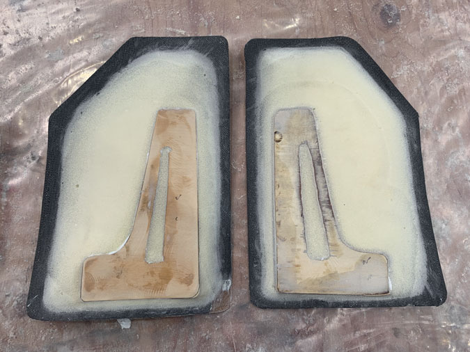
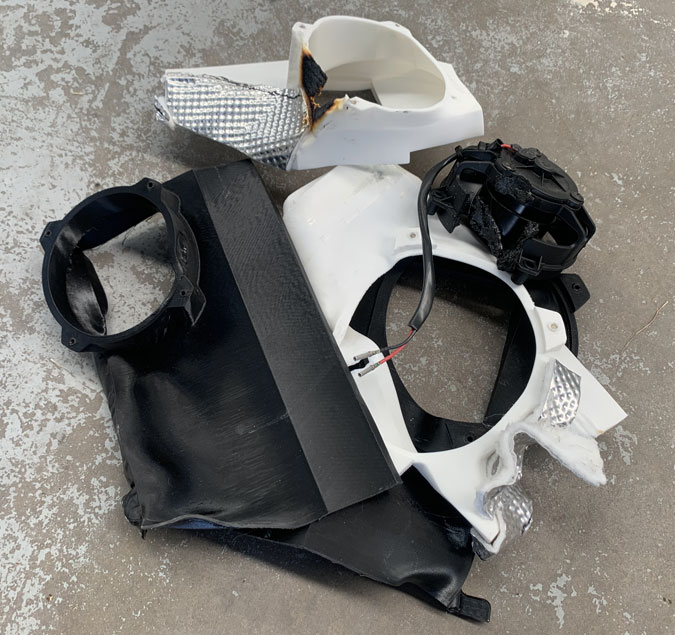
I have protected them from heat as best I can. Unfortunately the lock part has to position closer to the exhaust pipes than I like. We will see how they go.
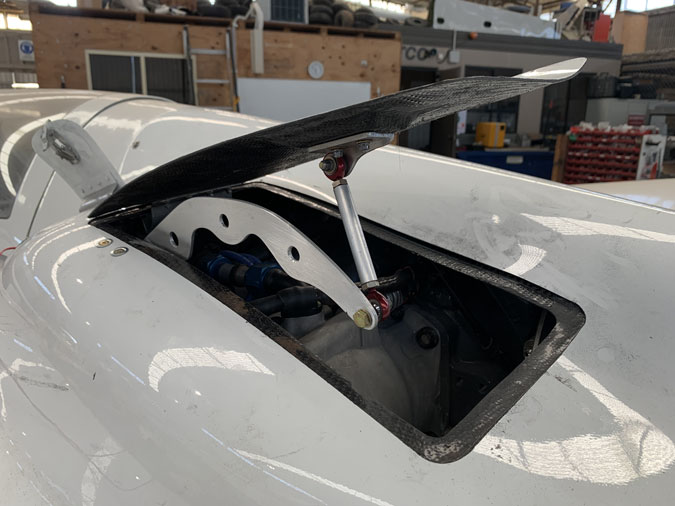
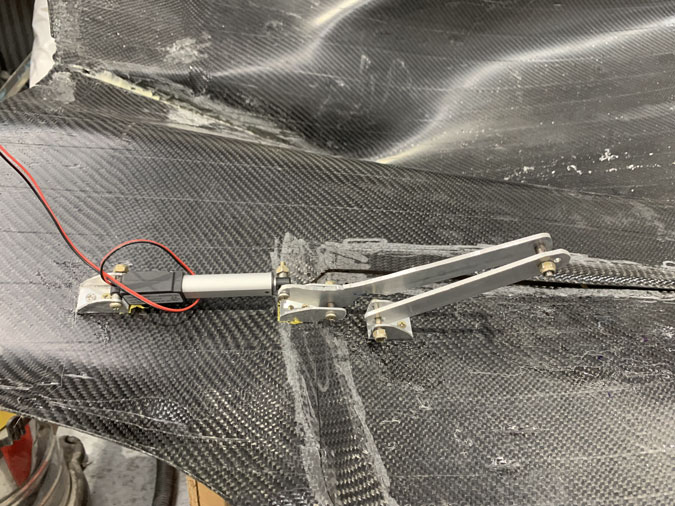
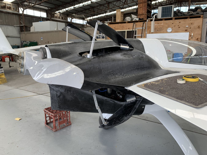
This is close to the final set up. It was as usual too much work and took too long. That’s just the nature of this project and when doing something a little different.
This is a low res version but still a bit big for a website video. It does give you a look at the flaps in operation.
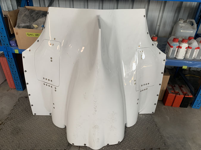
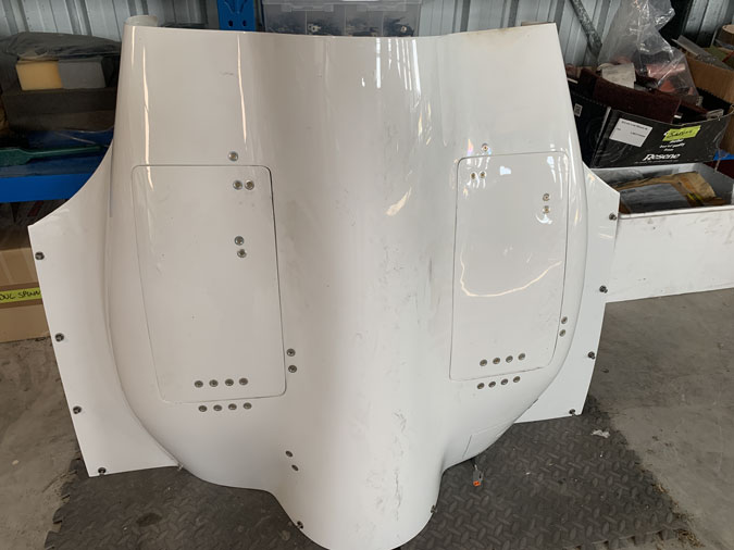
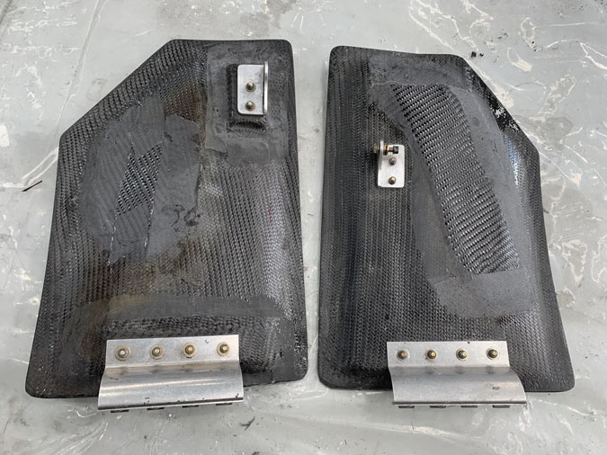
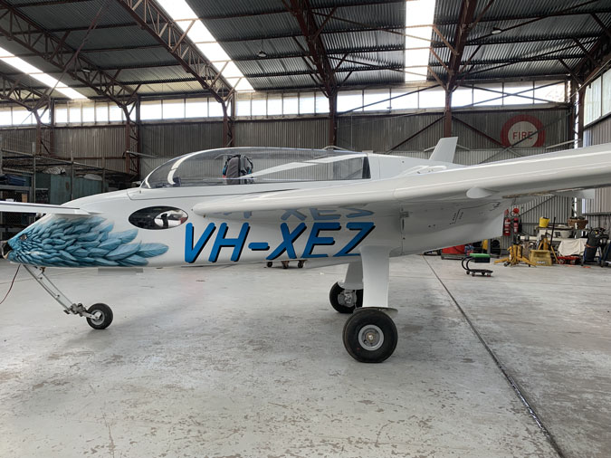
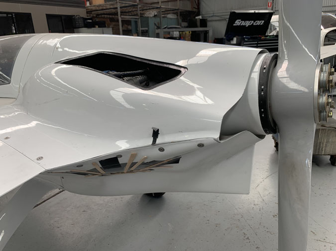
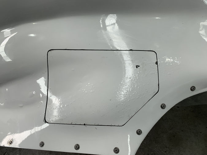
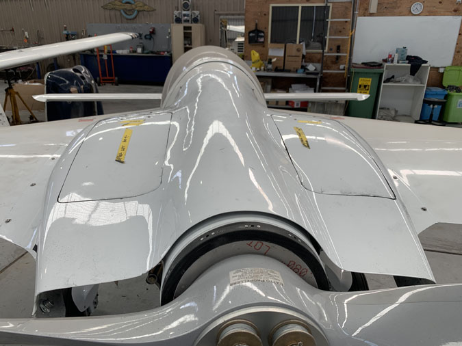
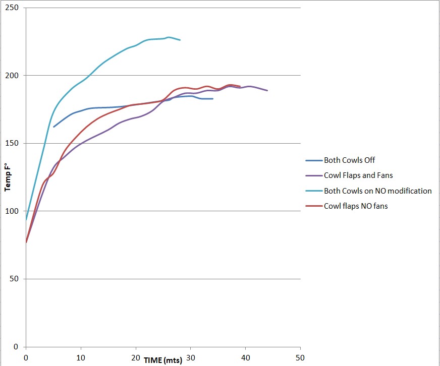
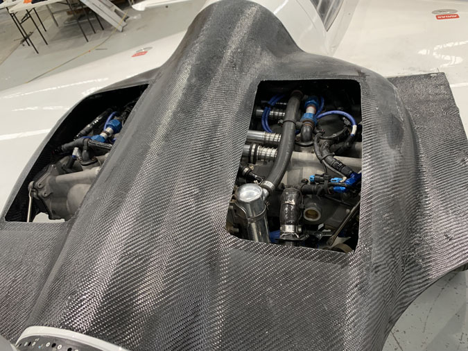
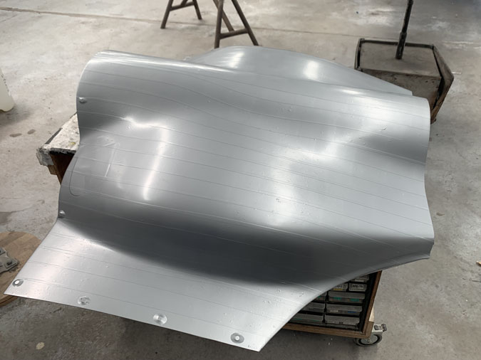
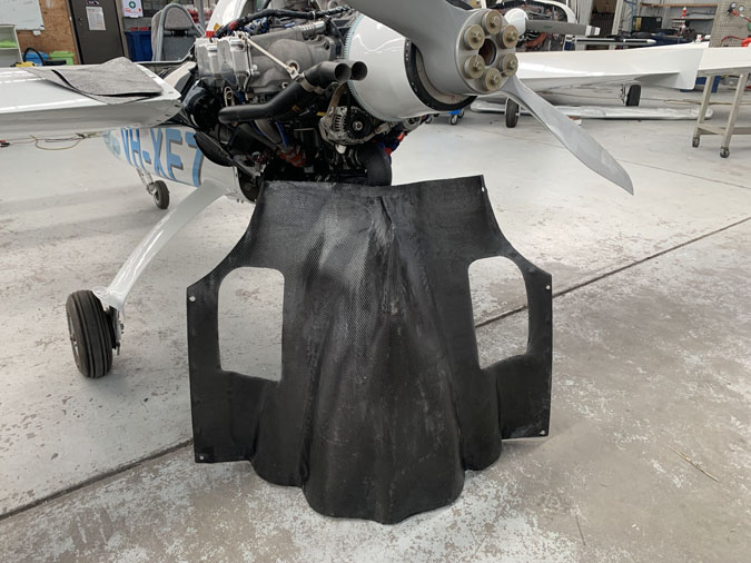
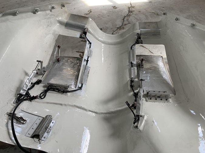
Just to show you… there are now a LOT of fasteners on these cowls and I had to add a lot of weight. I’m not happy about this side of the work but I do think the ground cooling problem is solved and hopefully the in air cracking open of the flaps as well. Fight testing will tell the story.