| Date: 09-07-2017 | |
| Number of Hours: 2 | |
| Manual Reference: no ref |
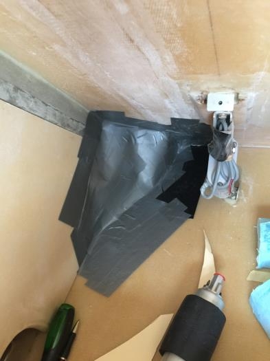
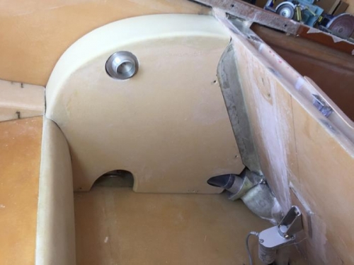
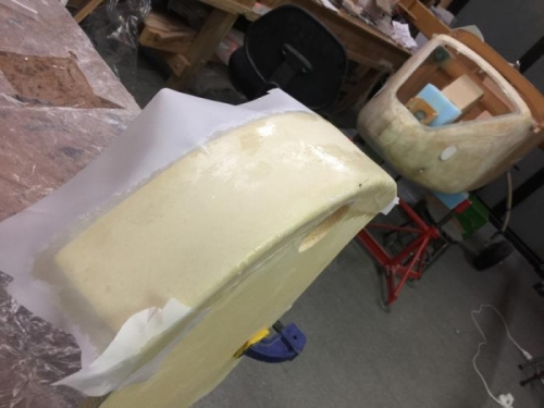
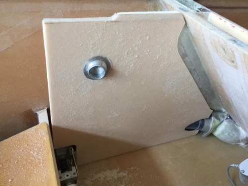
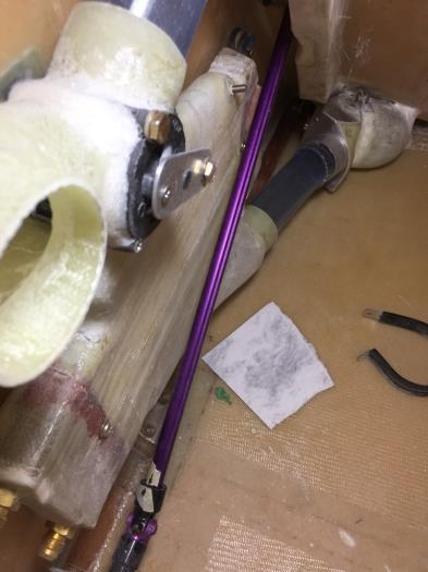
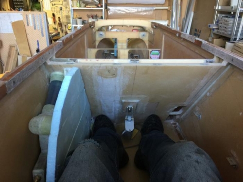
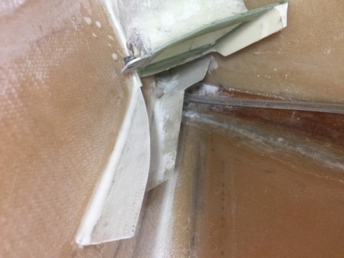
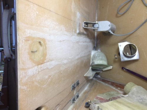
What are the chances of being about .25″ out for fitting the exit hoses from the Heat Exchanger? Pretty high possibility hahaha.
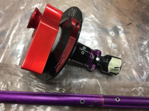
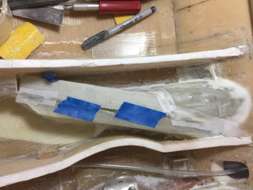
I elected to go -10 hoses here to get a better oil flow. I’m using SpeedFlow 101-10 and a fitting that goes from -6 to -10 on the radiator. It was just a little above the armrest core but not above the top.
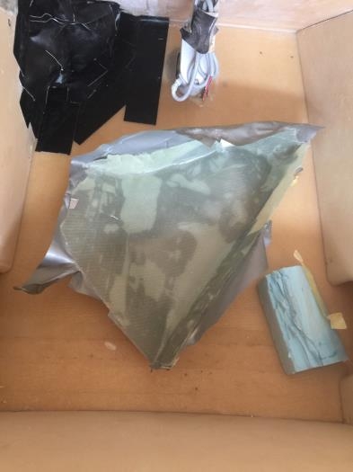
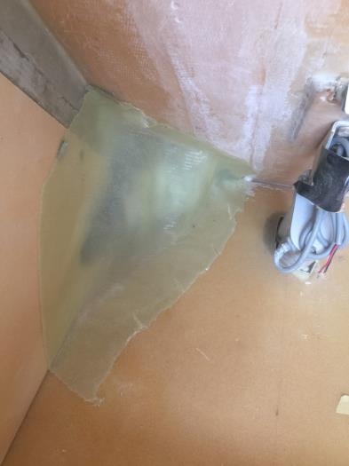
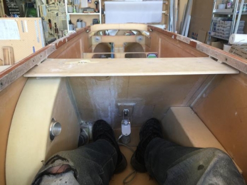
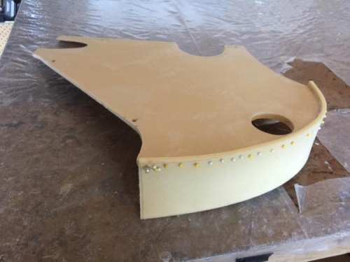
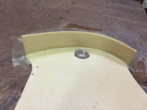
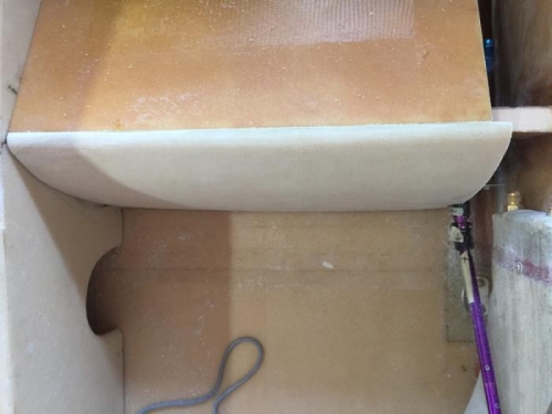
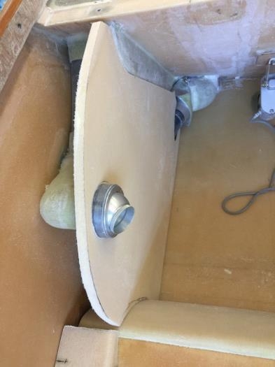
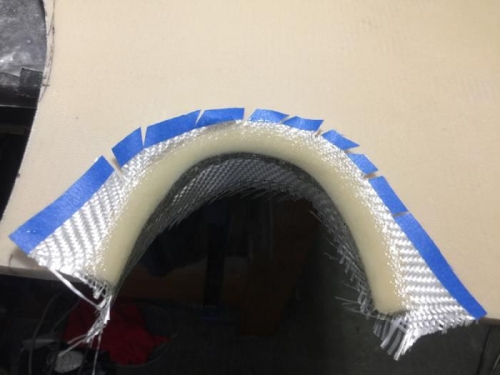
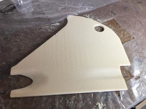
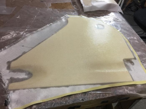
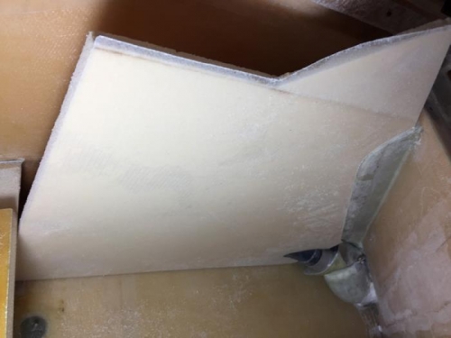
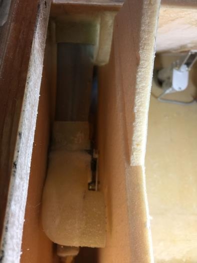
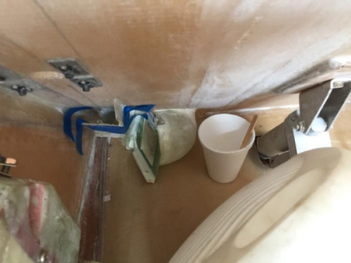
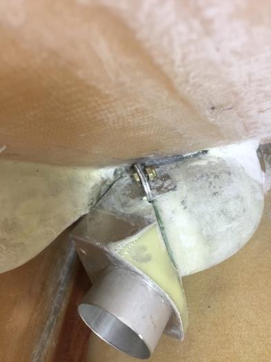
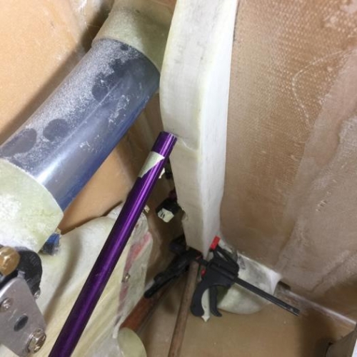
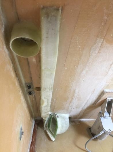
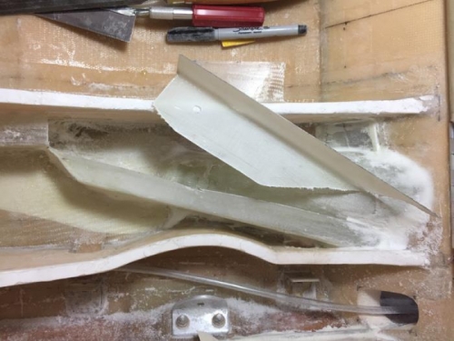
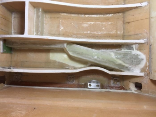
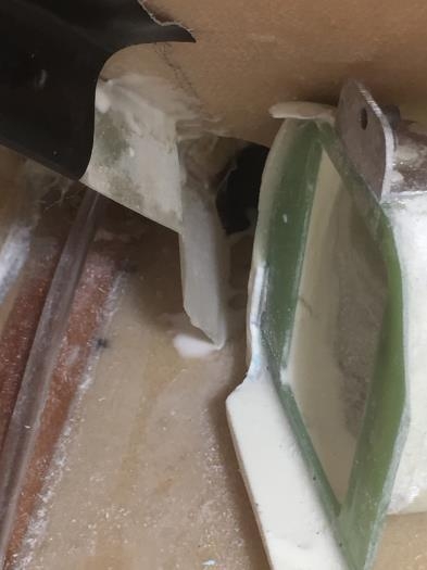
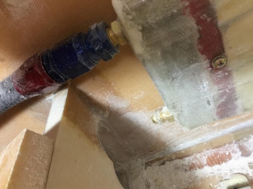
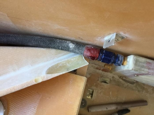
My fix was to cut some foam away, make a concave glass insert, clean it all up as you see in pic 2. Pic 3 and we have a fit.
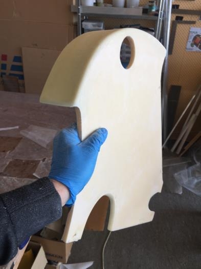
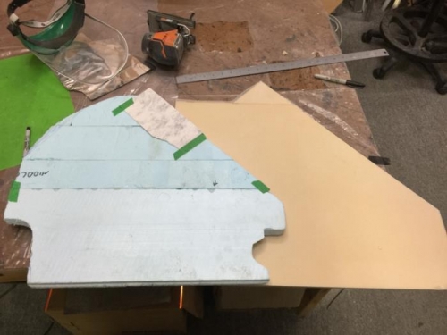
A small job but typical for this part of my build.
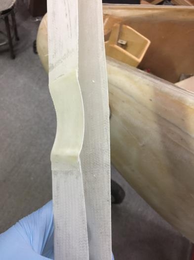
Not quite a fit
Adjustments
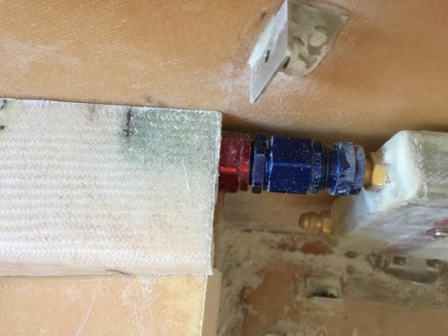
Just makes it