• Home
  • Flying
    • First Flight
  • Build by Chapter
    • Ch 3 Education
    • Ch 4 Fuselage Bulkheads
    • Ch 5 Fuselage Sides
    • Ch 6 Fuselage Assembly
    • Ch 7 Fuselage Exterior
    • Ch 8 Roll Over/Seat Belts
    • Ch 9 Main Gear/Landing Brake
    • Ch 10 Canard
    • Ch 11 Elevators
    • Ch 12 Canard Installation
    • Ch 13 Nose and Nose Gear
    • Ch 14 CenterSection Spar
    • Ch 15 Firewall and Accessories
    • Ch 16 Control System
    • Ch 17 Roll/Pitch Trim System
    • Ch 18 Canopy
    • Ch 19 Wings, Alierons
    • Ch 20 Winglets/Rudders
    • Ch 21 Strakes – Fuel/Baggage
    • Ch 22 Electrical System
    • Ch 23 Engine Installation
    • Ch 24 Covers/Consoles
    • Ch 25 Finishing
    • Ch 26 Upholstry
  • Build Mods
    • Liquid Cooling, Numbers, Weights and Flow
    • Cooling
      • Solving Ground Cooling 1
      • Solving Ground Cooling 2
      • Solving Ground Cooling 3
      • Solving Ground Cooling 4
      • Solving Ground Cooling 5
      • Solving Ground Cooling 6
      • Solving Ground Cooling7 – Test Data
      • Solving Ground Cooling 8 – Flap Building
      • Solving Ground Cooling 9 – Hinges
      • Solving Ground Cooling 10 – Lower Flaps
      • Solving Ground Cooling 11 – Upper Flaps
      • Solving Ground Cooling 12 – Completed
      • Cooling the Beast 1
      • Cooling the Beast 2 – Lower Cowl Expansion
      • Cooling the Beast 3 – KW Oil Cooler Diffuser
    • EVS (Enhanced Vision System)
    • Cowl Keeper
    • Rudder Gust Locks
    • Wing Fences
    • Post Cure
    • Hinge Upgrade
    • RAM Air & Hellhole Cover
    • Main Gear Beef Up
    • Pilot Side Windows
    • Baggage Pods
    • Winglet Intersection Fairings
    • Titanium Rollover
    • Nose Gear Doors
    • Wheel Pants/Gear Leg Fairing
    • Cabin heating System
    • Fuel System
    • Roll and Pitch Trim
    • Oxygen System
    • The Ferry Tank
    • Cruise Angle Indicator
    • Fire Extinguisher Install
  • Round the World
    • RTW Route East #12 rev1
    • Survival Equipment
    • Training Flights
  • Other Stuff
    • Blog
    • Around the World: RAAUS Sport Pilot Issue 110
    • Taxi Tests
    • Summary Feb ’24 from an SAAA Meeting
    • AOPA Pilot 27th Sept 2019
    • Build Tests
    • Flying Stories
      • A Long Easy Dream ’06
      • Townsville ’07
      • Cairns ’08
      • Albany ’08
      • East Coast ’08
      • Brisbane ’09
      • Cairns ’10
      • Perth ’10
    • Non Build Mods
      • F16 Scoop for JZE
      • Ram Air Box for JZE
      • Strange Tips
    • Milestones
    • Links
  • Contact

Baggage Pods

Home
Build Mods
Baggage Pods

Pod Filler

Date:  02-26-2019
Number of Hours:  12
Manual Reference:  no ref

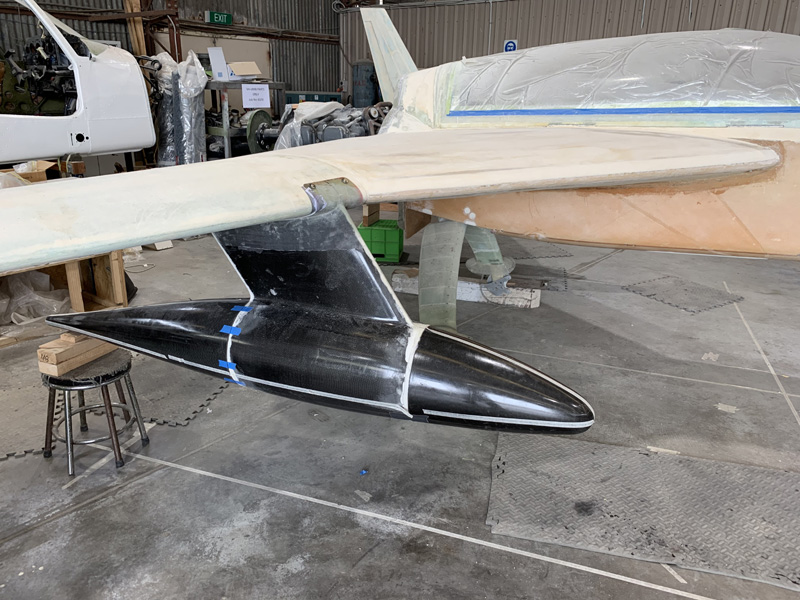
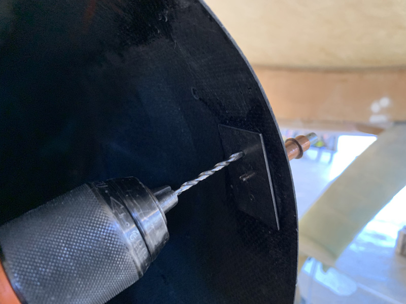
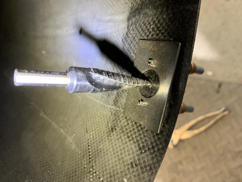
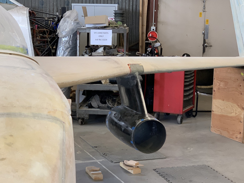
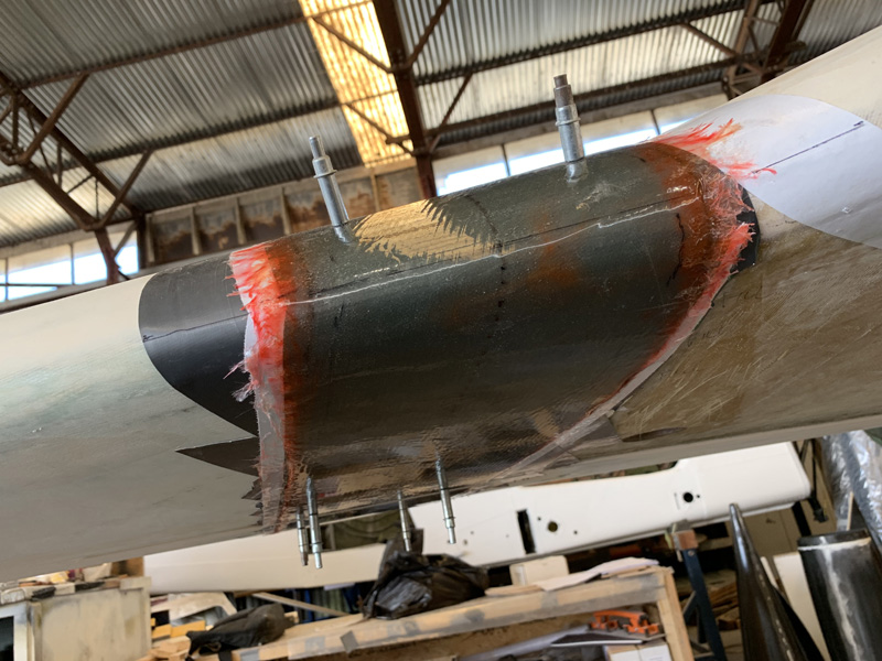
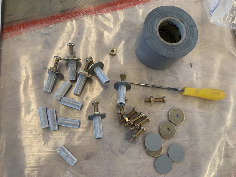
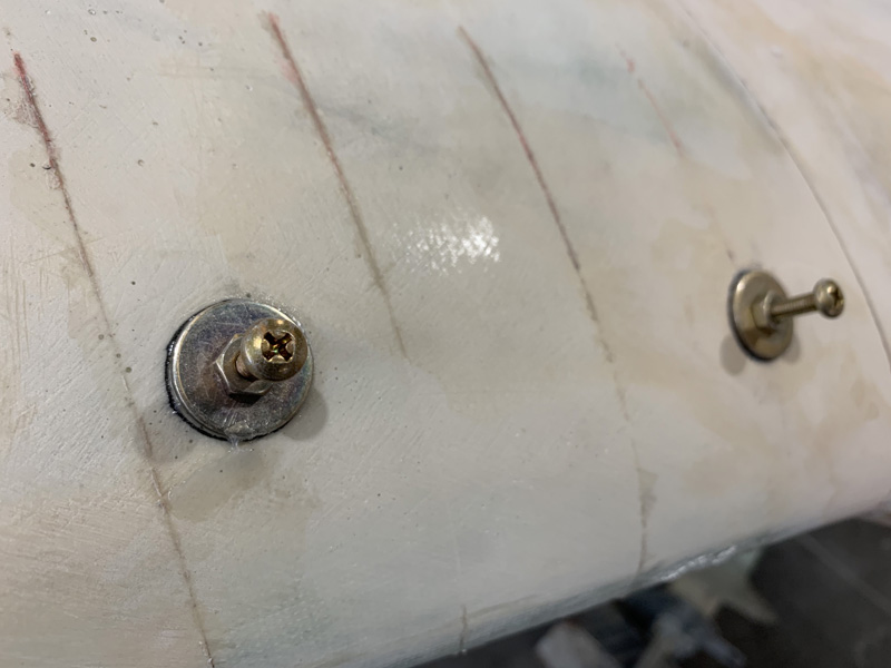
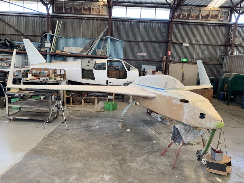
With the fasteners finally in some refining of the joins and fill is required.

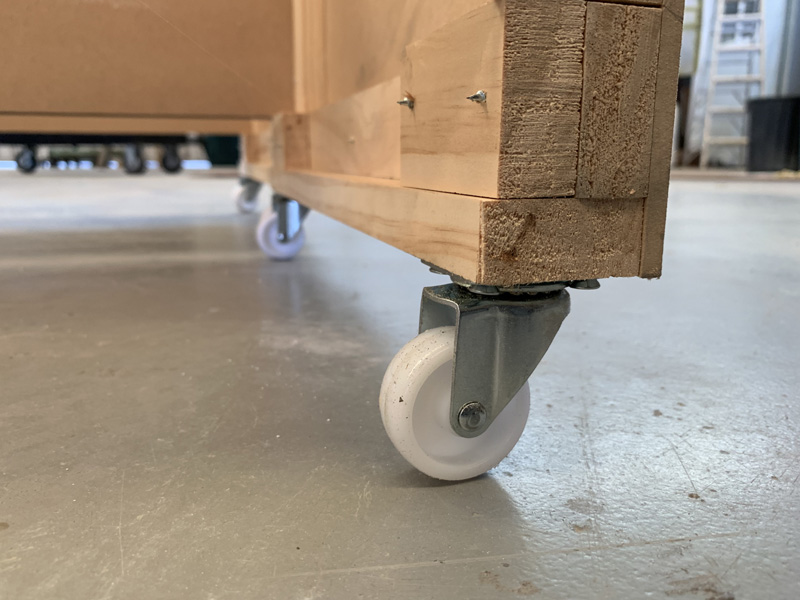
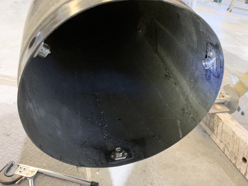
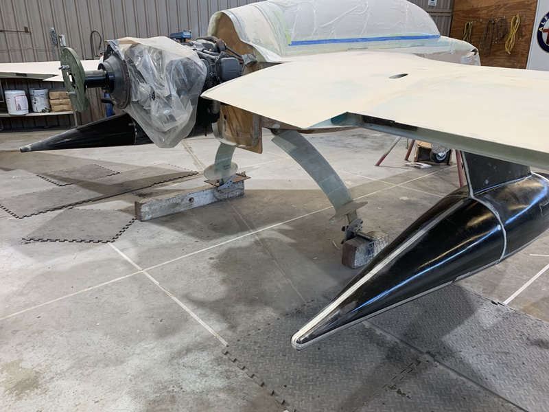
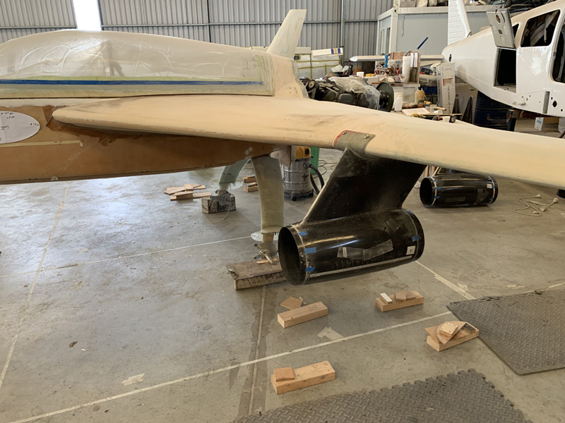
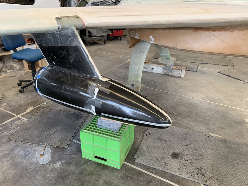
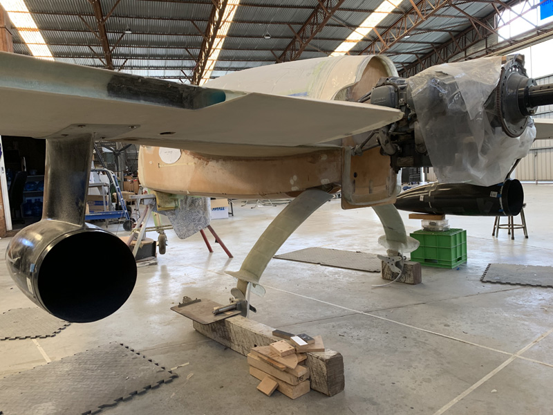
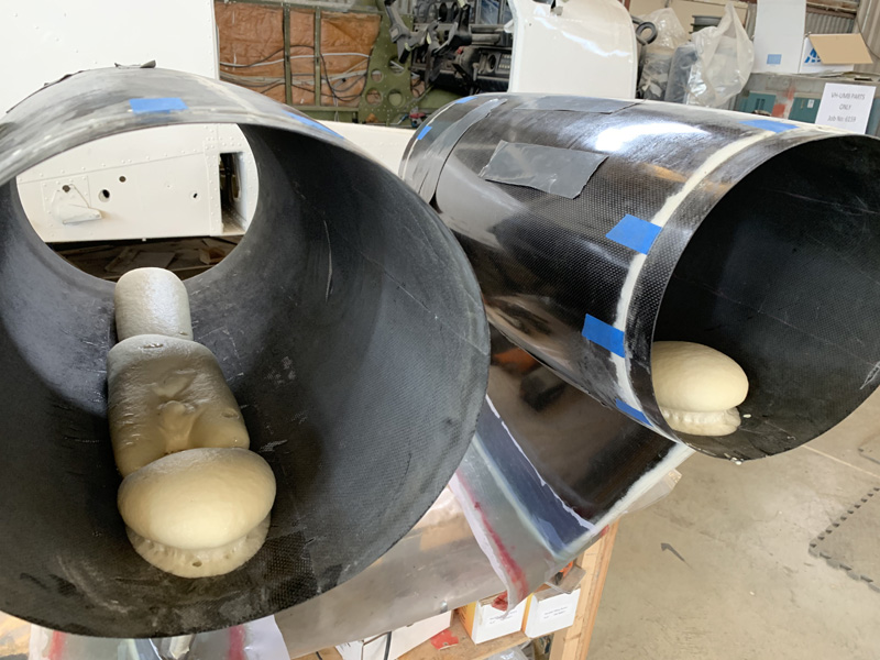
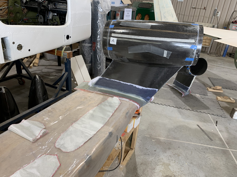
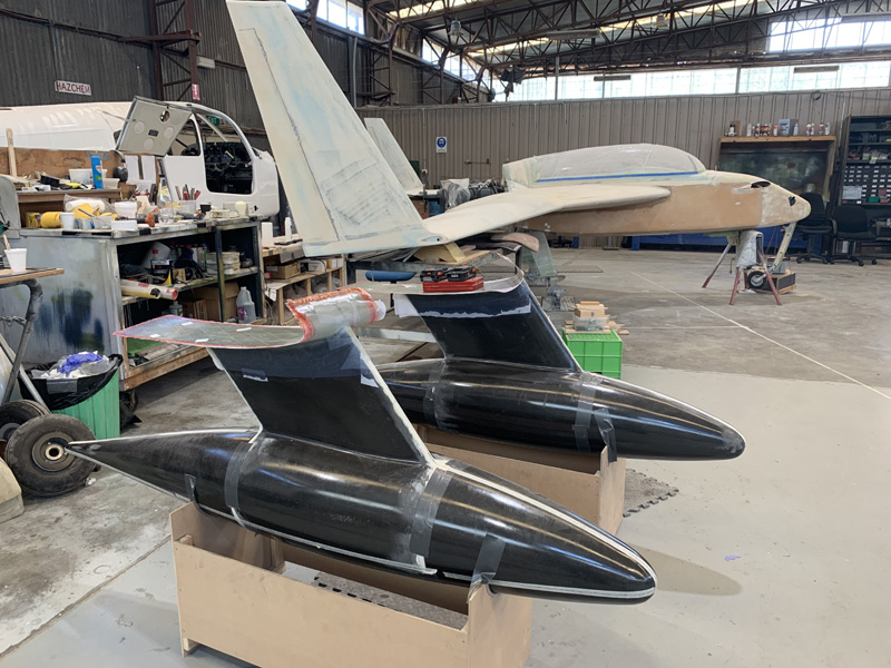
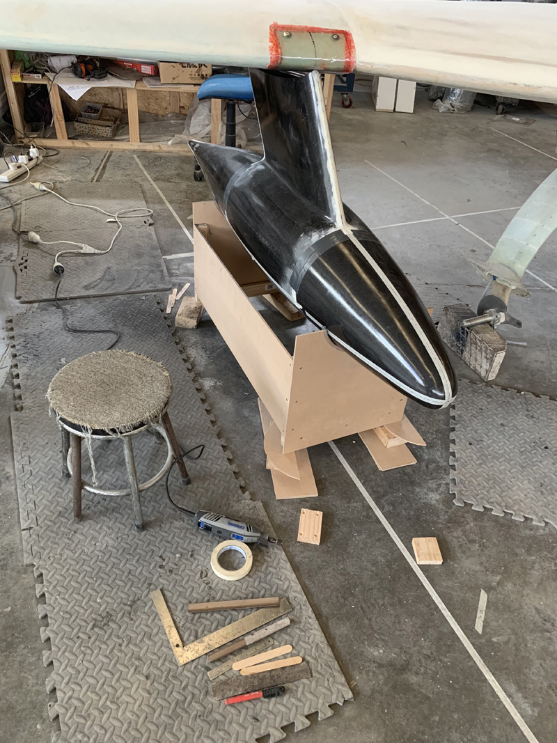
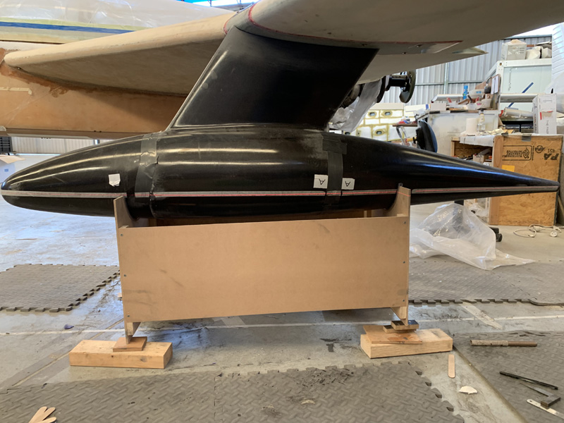
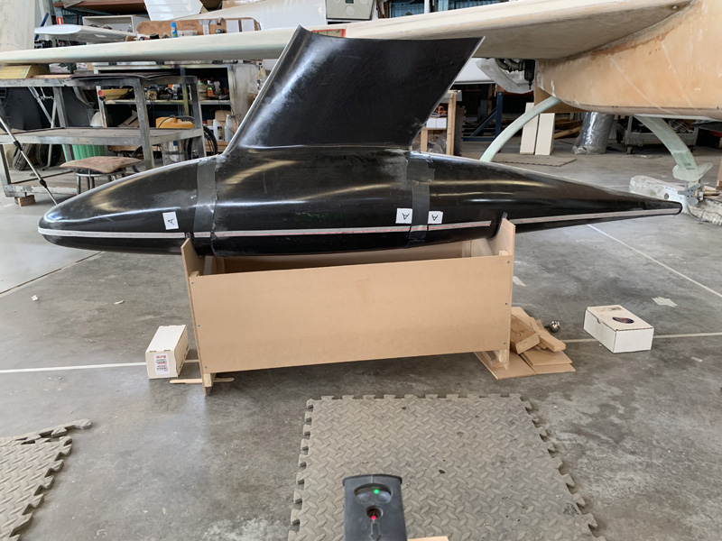
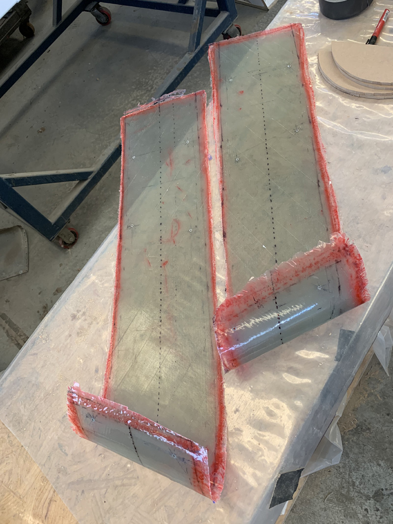
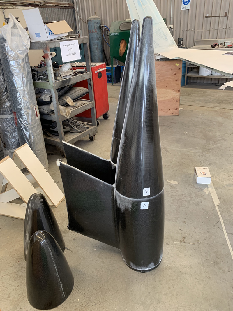
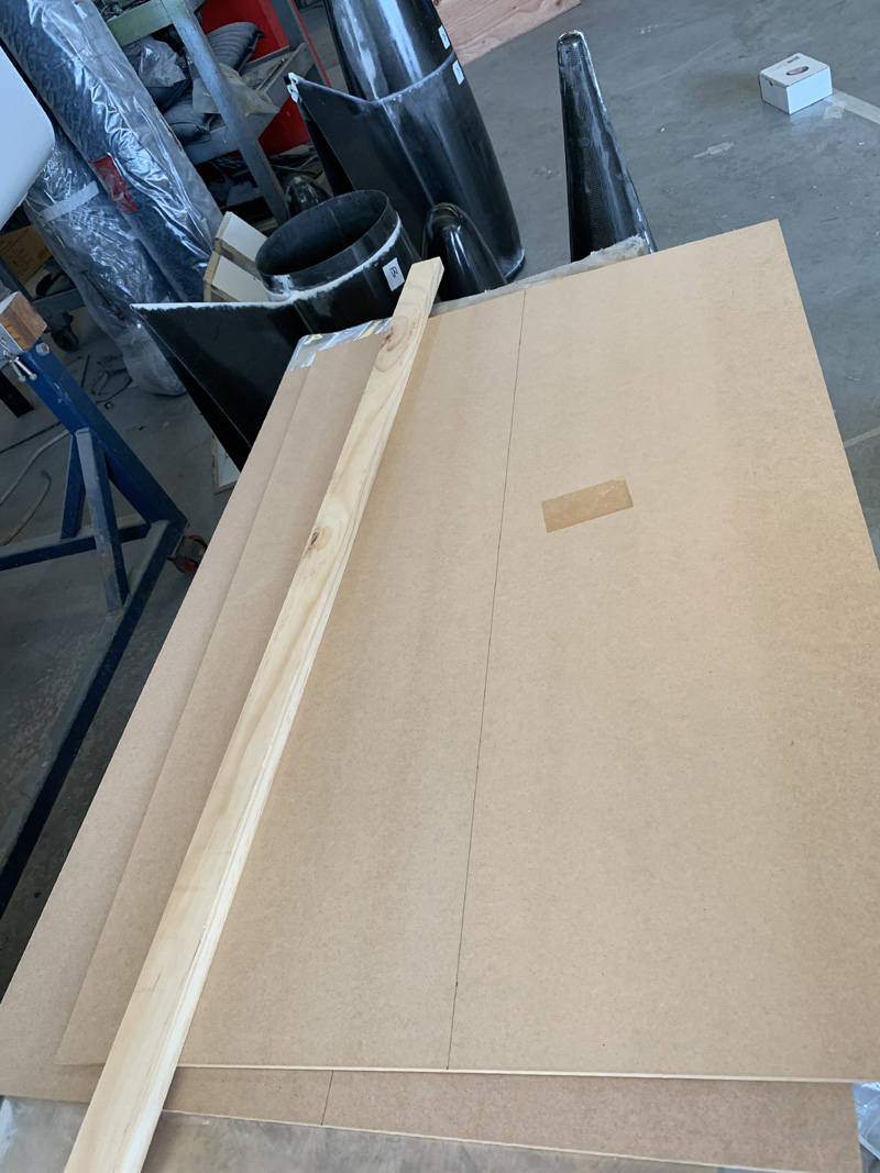
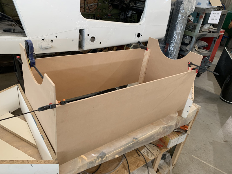
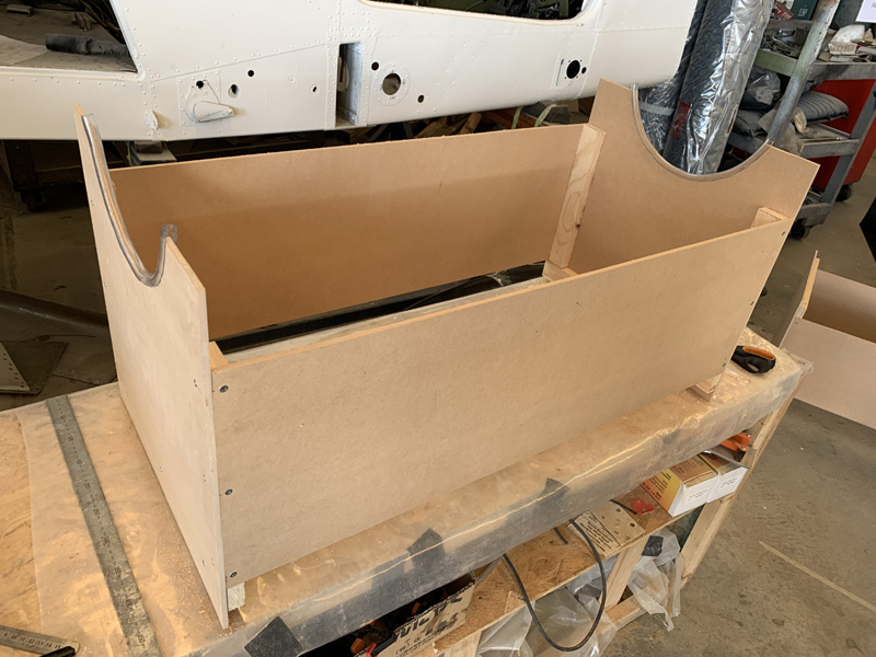
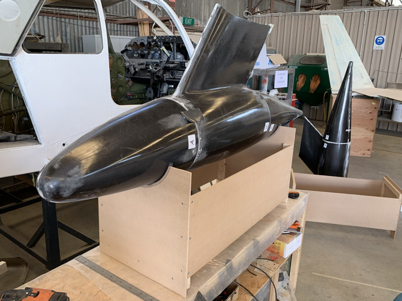
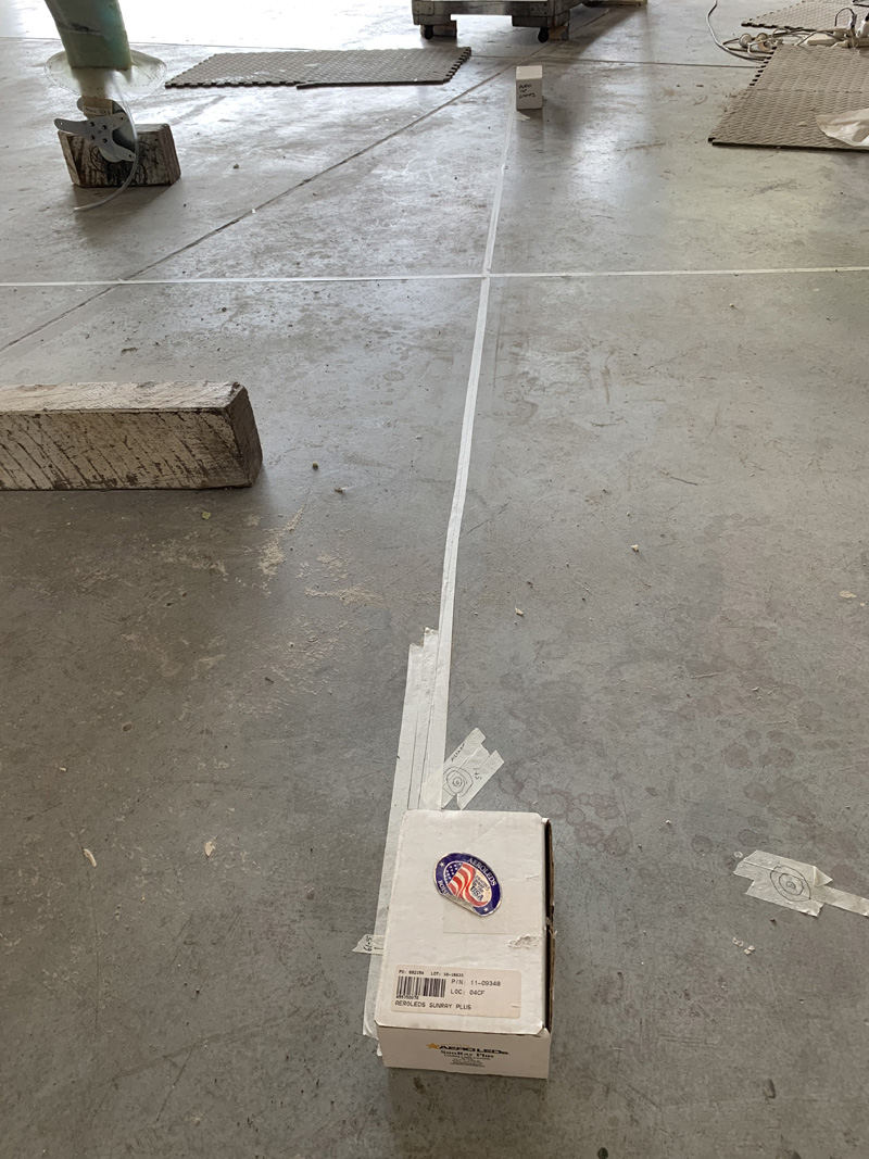
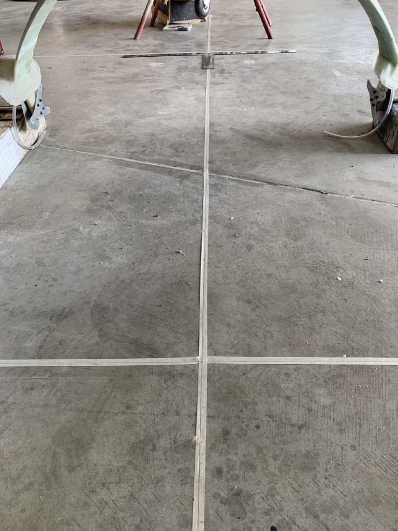
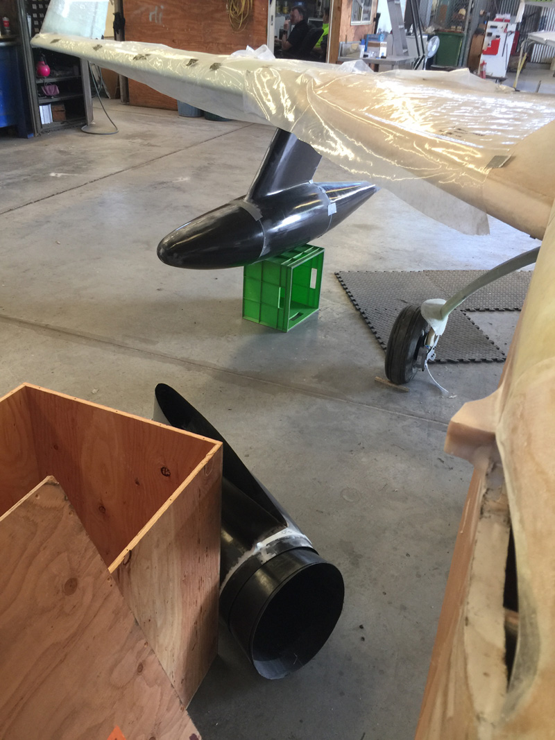
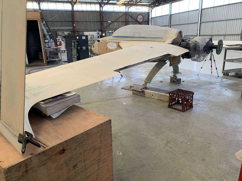
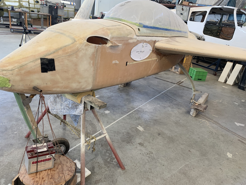
First up was to reinforce the pod carriers and add wheels.

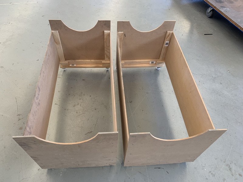
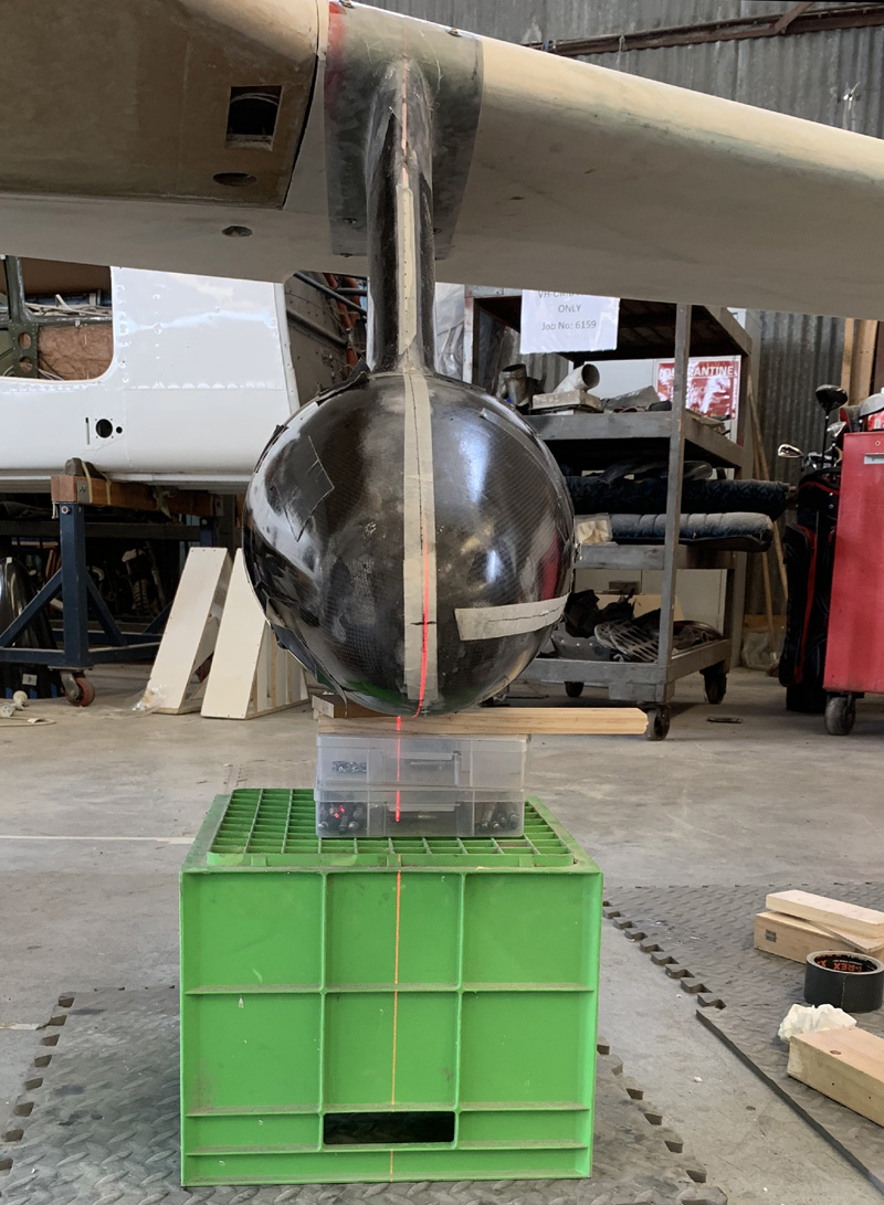
A couple of hours later and I can see these being used for a number of years while the pods are off the plane.

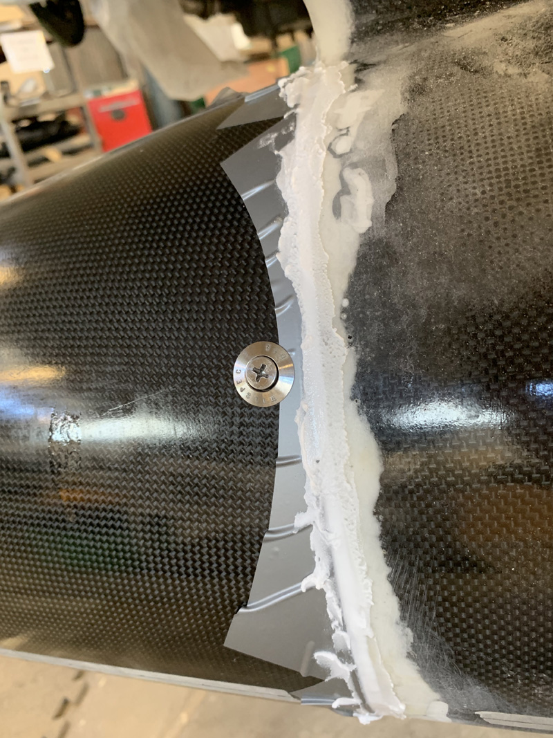
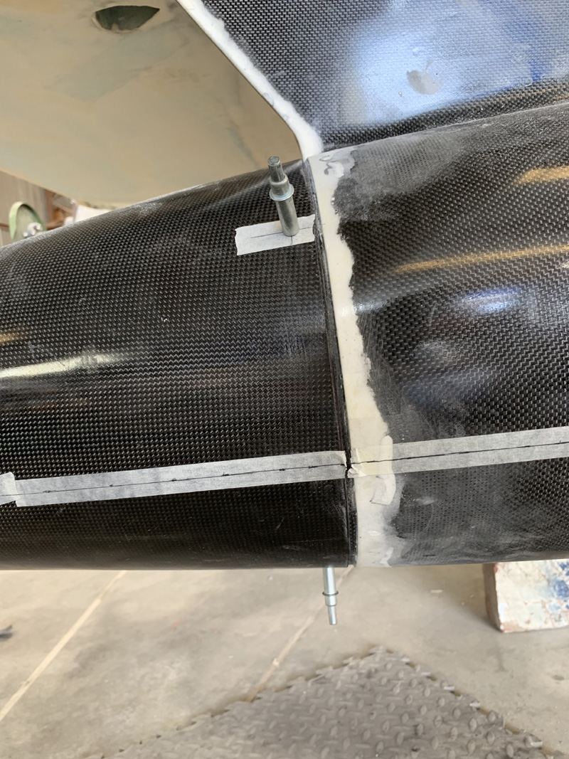
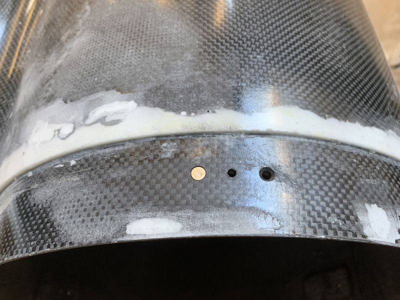
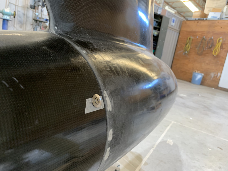
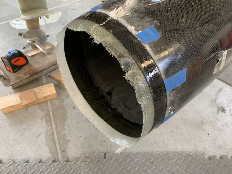
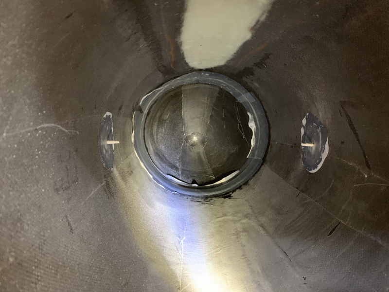
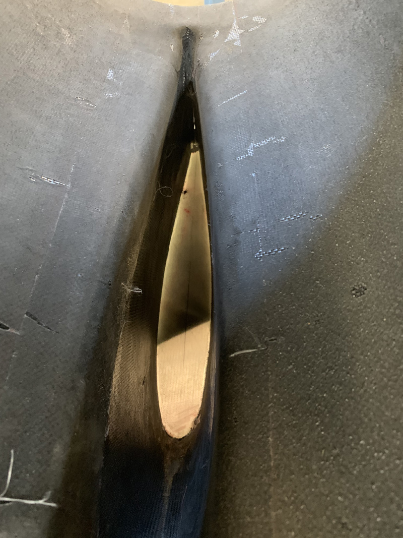
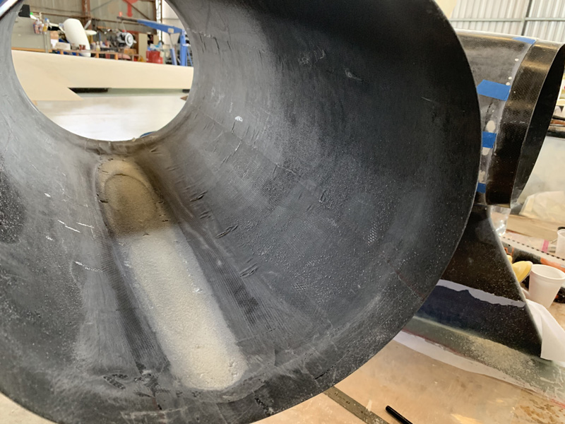
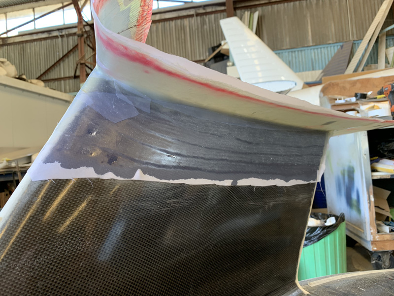
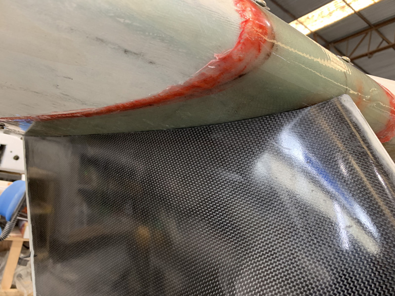
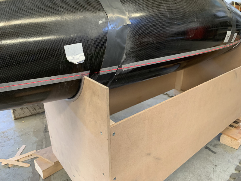
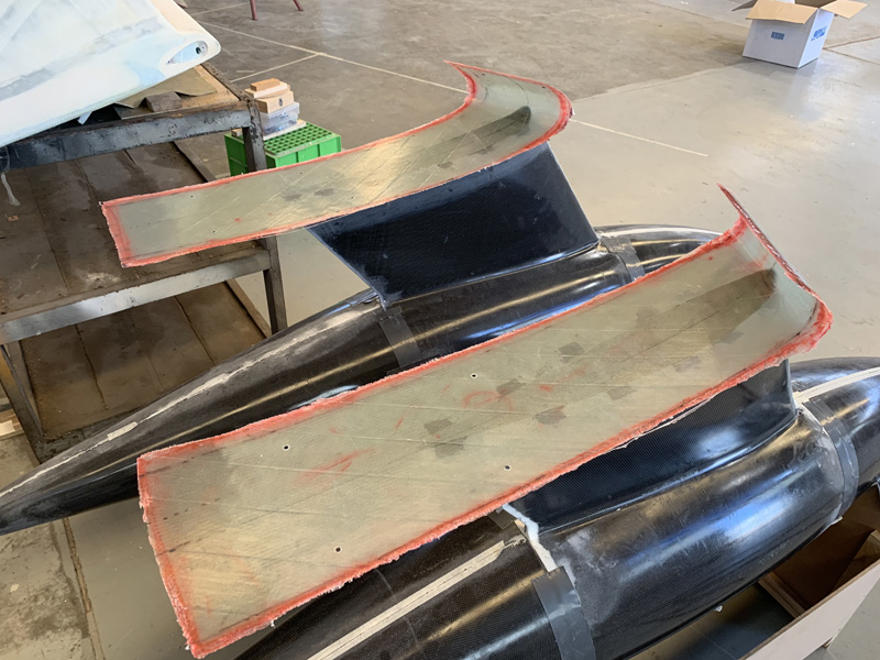
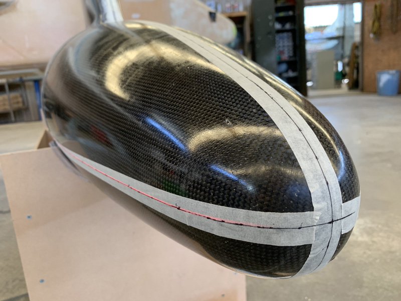
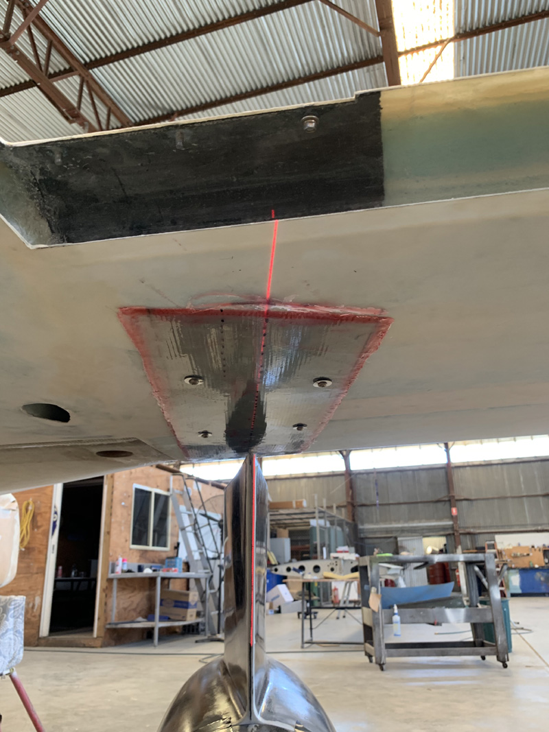
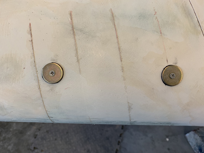
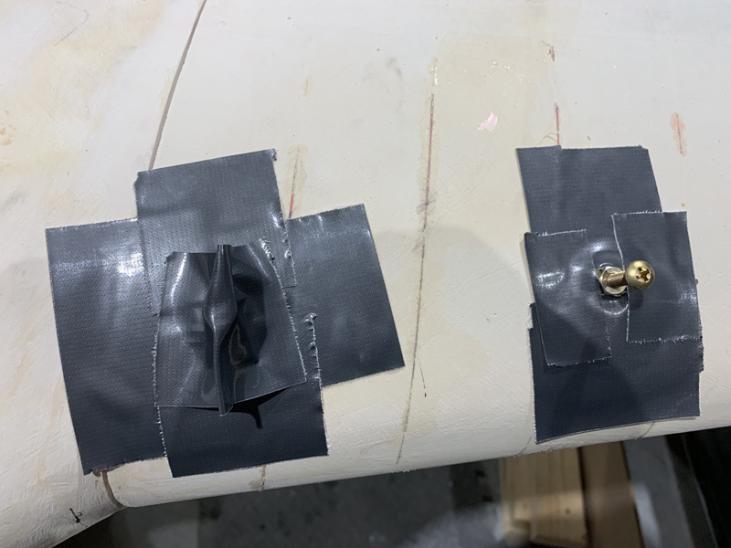
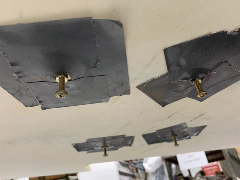
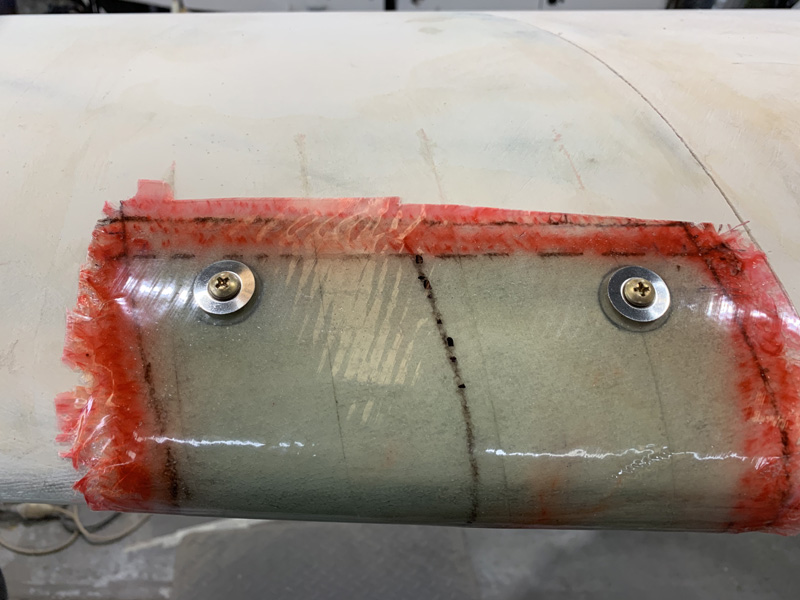
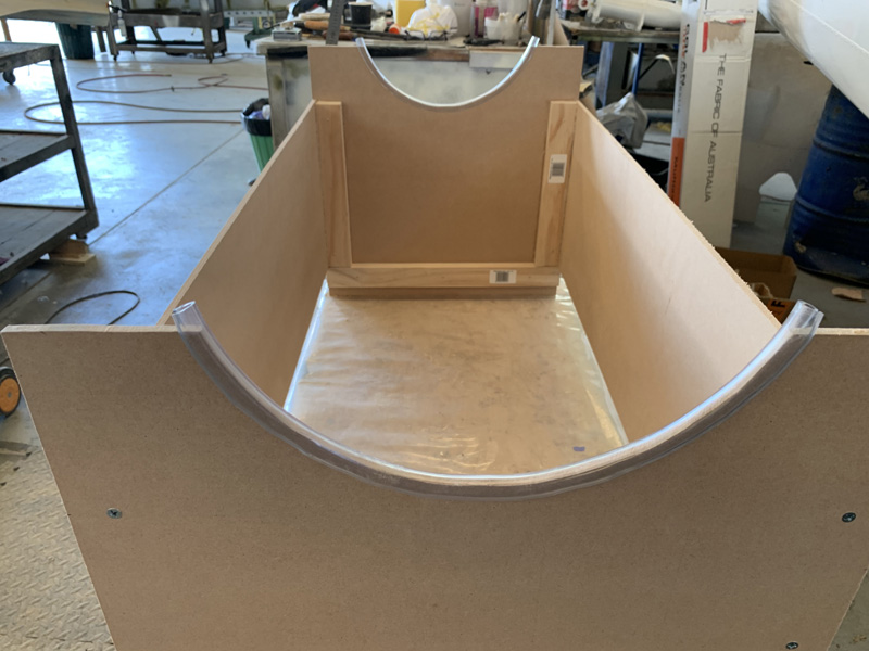
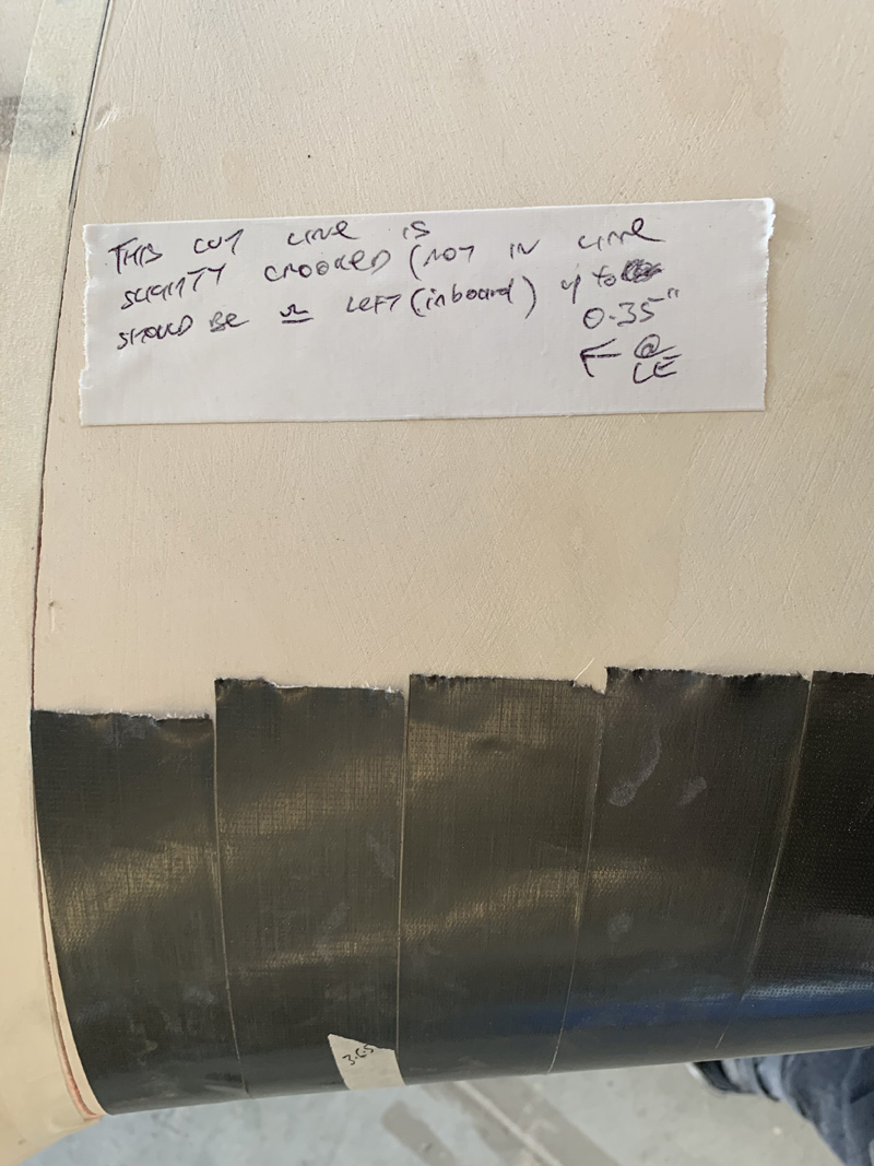
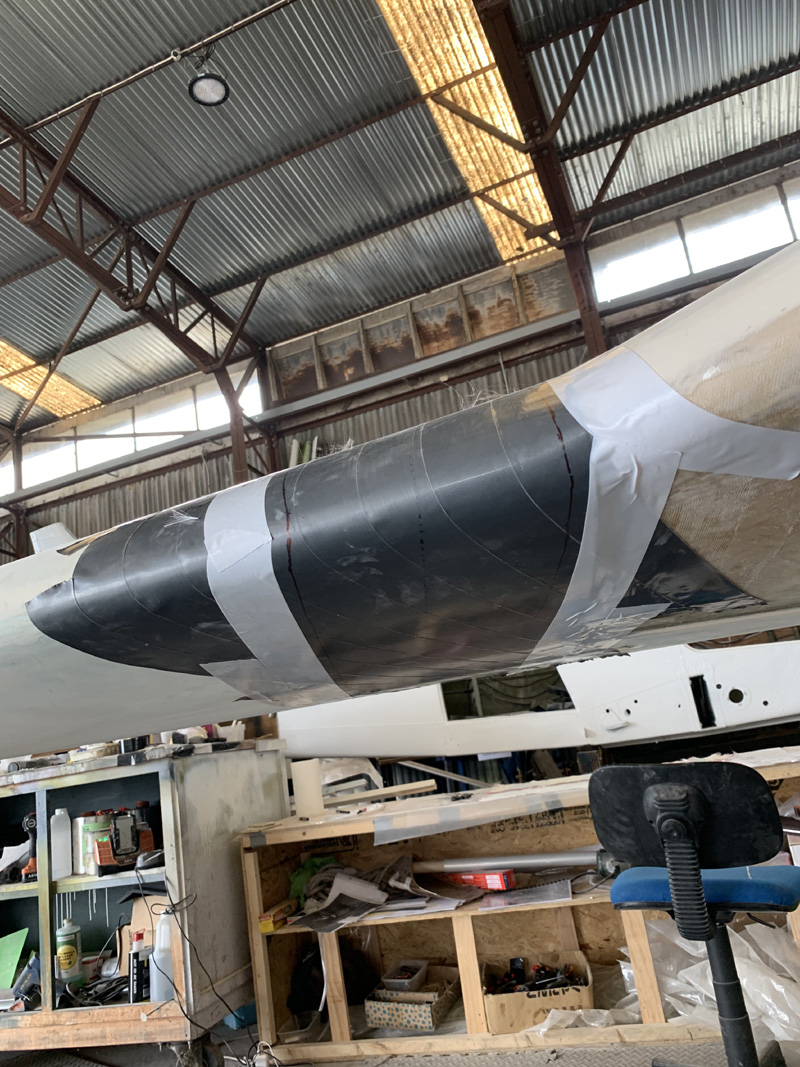
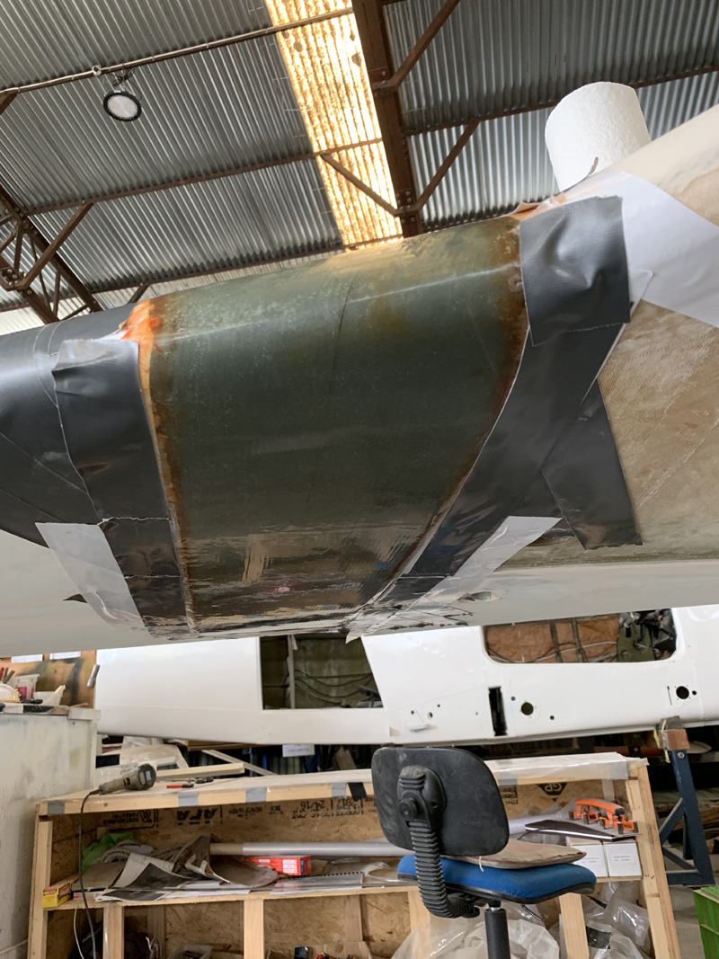
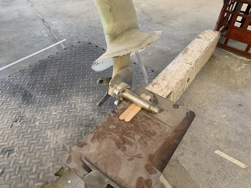
I added the usual micro fill to joins with plastic release on one side.

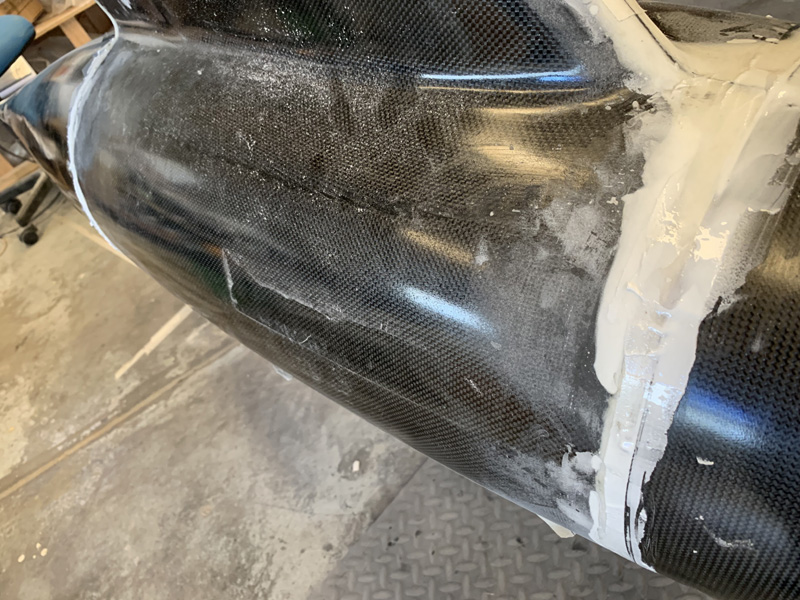
Pretty ugly at this stage.
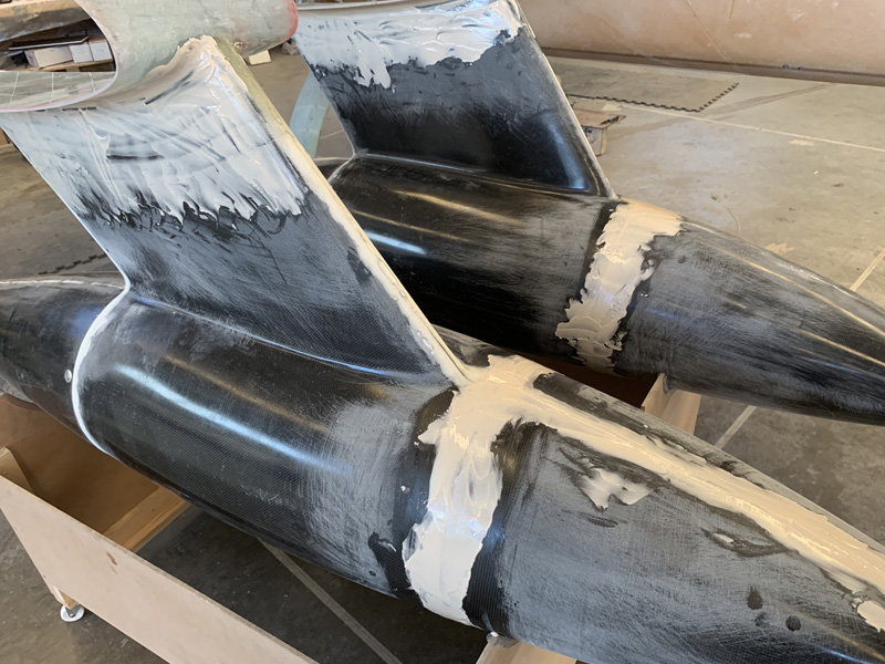
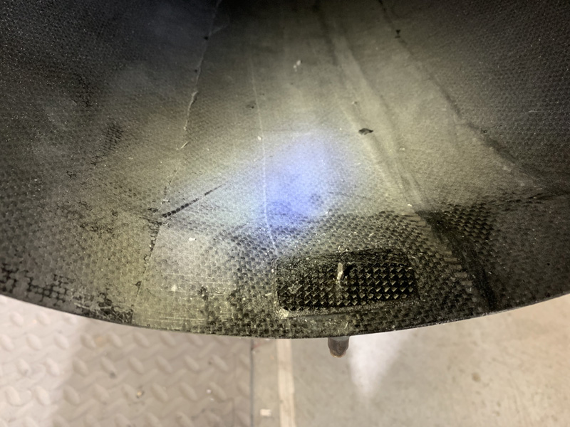
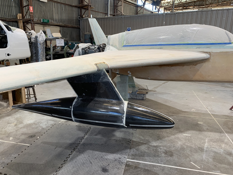
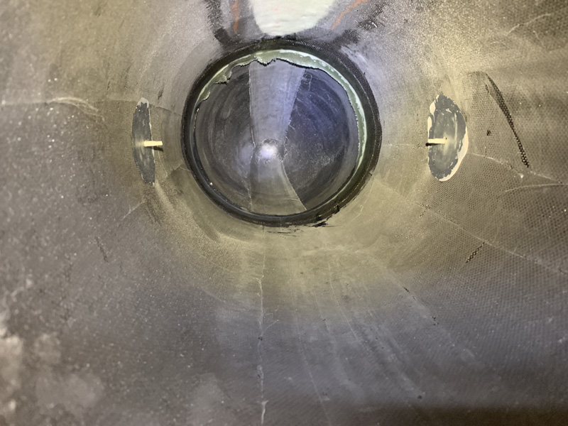
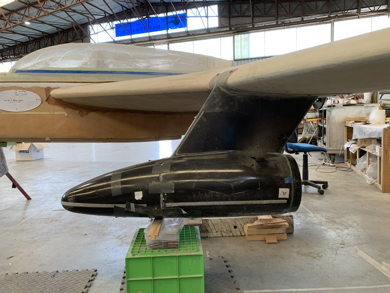
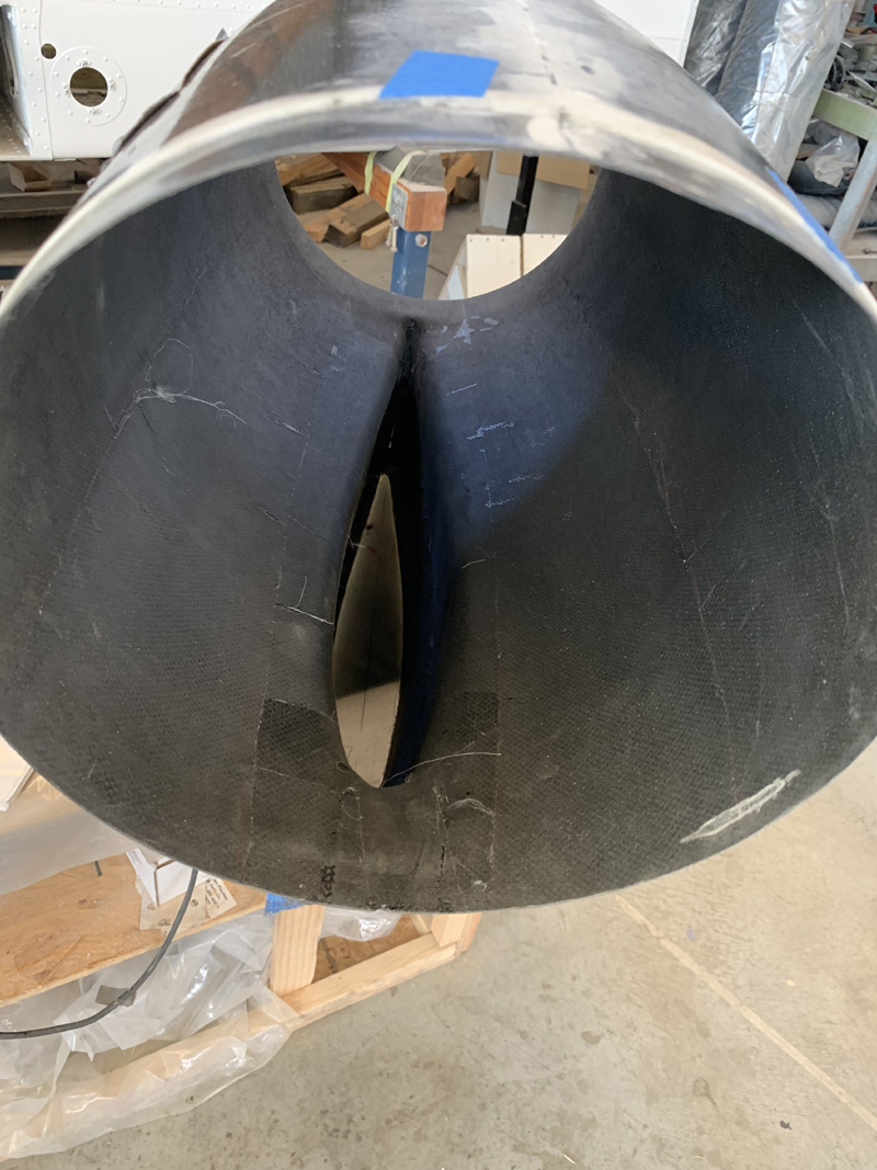
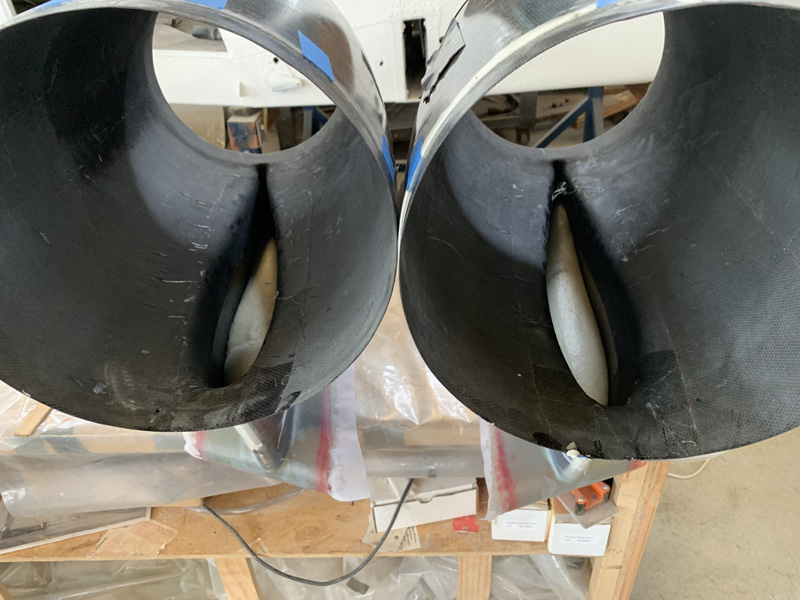
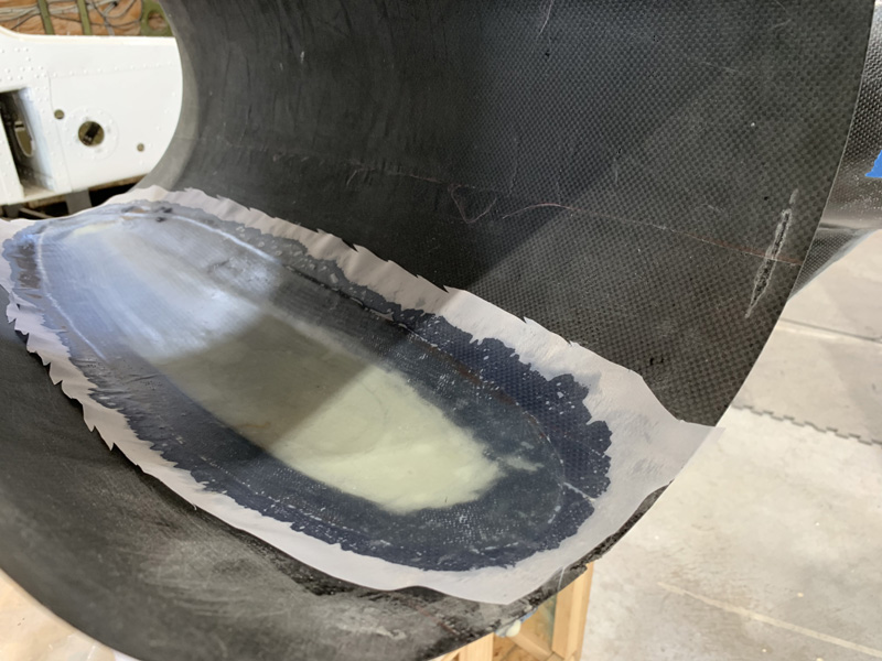
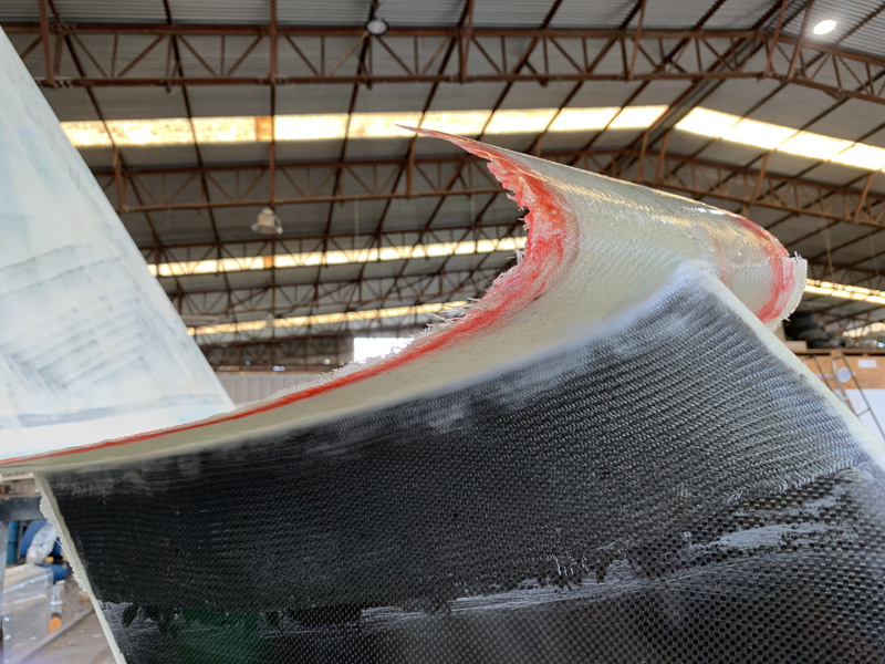
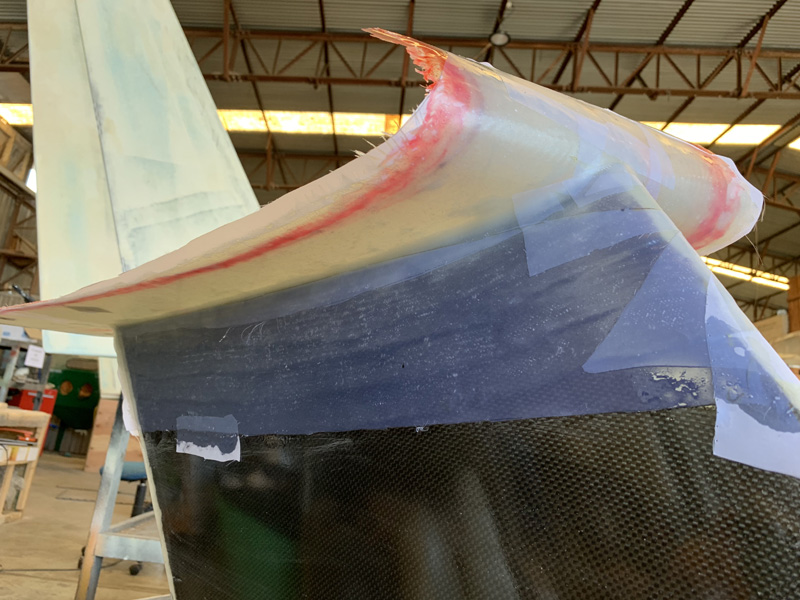
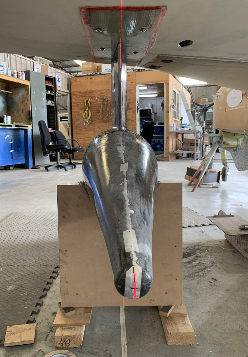
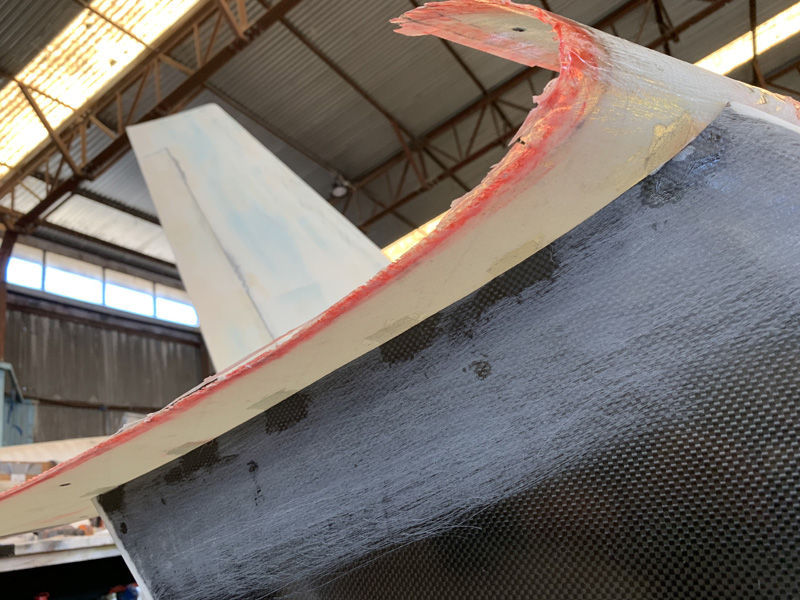
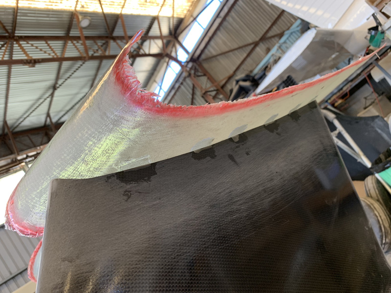
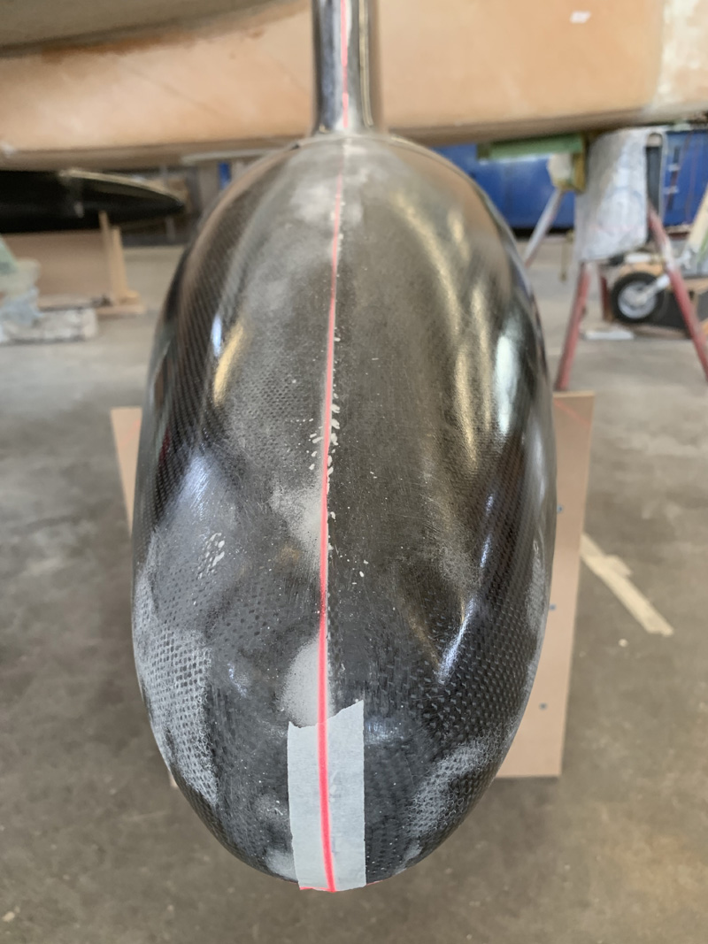
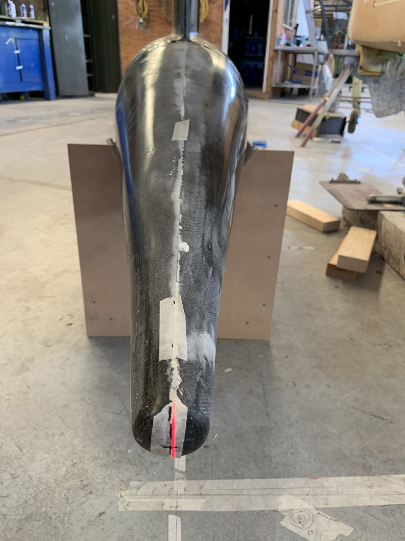
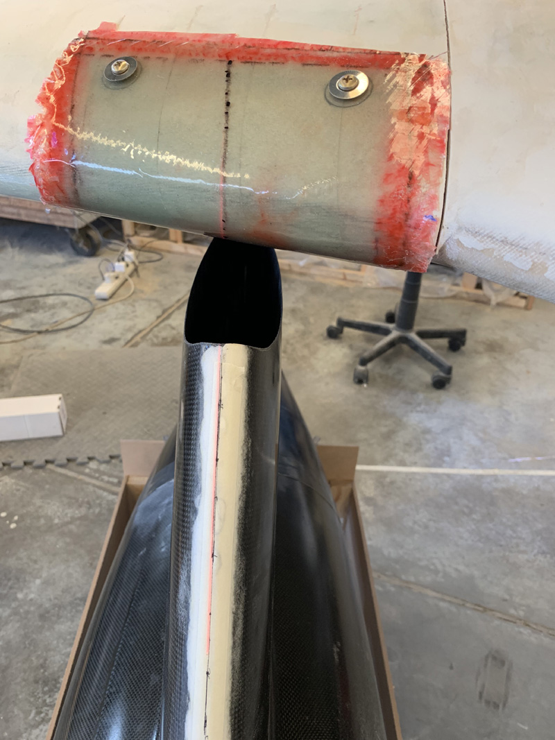
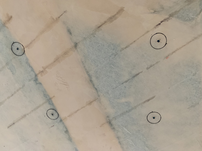
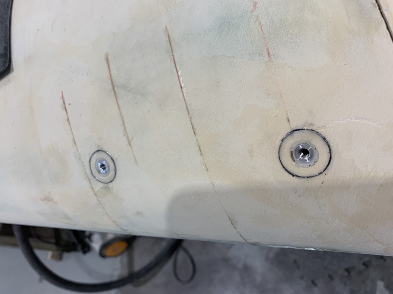
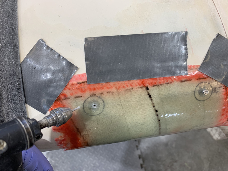
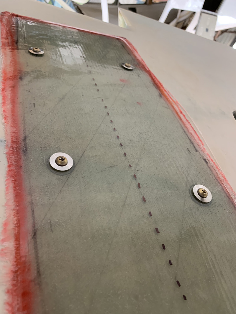
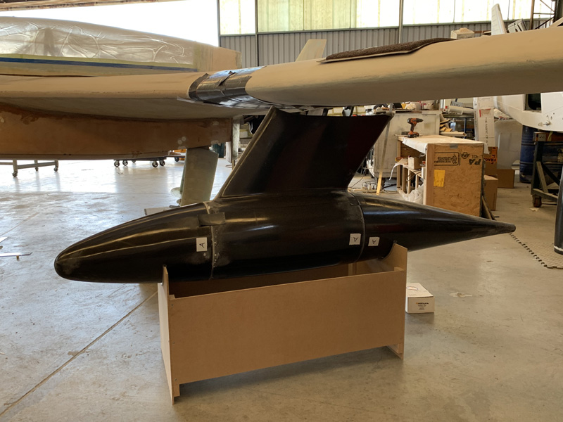
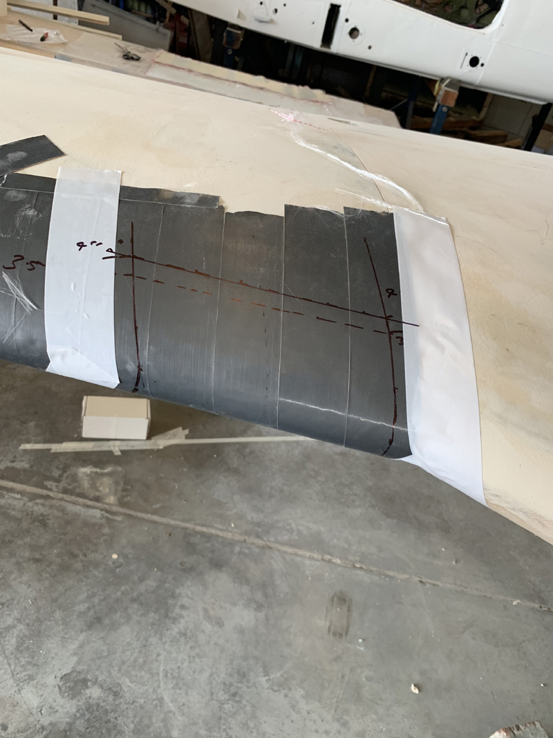
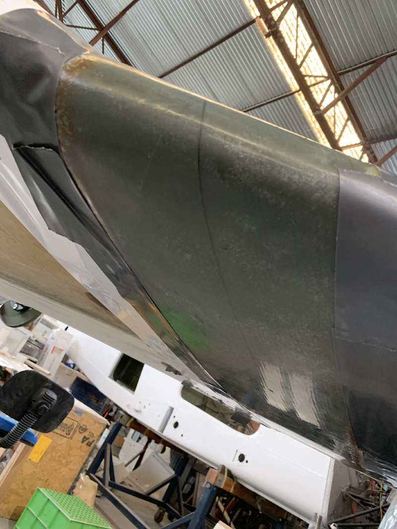
Even more filler.

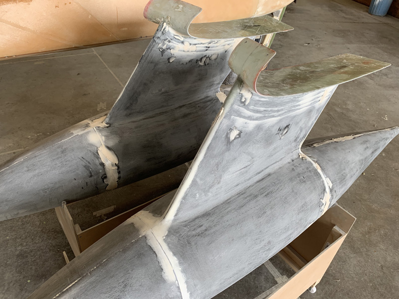
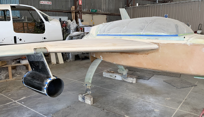
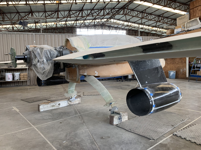
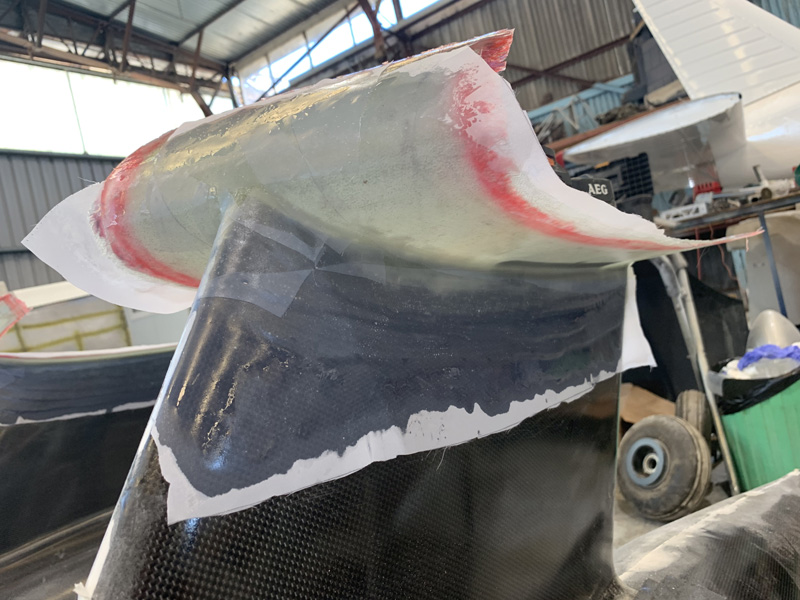
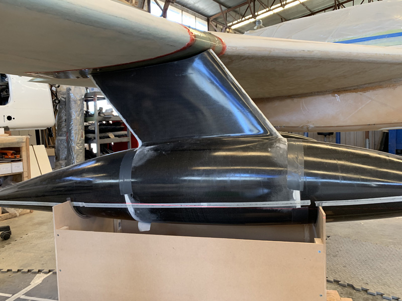
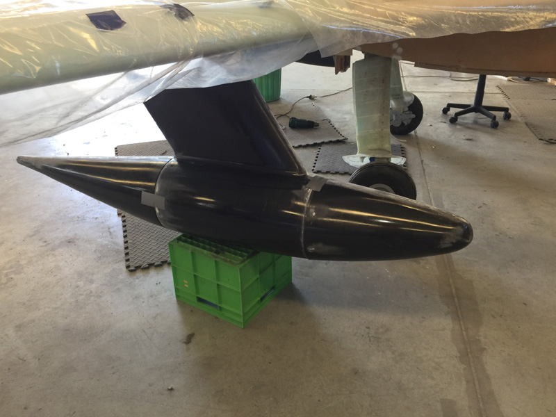
After a lot of sanding this is getting closer. The pods have some wax on them so they need to be sanded before primer. I’ve done a lot more since these photos. Fill and sand, fill and sand. Fortunately there is not a lot of filler that will remain. Its mainly the joins and a bit for the upper pylon layup joins.  Nearly there.

Removable Pod Rear Section

Date:  02-22-2019
Number of Hours:  8
Manual Reference:  no ref

The removable rear section of the pods is secured by three fasteners. I’ve gone for adjustable Camlocs. They are large and robust. The only downside is that the male fasteners have to be completely removable to slide the rear cone off and on. Normally a retaining ring keeps them on the part. I have been very careful with this simple installation because I do not ever want a fastener failure here.

First up I again set up the pods using the laser and my guidelines on the floor. That’s what the wood on the chair is for. The waterline seems the hardest part to keep straight.

The three fasteners go at 6 o’clock, 10 o’clock and 2 o’clock. Using C=D x 22/7. That’s 36″ around making it 3″ between the numbers. Took me back a few years to school days. Not all that much has been useful from then.  Moving on I placed my three clicos and rechecked that the pods were still in line. All good.

I felt that the pods were not really stiff enough for the sort of use they would be getting at the fasteners so I’ve reinforced this area. I was also worried about the rivets coming loose over time so I really wanted more depth. I had some cowl cutoffs in carbon fiber. Perfect!

After the usual prep and prime I’ve secured the 6 reinforcements using the clicos and flox. This will also flatten out the pod curve a little for the Camlocs to sit flush.

I used the supplied template to position for the rivets. Given the curve I had to tweak the holes very slightly later.

I was extremely careful with the countersinking of the rivets. These must be flush for the pod to slide on and off.

The mid section was then drilled out close to the diameter shown. First with my small step drill and then a larger one. Easy.

The three Camlocs were finally installed.

All I had to do on the back piece side was to drill up the holes to half inch. I did this in drill increments so that I wouldn’t loose the center positions. These will be slightly more flush fitting later, but this is pretty close to done.

I rechecked with the laser. They are still in line and the rear section is very firmly held on.

Yes its a gratuitous rear shot. The pods need a fill and fair but otherwise this baggage pod install is getting close.


Pod Nose Cones

Date:  02-20-2019
Number of Hours:  6
Manual Reference:  no ref

Lots of unnecessary pictures in this log edition because these baggage pods without the nose cone and rear look so like a jet engine pod!

A real jet engine profile! That said it is time to permanently bond the nose cones on.

Another unnecessary photo.

After prepping the inside of the pod center and the nose cone I’ve done a 3 ply 2.5″ wide tape half in and half out of the pod. The tape was 35.5″ long. The cone and outer pod lip was then lined with a flox mixture.

I carefully put the pod on and checked the front and side for being in line and secured the outside of the join with gaffa tape.

Here’s a look at the inside. You can see the tape needs a good patting down.

I reached inside here and smoothed down the wet glass and worked the air out. This is at full arms length which with gloved fingers works very well. After I was happy I added peel ply as you see above. That always takes a while.

You might also notice I’ve added a click bond on both sides with a 2 ply circular layup. These will act as tie downs for luggage if I need them. I’ll probably need a stick as well to get things out of the rear of the pods. They are deep!

No longer looking like a jet engine, now its a baggage pod without a tail piece.

On to the right hand side pod.

A quick loo from behind. I warned you there would be unnecessary shots.

Some hours later the right nose pod is on. The method was the same as the left. The peel ply was a pain to put on internally as usual.

Here’s inside the left side with the peel ply removed. The nose is rock solid.

End of the day, both nose cones are on. The removable rear section begins tomorrow.

Inside Pylon Layups

Date:  02-18-2019
Number of Hours:  8
Manual Reference:  no ref

Now to reinforce the pylons.

Somehow I need to get some glass down there sitting on the bottom and lapping onto the sides.

Here’s a closer look. Needless to say you cann’t really get a hand all the way down there.

I wetted out the cloth and used the recommended T shaped tool I made out of a couple of stirring sticks. I did the best I could and would do better the next time. There is some glass down there between the bottom and the sides.

While the glass is wet the idea is that you add some pour foam and this will push everything in place. Too much foam and it will distort the pylon as it expanses. The stuff I have grows about X 8 and gets pretty hot. My plan was to use 100gram batches. Given its 20 second mixing time you need to get on with it!

After about 6 batches I had the stuff grown well over the edges.

Less than an hour later I had a pretty good surface in both pylons which were now glassed at the bottom and full of foam.

The next day I wetted out a couple of plies to seal the foam. It needed a bit of micro first to fill a few voids as is usual.

Glass on, peel ply on. Lets call these pylons filled and sealed and move on.

Outside Pylon to Cuff Layups

Date:  02-16-2019
Number of Hours:  9
Manual Reference:  no ref

Having secured the pod cuffs to the pylons with little glass tabs it is time for the structural connection.

Four plies of glass are to lay between the cuff and the pylon with about a half inch reduction each ply.  There is also a line of flox at the intersection which you can see as a bit of ‘white’ in the corner join. Here’s the first ply on. Usually I’d layup all four plies on plastic at once, but as these are staggered it is not so simple. I’m still doing plastic and foil but one ply at a time. Even worse, I’m doing one ply per side and then overlapping a little at the front.

Here we are all 4 pies and peel ply on top.

The other side looks pretty similar.

Having done one pod in a day it was too much to start the second one. Here we go again, day 2, pod 2. This time I’ve prepared two plies at once. A bit quicker than yesterday. If I had room prepping all four plies together would have been more efficient.

In fact if the glass was not already cut I would have done one big ply and cut it into the eight required strips. I don’t have enough bench space here but thats what I would have done at my home workshop.  Its just that I can’t fit the plane with wings on there!

Here’s the second days pod which looks a lot like the first days.

Two pods both with outside layups at the cuff now. The next job tomorrow is to look at the inside layups.

Oh I put the batteries on the second pod today as weights to keep the cuff on the pylon. The little tabs came off at the leading edge. I REALLY hope its all still lined up correctly. I took a chance and assumed its OK….

Pod Fit to the Wing

Date:  02-14-2019
Number of Hours:  17
Manual Reference:  no ref

Yes another four long days has my pods tentatively affixed to the wing cuffs.

Here are my primary tools. The task is to fit the top of the pylons to the wings or rather the fitted wing cuff. They need to be in line and importantly with correct incidence witch is zero with the longerons already set at 2.2 degrees up.

Fitting just took hours and hours and dozens of refits. Then more hours. I removed a good inch or so of the rear of the pods and nothing at the very tip. The sides did need to be trimmed to fit the wing curvature. Of course I had to remove the same amount for the second pod so they would be a match. Anything else would cause more drag on one side and might tend to yaw the plane.

Finally they were getting close to in line. The required gap at the pylon to wing cuff is to be less than 1/8″ which is quite a large permitted error margin. Given there is a flox fillet and then 4 outside ply and 3 inside, well 1/8″ or more wouldn’t matter at all!

With the ends lined up I just need this incidence to be pretty close.

It is pretty close to a line drawn on the masking tape. That line was previously set of course.

Here we are showing a minimum gap and the cuffs and pods removed from the wing. How did that happen?

Once I was happy with the fit I added six 1″ square pieces of very lightweight glass. You can just see them in this pic. After they cured overnight I was able to remove the 6 screws holding the cuff and get the pods as a unit off the wings

The cuffs are quite securely held to the pylons as long as I am VERY careful. They are ready now for the 4 outer reinforcing plies.

Pod Laser Lineup

Date:  02-10-2019
Number of Hours:  7
Manual Reference:  no ref

Using my self leveling laser today’s task was to continue to get everything in line.

Before mounting the pods I wanted to ensure that the nose and tail sections were in line with the middle part that has the pylon. It is easy to skew these parts slightly to one side in relation to each other. I wanted all of the pod parts to be in line.

I extended my drawing of one of the lines from the fuselage via some tape, the laser and a pen. My idea is that once the front is in line, I can add extra gaffer tape to the nose join and call it good.

With the nose and center part aligned, using the same line on the floor from the other end I checked (and rechecked and rechecked) the nose section. When I was happy that got more tape around the join. It is getting very close in the picture.

With a lined up pod I now needed a zero water line as the third dimension that needs to be correct with the airflow. The middle of the nose and tail are the zero points, I just needed a line between them. That laser sure is handy, and I have spare batteries too.

I ended up with lines drawn on tape and the ends secure. It was so much fun I did it again for the second pod.

With the pods correct next up was to build a floor grid with lines that the laser could sit on. I’m using that parallel point of B.L. 61.5 and then extending those lines fore and aft so I can sit my laser on them.

From the front you can see it will be possible to line it up perfectly.

Then at the rear, again the line up.

All I need now is the waterline to be correct. You can just see in the pic it is more of an intersecting diagonal than ‘in-line’. Its a good .5″ out at the back, meaning I have some carbon pylon to cut. The top should fit within 1/8″ or less all over. I have a LOT of careful trimming to do to get it a perfect fit and correct in three axis’s. I’ll have to go slowly as I want to maintain the same pod pylon length both sides and it is already ‘correct’ at 12″.

Baggage Pod Hard Points

Date:  02-09-2019
Number of Hours:  11
Manual Reference:  no ref

With the cuffs in place the next step is to secure them with six hard points per side. While there are quite a few steps, it is a straightforward process.

I measured and re-measured where these hard points would go. The underneath set is just in front of the wing spar and then another two 4″ back from the pod pylon. I finally took the step to drill the 3/32″ holes and then added clicos to ensure I had it secure. This took half a day, maybe other people would take half an hour. Its not every day I drill into my wings.

Next up was to pop off the cuff layup. It was pretty easy proving again that some shinny tape with no other prep works a treat for release.

I then got all the tapes off, Did a slight trim of the residue and again secured the cuff with clicos. Given the thickness of the release tape I wanted to see if the cuffs were sloppy. Nope, still a tight fit.

Next up I removed the cuffs again and used 3/32″ diameter counter sunk screws to secure the AN960 washer to the wing. The idea is that the countersink area centers the washers. I then drew around the washers with a fine tip Sharpie pen. This process is for later lining up to get the hardpoints very close to perfectly centered.

Here’s the bottom of the wing after I removed the washers and screws. Now we have circles centered around the holes that are in the cuff transferred to the wing.

I’m using 1″ long aluminium hardpoints. To install them its an assembly of a washer with grey duct tape for release trimmed on one side of the washer, a screw as a handle and a lock nut.

I opened up the 3/32″ holes in the wing to 7/16″. I used a drill with a crooked bit of wire about 3/8″ at right angles so I could clear some blue foam just under the skin making a mushroom shaped cavity.

I then made a mixture to fill the cavities for potting the hardpoints. The mix was 25 grams of mixed epoxy, 3 grams of flox and 1 gram on micro. This makes a nice thick paste for the job and worked well even though 4 of the 6 hardpoints per wing are upside down. Of course I primed the hardpoints with pure epoxy and then added some of the mixture. I also primed the holes with epoxy before working in the flox paste mixture. The usual things we do.

The assembly can move a bit in the hole when wet and thats where the drawn circles  allow you to center them very well. I used tape to secure for the cure. As you can see after the cure and removing the tape we have our hardpoints centered in the circles. They are also at right angles to the surface. Perfect. This was all in the pod install instructions and it works.

The bolts came out easily and the washers popped off with a little encouragement. We have hardpoints!

They lined up very closely to the centers of the 3/32″ holes in the 7 ply cuff layup. I just used the dremel to get the centers perfect and then drilled them up to 3/16″

\

Later these will be countersunk and countersunk screws used. For now I’m happy just to add the tinnermans and have the cuff screwed on the wing correctly.

This is under the wing. I’ll trim the cuff after the pylon and pods are fitted. For now I’m happy to move on to fitting the pods themselves to these cuffs.


Baggage Pod Stands

Date:  02-07-2019
Number of Hours:  6
Manual Reference:  no ref

These baggage pods need a stand for setting them in place. The instructions suggest a cardboard box. I’ve gone for something better that can have future use as a ‘holder’ for when the pods are off the plane.

You can see from this that without a stand of some sort these would get damaged in the corner of some dusty old hangar.

I went to the local hardware, “Bunning’s Aerospace” as some of us call it, and got about $30 worth of the cheapest thing I could find to do the job, MDF and pine.

I made a pretty accurate paper template of the pods curve outboard of the center section and to my surprise it fitted both ends well.

Having cut the curve out of the four faces I just made a box with what I had.

A handful of screws later it was quite solid enough.

You might notice that I have some plastic pipe with a cut in one side to made a soft landing for the pods.

It took a few hours and I tried to be neat for a change as I intend to keep this jig.

Under the wing it is a few inches short ready for blocks of wood to get us up to ‘fitting height’. Next up is a trial fit so I can be assured I get the hardpoints in the right places.


Baggage Pod Cuffs

Date:  02-05-2019
Number of Hours:  8
Manual Reference:  no ref

The cuffs are molded to the wing mainly upside down and the baggage pods get bonded to these later. My task is to make accurate marks on the floor and then transfer those to the wing so that my cuff layup is centered and in the correct position.

My little laser self levels with a built in gimbal if its within 5 degrees and tells you if its not. Perfect. Having used large carpenter squares off my center line I could easily measure out what became 61.5″ (BL61.5). This is about four inches from the wing to strake join on one side. Which means with allowing a maximum 7″ cuff width I’ll have a half inch buffer.

I measure out the 61.5″ from the centerline down at the engine end again using the square from the centerline to get a 90 degree line. I marked the line on tape and as you see above labeled the 61.5″. A thing with the laser is that after a few feet it’s hard to see the line on the floor anymore. In the above pic you can see that I have a box with a perpendicular line. Amazing, no line visible on the floor but there it is on the box. Woohoo. You can now easily see the laser mark and line up the two points to get a line parallel to the centerline under the plane but 61.5″ out.

Here’s a wide view and I hope this explains what I’m doing a little better than the words. Yes the tape is a little crooked but the line on the tape is dead straight. I’m just using cheap masking tape on the floor to draw on rather than something more permanent.

In this pic you can see the two big squares I’m using. I put them back to back exactly on the centerline then it’s easy to just draw the 90 degree line. Make sense? If not, drop me a note. Frankly I have trouble understanding this stuff but when I tell people they get it right away. Either I am fantastic at explaining it or pretty dumb in having trouble with something that is obvious to others. No need to tell me which.

OK I finally found my missing .3 to .4 of an inch discrepancy that seems to be all over this when I got the serious measuring happening. All it is, is a slightly crooked line in that stake to wing join. I am really within about .10 to .15 of an inch from perfect in reality …and that amount would be ‘in the noise’ as we say.

This means that my decision is to have the baggage pods exactly the same distance from the centerline despite it being slightly closer to the crooked line on one side. That slight crookedness is not really apparent until you measure. Its looks pretty straight really until I point it out and even then…. Well trust me, the plane is nearly perfect hahaha. My lines here and there, not so much.

The really magic thing about the laser is that while I had it lined up on the floor and, as I showed, it magically climbed up my box at the same time. Well it also shined perfectly on the compound curve of my wing edge, right at BL61.5 Pity it doesn’t show in the photo eh?

In the above pic you can see a dotted line in the middle. I just put marks where the laser was on the top and bottom of the wing. Then I marked out a line 3.5″ each side. Of course I also used the laser to help me position that cloth tape on the wing so I could draw on it later. The tape should be around the thickness of primer and topcoat paint as well as a release medium for the cuff.

The white tape on the sides is a gross outline so that when the wet and sticky cuff is going on I will have something very easy to see as outside guidelines. If I get the glass within those white tapes it should work out.

The pods came with pre-cut glass as you see above. No way am I going to get 7″ width out of these. They are really cut tightly. Long-EZ pods, the smaller ones have a 6″ width cuff. Mine might be 6.5″ or so. We shall see.

This is the left side cuff glass with all seven plies wetted out. Its about 32″ in length and I sure hope its enough. You can see the 7″ width lines top and bottm so I am really right on them.

I’ve wetted it out on plastic with a centerline and the 3.5″ guidelines. The sharpie pen marks are on the underside so the ink doesn’t bleed into the wet glass.  You might note that I have trimmed the plastic to just above and below the glass and only a little excess at the top and bottom. I have differed from the instructions here.

I prepped the tape on the wing with pure epoxy using a folded paper towel as an applicator. This and the seven plies took two lots of 120 grams of mixed epoxy with not much over.

Again unlike the ‘instructions’ I only needed one assistant and no practice was required. I had the other person hold the longer, under wing section, at the end with two hands. I lined up the front section of the layup just over the 3.5″ mark and under the 4″ mark I’d made on the top of the wing. (You can see these marks several pics back) When I was ready I set it down and ensured my assistant had the rest of the layup in line with my center marks on the wing and plastic and about two inches below it. I then pushed the layup onto the wing front to back.

It immediately stayed put with no problems at all despite being mainly upside down. I eased any air out the sides and ends. Then I used a squeegee to really get it laid down nicely.  When I was 100% happy I added tape to the ends and to the plastic sides. That layup was not going anywhere. Both sides are now done. Well at least the cuffs are on the wings.

On to the next step tomorrow.

Baggage Pods 1

Date:  02-03-2019
Number of Hours:  12
Manual Reference:  

The baggage Pods arrived November 8 last year. They are one of the very few pre-made items on this build.

These came from Dale Martin in the USA, are carbon fiber and very well made. Thanks Dale. At time of writing they are still not on his website. I guess he is busy making more parts. I was pretty keen to get them out of the wooden packaging box and stick them in place to see how they look. Yes they cost a bomb too!

I don’t think I have it quite the right way around here but you get the idea. Installing them is going to be a huge job. They need to be in perfect alignment or I will have unnecessary drag.

I spent two full days trying to get the fuselage aligned and checking various points. The longerons are at 0.00 degrees. The nose is 2.2 degrees up which I think will be my fast cruise position. Obviously the nose is weighted down so it won’t go backwards. The wings measured within about 0.2″ just hanging in space to the ground which was surprisingly good. I have stabilised them with the pod box and a workbench and some books so it is nice and stable. The wings are under slight tension to keep things steady.

I removed the wheels and just have the axles on wooden blocks. Those tongue depressors and clip board helped me achieve the 0.00 across the longerons.

Here’s a view of my pod box acting as a wing holder and some old computer books making the height just right as well as a bonus soft surface.

While I’d spent a couple of days crawling around trying to make the lines on the fuselage work, I kept finding about .3″ overall discrepancies using plumb bobs and rulers. My nose lines and the canopy lines and the line at the firewall are not perfect. However, while crawling underneath I found I had a continuous line under the fuselage still visible. Perfect!

More crawling and I discovered that my laser (pictured below) can make a line on the floor and on the fuselage bottom at the same time. As another bonus it shines an extra laser dot straight up which I could center on the line. (pic above)

Armed with all this I was able to lay some tape and get a line on the floor exactly below the line on the fuselage. To my surprise this lined up with a plumb bob on the nose which turns out to be exactly in line, not off to one side a little as I thought.

Above you can see my line on the floor. At the back you might notice what are two large carpenter’s squares. I’m using these to help get parallel lines on the floor at particular measurements. I think this will work out OK. I’ve also spent quite a while on the install directions and other builder websites. As usual James Redmond’s was very handy. Thanks James!

I need a few more measurements and then some prep work and I can begin the first 7 ply layup which are the wing cuffs.


CategoryLogsHours
All157617079
Uncategorized135
Ch 3 Education220
Ch 4 Fuselage Bulkheads25231
Ch 5 Fuselage Sides32283
Ch 6 Fuselage Assembly30270
Ch 7 Fuselage Exterior14140
Ch 8 Roll Over/Seat Belts990
Ch 9 Main Gear/Landing Brake71642
Ch 10 Canard28287
Ch 11 Elevators36298
Ch 12 Canard Installation12102
Ch 13 Nose and Nose Gear1291097
Ch 14 CenterSection Spar57525
Ch 15 Firewall and Accessories448
Ch 16 Control System27237
Ch 17 Roll/Pitch Trim System654
Ch 18 Canopy70502
Ch 19 Wings, Alierons1271090
Ch 20 Winglets/Rudders71528
Ch 21 Strakes - Fuel/Baggage65437
Ch 22 Electrical System591031
Ch 23 Engine Installation961152
Ch 24 Covers/Fairings/Consoles25202
Ch 25 Finishing561084
Ch 26 Upholstry340
Fuel System46310
Rollover1050
Cabin heating System60331
The Ferry Tank335
Blog2694182
Build Mods2252513
Nose Gear Doors856
Wheel Pants/Gear Leg Fairing40473
Oxygen System762
Roll and Pitch Trim964
Winglet Intersection Fairings445
Baggage Pods11104
Pilot Side Windows437
RAM Air & Hellhole Cover15177
Main Gear Beef Up322
Post Cure124
Fire Extinguisher16
Wing Fences13
EVS (Enhanced Visual System)130
Hinge Upgrade115
Cowl Keeper110
Rudder Gust Locks19
Cooling20607
Taxi Tests42
Flying10

Complete the Test Flight Program

2025/6/30 10:26:01

Round Australia in Four Flights

2026/4/1 10:26:01

Round the World Departure

2026/8/22 10:26:01

Rough River Flyin, Sept 23, 2026

2026/9/23 10:26:01

© Copyright 2025 Dave Berenholtz