• Home
  • Flying
    • First Flight
  • Build by Chapter
    • Ch 3 Education
    • Ch 4 Fuselage Bulkheads
    • Ch 5 Fuselage Sides
    • Ch 6 Fuselage Assembly
    • Ch 7 Fuselage Exterior
    • Ch 8 Roll Over/Seat Belts
    • Ch 9 Main Gear/Landing Brake
    • Ch 10 Canard
    • Ch 11 Elevators
    • Ch 12 Canard Installation
    • Ch 13 Nose and Nose Gear
    • Ch 14 CenterSection Spar
    • Ch 15 Firewall and Accessories
    • Ch 16 Control System
    • Ch 17 Roll/Pitch Trim System
    • Ch 18 Canopy
    • Ch 19 Wings, Alierons
    • Ch 20 Winglets/Rudders
    • Ch 21 Strakes – Fuel/Baggage
    • Ch 22 Electrical System
    • Ch 23 Engine Installation
    • Ch 24 Covers/Consoles
    • Ch 25 Finishing
    • Ch 26 Upholstry
  • Build Mods
    • Liquid Cooling, Numbers, Weights and Flow
    • Cooling
      • Solving Ground Cooling 1
      • Solving Ground Cooling 2
      • Solving Ground Cooling 3
      • Solving Ground Cooling 4
      • Solving Ground Cooling 5
      • Solving Ground Cooling 6
      • Solving Ground Cooling7 – Test Data
      • Solving Ground Cooling 8 – Flap Building
      • Solving Ground Cooling 9 – Hinges
      • Solving Ground Cooling 10 – Lower Flaps
      • Solving Ground Cooling 11 – Upper Flaps
      • Solving Ground Cooling 12 – Completed
      • Solving Ground Cooling 13 – Update
      • Cooling the Beast 1
      • Cooling the Beast 2 – Lower Cowl Expansion
      • Cooling the Beast 3 – KW Oil Cooler Diffuser
    • EVS (Enhanced Vision System)
    • Cowl Keeper
    • Rudder Gust Locks
    • Wing Fences
    • Post Cure
    • Hinge Upgrade
    • RAM Air & Hellhole Cover
    • Main Gear Beef Up
    • Pilot Side Windows
    • Baggage Pods
    • Winglet Intersection Fairings
    • Titanium Rollover
    • Nose Gear Doors
    • Wheel Pants/Gear Leg Fairing
    • Cabin heating System
    • Fuel System
    • Roll and Pitch Trim
    • Oxygen System
    • The Ferry Tank
    • Cruise Angle Indicator
    • Fire Extinguisher Install
  • Round the World
    • RTW Route East #12 rev2
    • Survival Equipment
    • Training Flights
  • Other Stuff
    • Blog
    • Could You Reincarnate as an AI?
    • XEZ Long-EZ Interview Jan 2026
    • Around the World: RAAUS Sport Pilot Issue 110
    • Summary Feb ’24 from an SAAA Meeting
    • AOPA Pilot 27th Sept 2019
    • Taxi Tests
    • Build Tests
    • Flying Stories
      • A Long Easy Dream ’06
      • Townsville ’07
      • Cairns ’08
      • Albany ’08
      • East Coast ’08
      • Brisbane ’09
      • Cairns ’10
      • Perth ’10
    • Non Build Mods
      • F16 Scoop for JZE
      • Ram Air Box for JZE
      • Strange Tips
    • Milestones
    • Links
  • Contact

Blog

Home
Blog

Reinstalling the Engine

Date:  01-26-2026
Number of Hours:  0
Manual Reference:  no ref

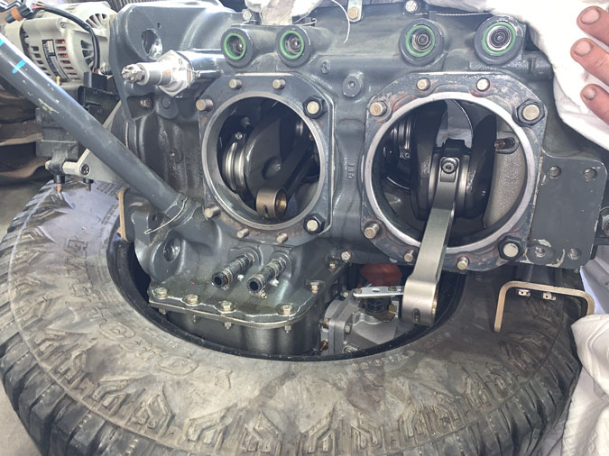
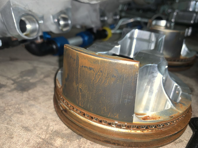
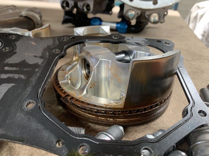
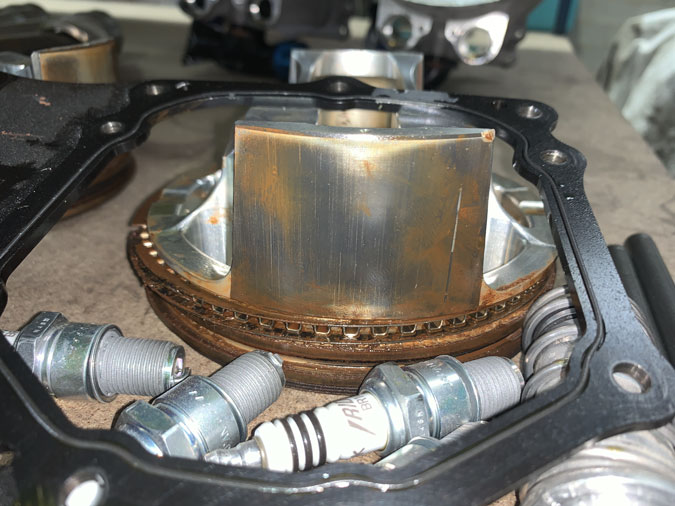
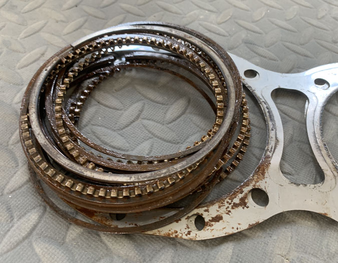
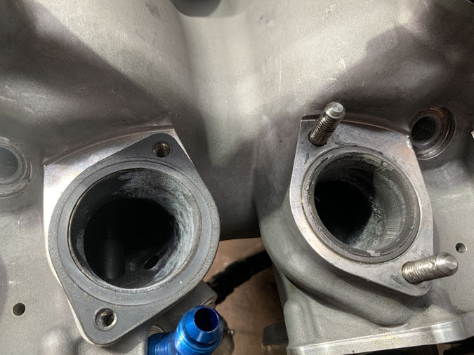
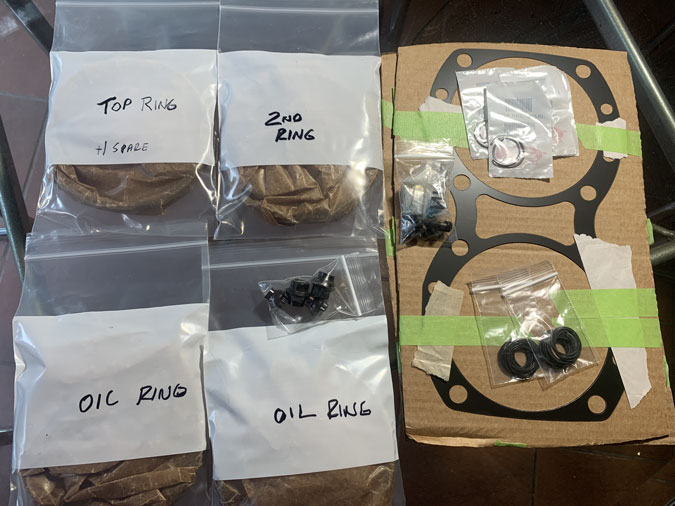
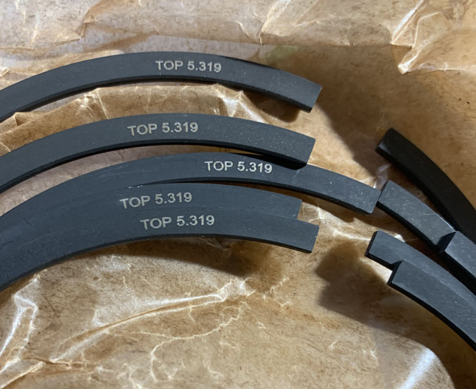
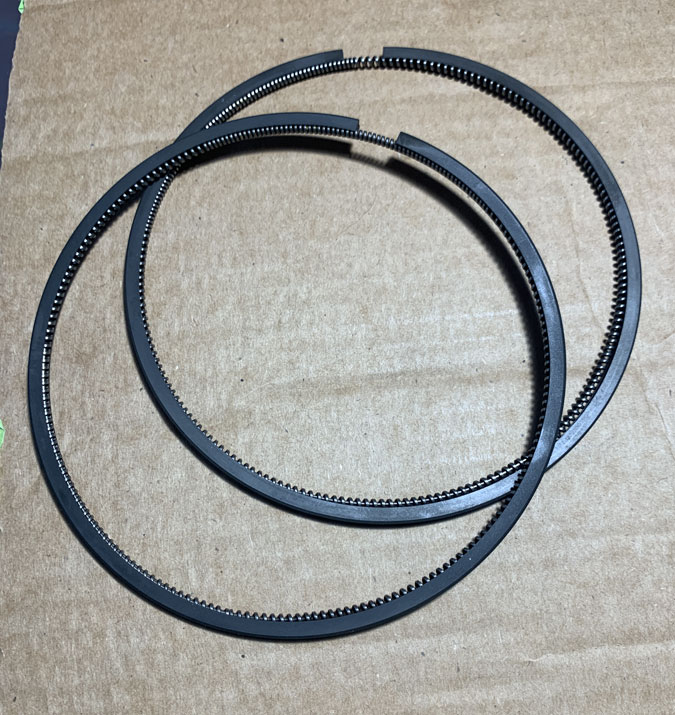
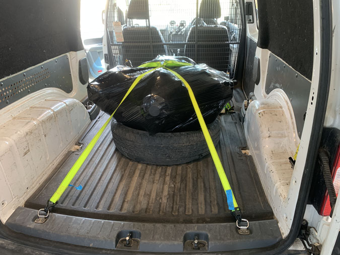
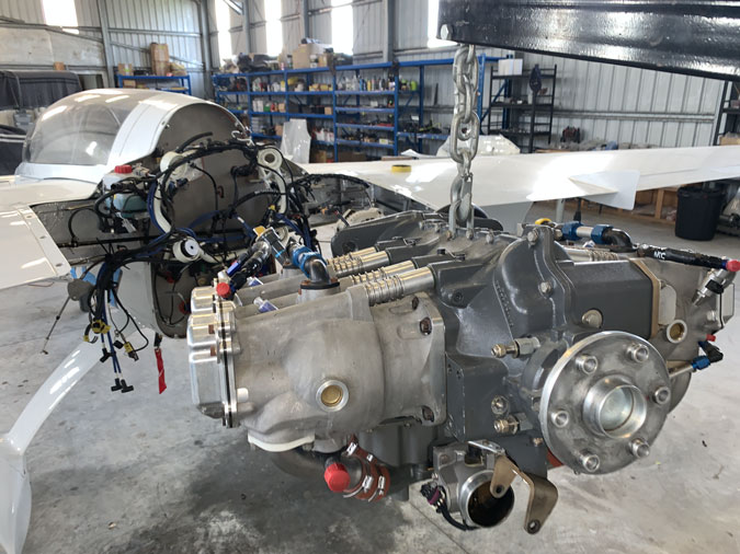
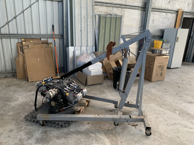
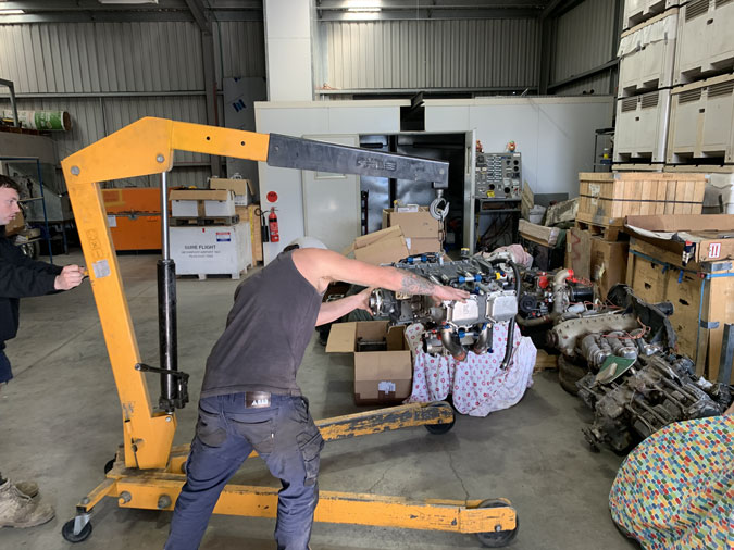
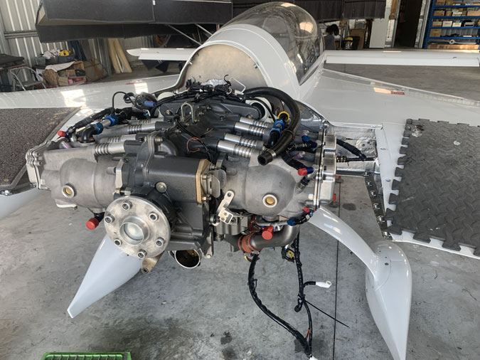
December 6th. 2025 and the engine is back. In the end it was just a set of rings.

I pretty much got it back on the mounts on my own but I did get a bit of help to seat the final rubber. That was a couple of days in the end. Now I should have hooked up the small alternator and a couple of pipes while the engine was a few inches off the mounts. I thought I could struggle with the lack of clearance later… That decision soon came back to bite me.

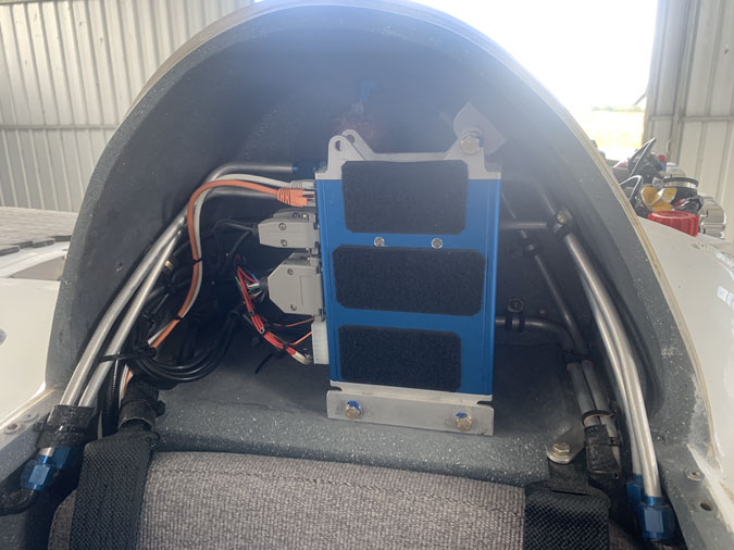
Yes, heres’ the first gottcha, all that stuff had to come out now.

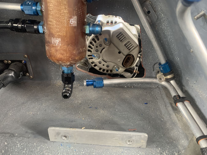
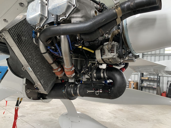
The plug at the back of the alternator needed another 1/4″ or so to fit in and I couldn’t do it with the engine installed. Yeah, should have done it when it went in. So a bit of work to get there, then 2 seconds for the plug, then it all back in again. Chalk up another day gone.

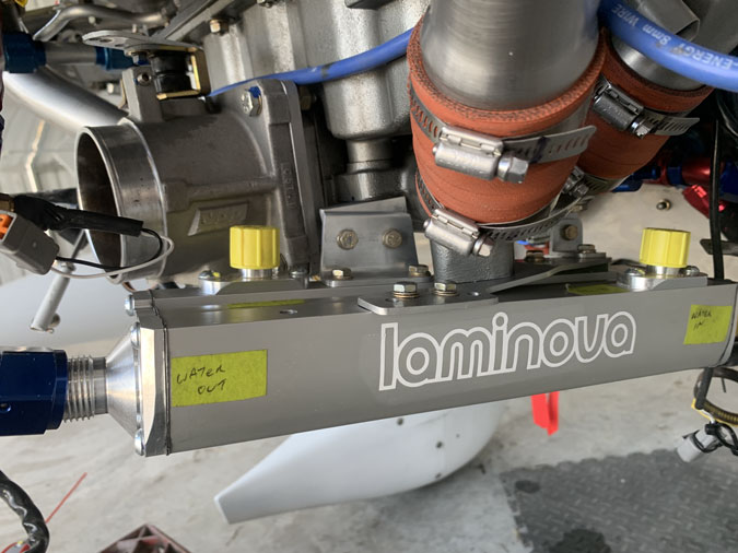
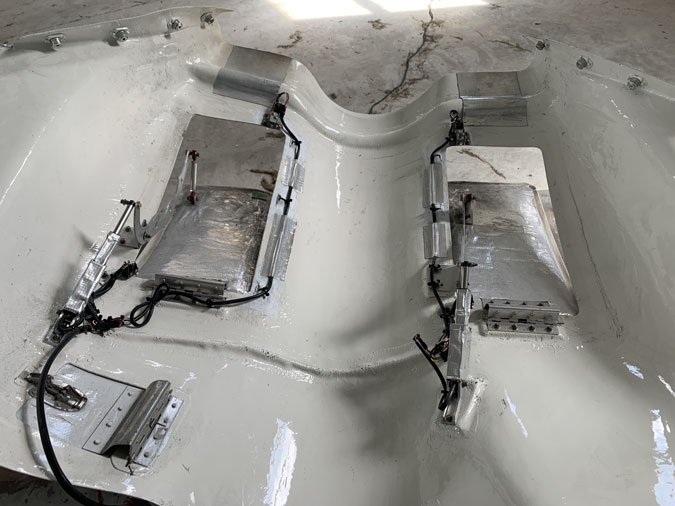
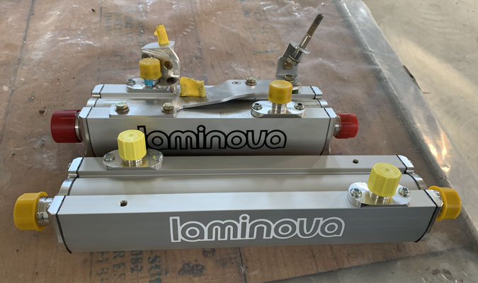
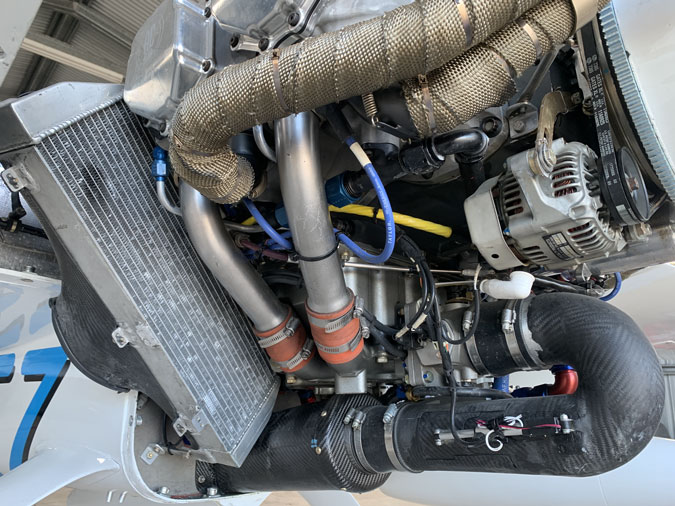
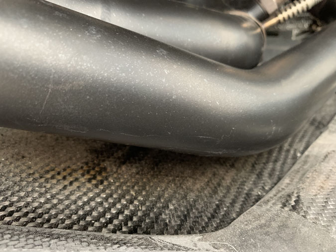
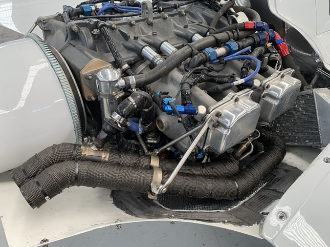
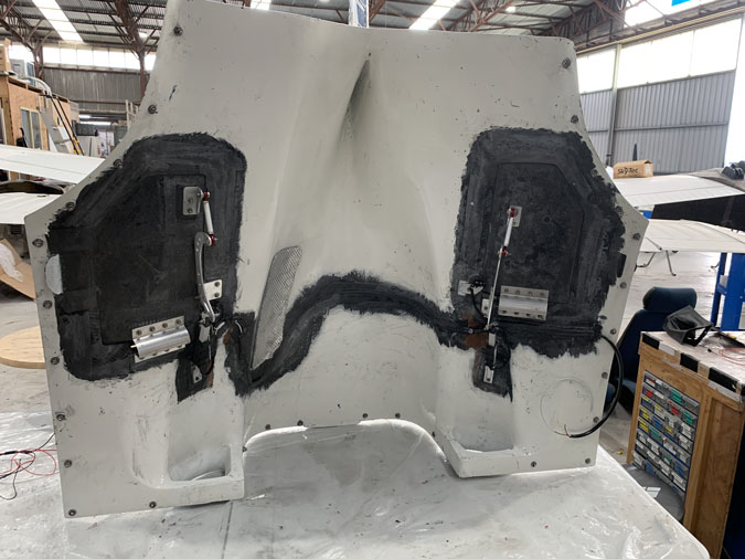
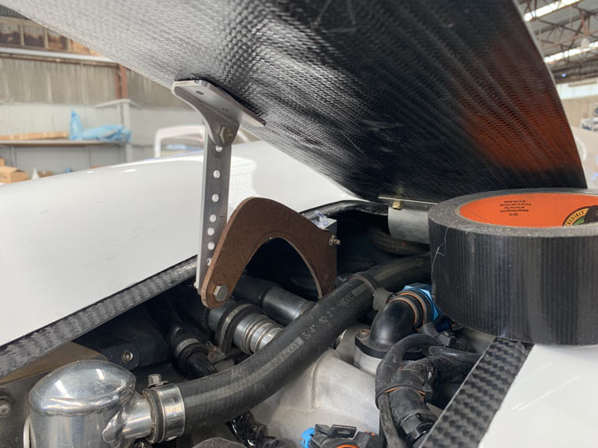
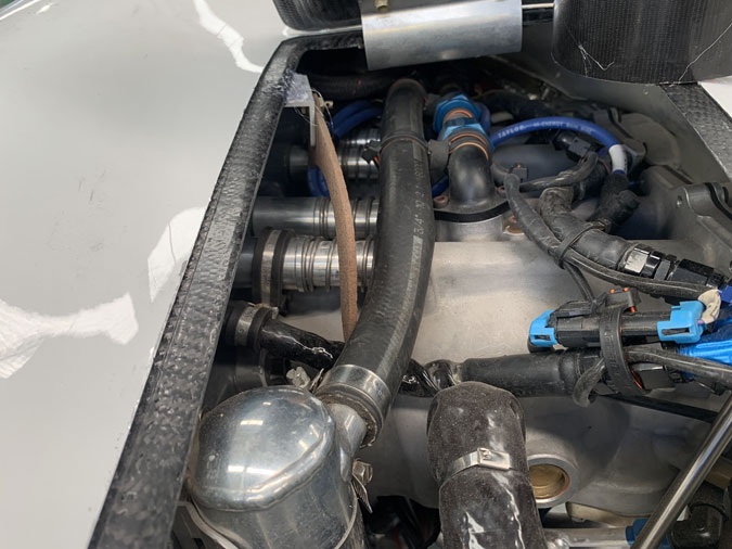
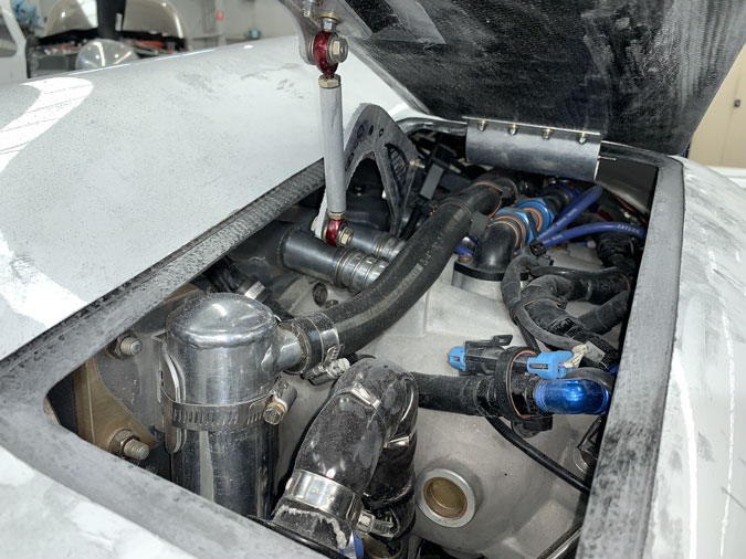
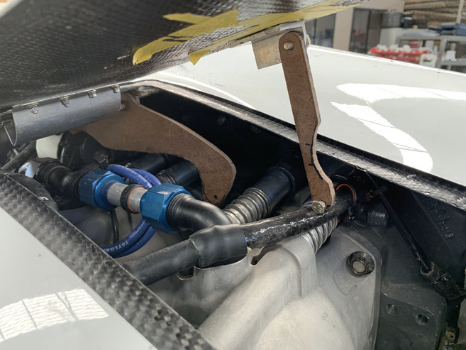
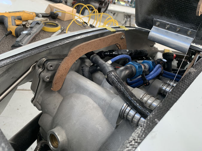
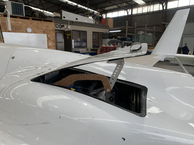
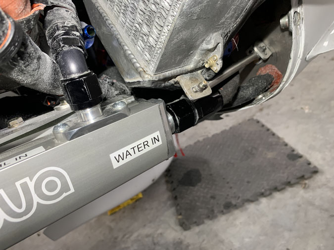
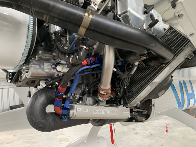
I’ve bought a larger heat exchanger. This ones a bit longer than the last. Laminova ECD54-329 the previous was the 250mm version. I hope this will improve the cooling balance between the coolant/cylinders and the oil. If not I am going to need a bypass system which would be more pipes and complexity. I had quite some challenges fitting this longer unit.

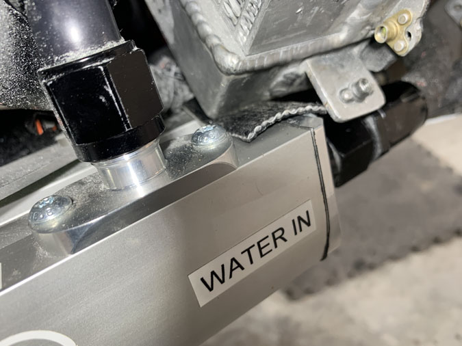
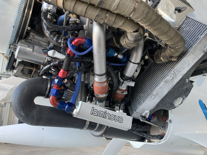
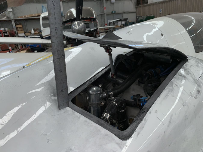
It really doesn’t fit. I tried denial for a while. That radiator is just too close.

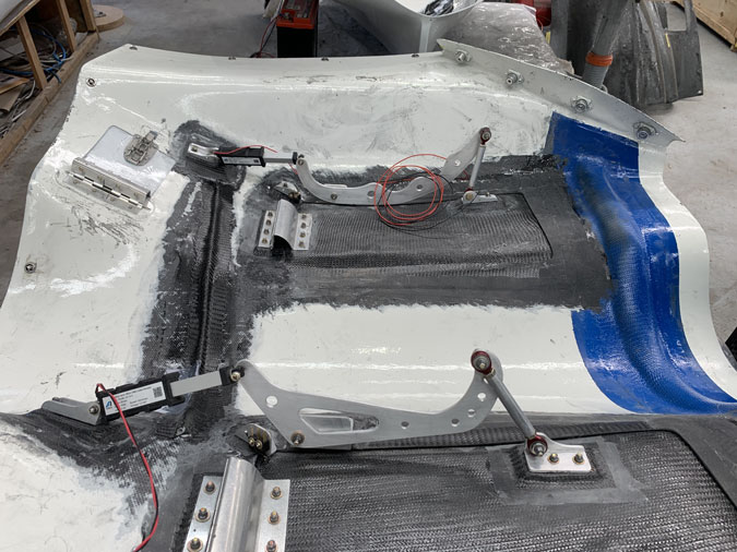
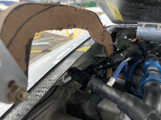
So by mid January I pulled the radiator, had the corner chopped off by my excellent welder friend and now there is good clearance. Of course I had a lot to go through before that happened.

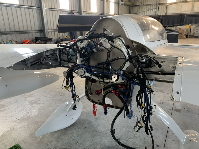
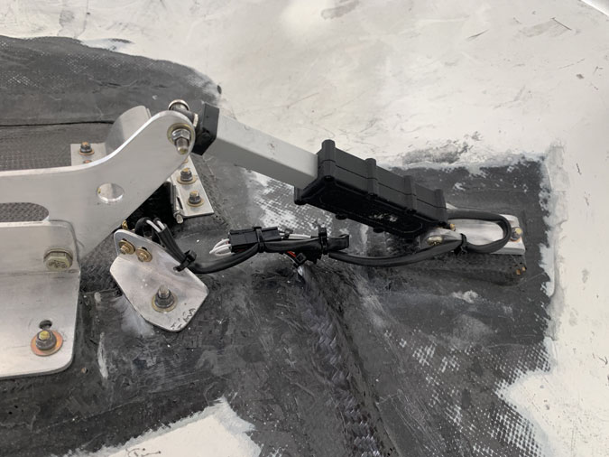
This is after two weeks work fitting electrics and pipes, I realised I needed to pull the engine out again. Just one little -4 size pipe for the oil pressure simply could not be fitted. You couldn’t even see it and braille skills required! I had no idea that was going to be so difficult and I was reluctant to pull the engine again given how tough it is to get the mounts sitting just right.

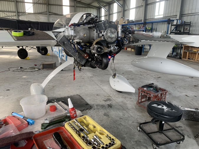
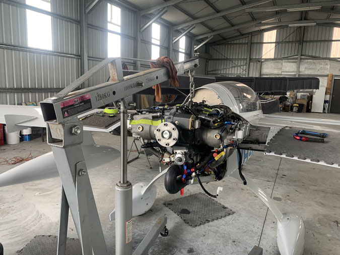
Now we are at 30 December 2025. I got my little oil pipe on with the engine removed back a few inches. In the end I had two very skilled LAME’s help me get it back on the mounts. This is not a one person job. During the process I was asked, “Get me a bigger hammer” Now coming from fixing guitars as a background I don’t tend to think that way on airplanes. You need to know what you are doing. I will say the engine now sits on its rubber Lord Mounts better than it ever has.

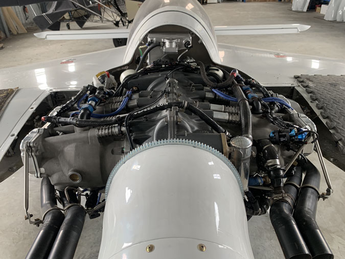
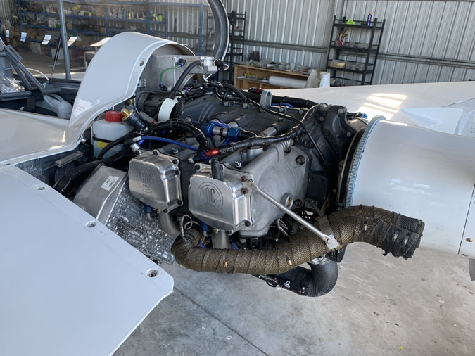
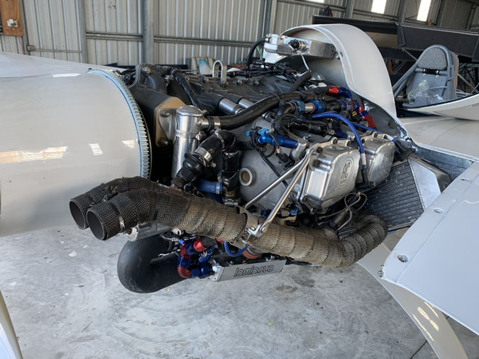
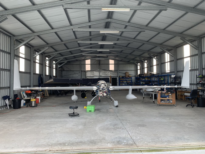
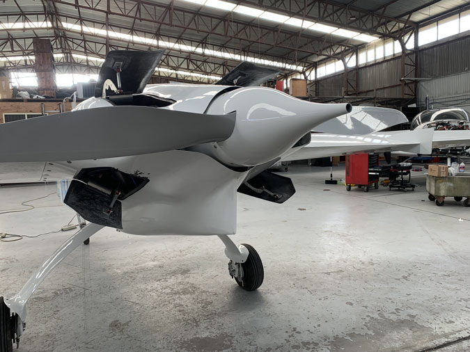
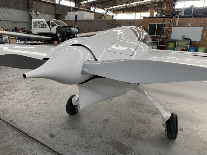
Finally, ready for some leak testing before the first ground run.

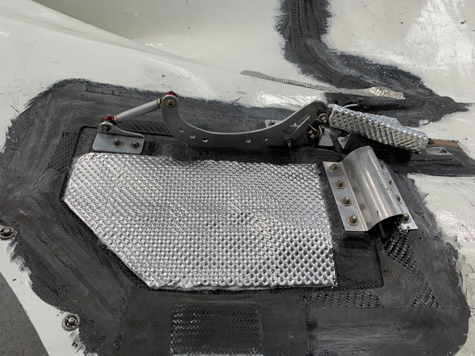
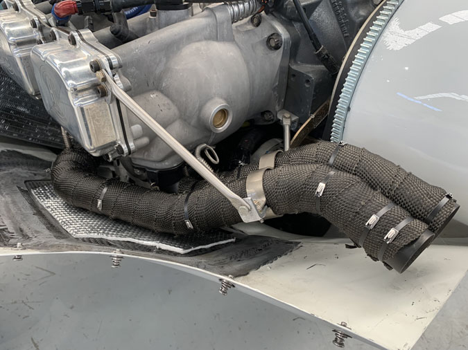
I’ve decided to leave off the exhaust wraps for now. I think I need more heat in the cowls after flying to help it cool down at a closer rate to the coolant. Particularly while I am using straight mineral oil.

It has been a huge job to this point.

Before the first start attempt I did run the fuel pumps. I can get full pressure without the engine running which is great. I had a few leaks and addressed them. A couple of things not done up enough.

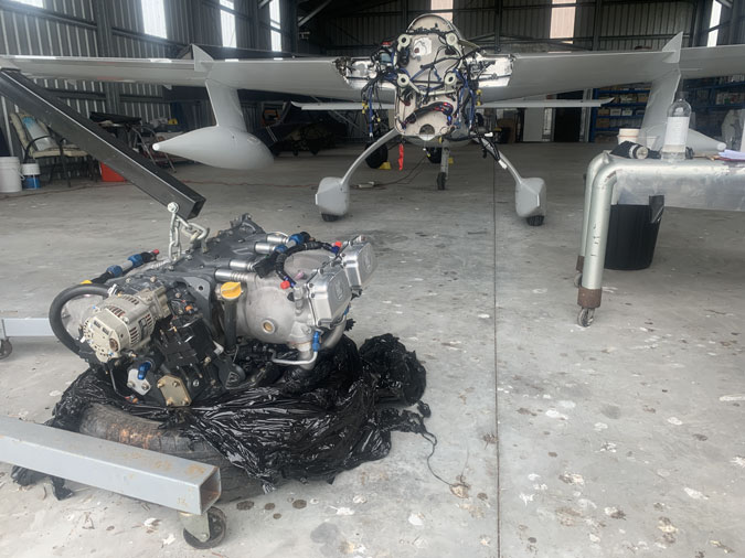
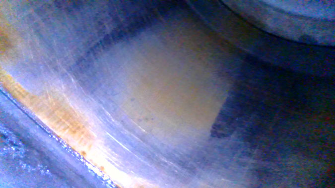
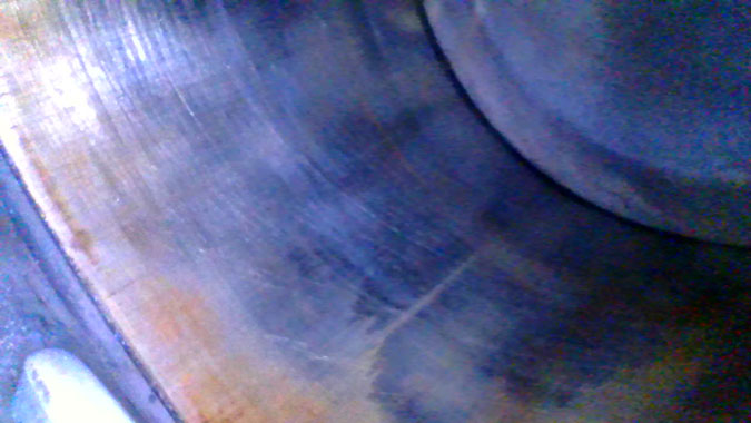
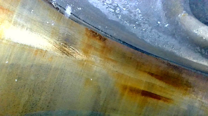
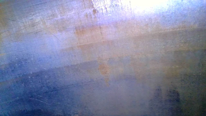
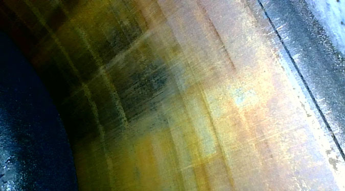
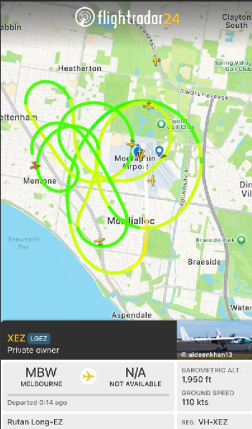
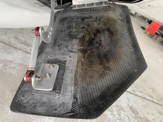
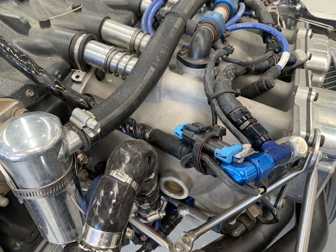
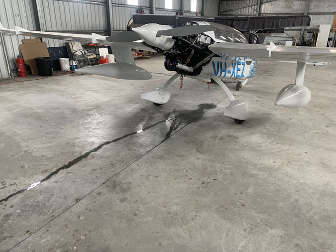
24 Jan 2026 I ran the engine. It started on the third try. I was pretty happy with that. It meant I hadn’t stuffed up all the electronics and ignition leads for a start. A few things on the first brief run had to be tightened up. I then got a start on the first crank and ran for a few minutes at 1000rpm and then up to 1500rpm. Well that extra pressure showed up a significant coolant leak. Otherwise I seem good.

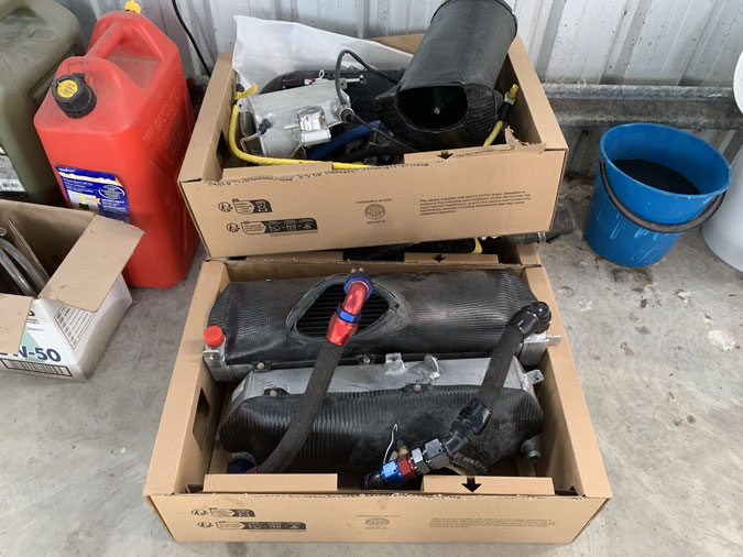
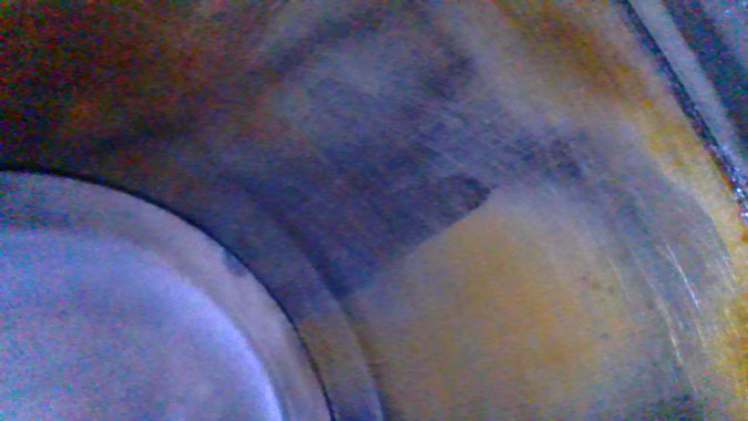
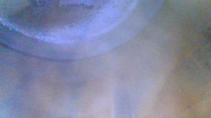
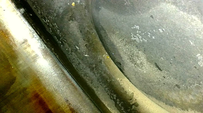
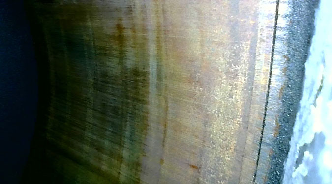
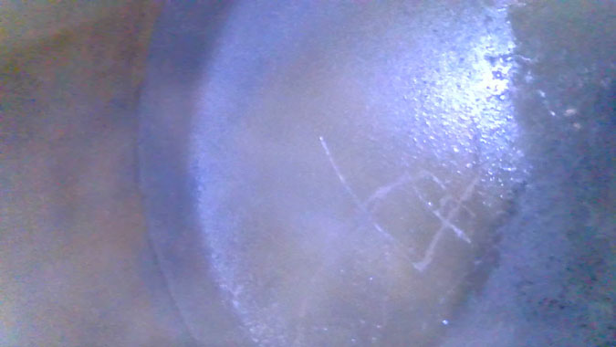
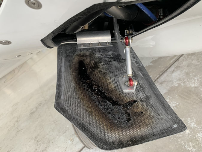
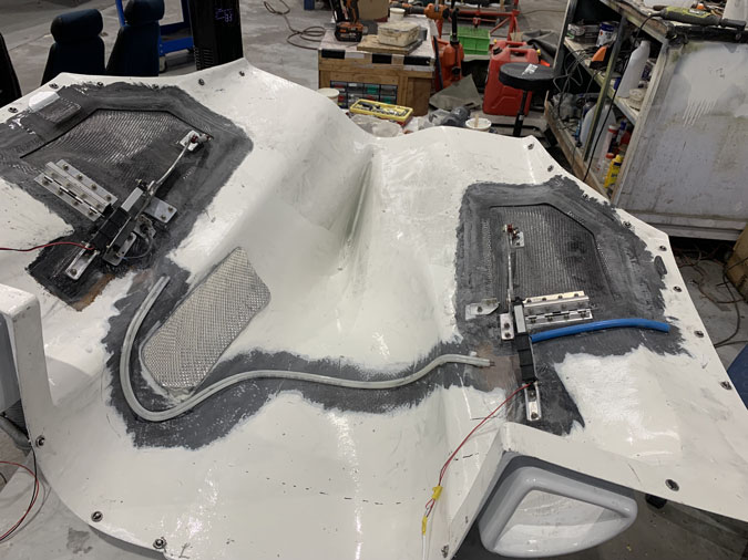
Well you can see what leaked out overnight.

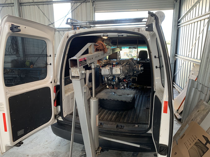
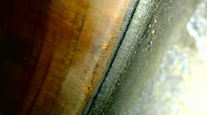
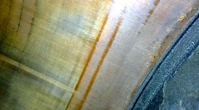
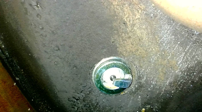
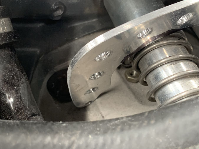
On investigation and some research it looks like the O rings in my water pumps have failed. I never touched them during the reinstall and they didn’t leak before. The idea fits perfectly with them run wet for a while and then the coolant drained and the system dry for over 6 months. So I pulled the fittings and had to drive home again (1hr 45mts each way) after hoping to be close to flying. We have the weekend then a public holiday so I might get two little O rings mid week. I think there are about four other leak points. I’m not sure if just a tighten will do it but the O-rings are a game stopper.

Replacing those is not negotiable so that’s the next step. Then another run. Of course I need a ‘spotter’ each time to let me know if there are leaks or problems as I can’t see the engine from the cockpit. If the other areas are leaking, I may need to replace fittings. They have to be perfect in the coolant system compared to oil or even fuel. Water is thin! Wish me luck…


Engine Returned – So what Happened?

Date:  12-19-2025
Number of Hours:  0
Manual Reference:  23

As I explained in the post ‘‘engine-rebuild-1‘ the engine became so tight I couldn’t start it. Its been to the engine shop and lived there for five months. This puts my circumnavigation plans back until 2027 now.  First up they ‘pulled the jugs’ or in plain speak, removed the cylinders.

As it turned out the ‘bottom end’ of the engine was perfect, no rust, no problems. Nothing to see here. That was good news as I was expecting a bulk strip with a rusty camshaft and who know what else.

In the cylinders things weren’t too bad either.

A tiny bit of surface pitting but of no concern.

The bores only needed a light hone with the ‘dunny brush’ and the valves were no problem. This shot is after the work with a lot of preservation oil. The cylinders were not glazed either so run-in or break-in worked out OK.

Eeeerrrkkk!!

The rings however….

Huge amounts of rust at the rings, locking them solid.

Even after a clean up these are not so pretty.

There was also corrosion just at these intake ports but not down the tubes. It was confided just to the heads area.

New rings were of course required. These came from the engine builders in the USA.

They don’t seem to be a standard part, they are different to the old rings. The top ones have TOP 5.319 which would be the bore size. I have 390 cylinders, I assume bored out, and oversized pistons given they are marked with xx.

The oil rings have no markings. The following is what was sent to help the install and I’ve put it here so I have a permanent record in an easy to find place.

Here is some specs. *Cylinder base nut torque spec. Lube the threads and the matting surfaces of the spherical nut generously with Carrillo bolt lube I sent you I can take a pic for reference, use the Lycoming torque sequence but using our final torque value of 60 ft pounds on the 1/2″ and 32.5 ft pounds on 3/8″ studs. Make sure you torque wrench is 90° to the engine vertical centerline as its super easy with base wrenches and the higher value to cover torque as they are always in a awkward area its not near aa easy as a regular Lycoming.

*Pistons are directional I will send a diagram so you can confirm nothing gets flip flopped.

*Piston rings must be installed using a ring expander if you try to roll the piston rings on you will very potentially experience ring issue or micro welding as the ring side clearance is tight and the square ring desing will damage the groove, always oil the rings and grooves before install, make sure the ring rotates freely in the groove while compressing the ring slightly. Stagger rings 180° so staring at the piston the ring end gap will be top ring 12:00. 2nd 6:00 and then I do the oil at 11:00 or 1:00 just slightly offset from 12:00. Top Ring end gap. .029″-.044″ 2nd Ring end gap. .029″-.047″ (2nd ring should be .0025″ to .0045″ larger than the top ring gap Oil Ring end gap. Min .020″ These values fall in spec but for your build I would not open them up if they are above the minimum value and I already added .0035″ to the 2nd rings chances are you will not have to touch them but must confirm.

*cylinder honing notes. I don’t know if they need to touch them up but they can’t go too big on the cylinders they will have to check the dimensions. If they do hone they need to target for a rvk 80 and a rpk under 10 are the 2 most important values. Hopefully they have a profilometer maybe confirm with them so they can check surface finish, its very critical. One other thing to note the ring goes right to the top of the sleeve like .020″ from the top so very close there is an additional. 070″ of room before they crash into the head, they should have no issue with this unless their is a tooling clearence problem but its worth noting as its not typically how lycoming does it they normally have tons of room. Piston to cylinder wall clearence is .0065″ to .012″ If they struggle on the hone we could always resleeve your cylinders if needed.

*A thin base shim gasket was shipped that will be installed on the cylinder first then your standard lycoming o-rings. The engine deck surface and cylinder surface must be extremely clean and dry before install, a grey scotch brite pad is ok to clean up little scratches or debris, teeat it like a automotive head gasket instal no nics or high spots, from scratches, ect. Clean and dry. Will send pic for install reference.

*Cylinder install. We need to talk about this before done as very critical and easy to mess up critical components if not done right, I can discuss procedures that will make it easier and less likely to cause any damage but here is overview so you have an idea of what is required. when installing the cylinders on the plane we will talk first. During the procedure its very easy for the cylinder to rick and for the skirts to hit the studs so extreme caution is needed, but need a smooth flat surface that is level to the crank and can set height right (I can send pics and will discuss more as this sets you up most for success, failure, or just pulling your hair out! Lol), remove the lower coolant fittings with the 2 allen bolts so it sits flat on the surface, load the pistons with inner clips already installed and push them in to wear the wrist pins can slide in still in the relief cuts so once the oil ring is in just a hair further, the rotate the engine to where the rear ro is highest up then install wrist pin and clip, rotate so you instal the front wrist pin and clip then push cylinder on and follow lycoming torque sequence for thru bolts not single cylinder. (Can send diagram for sequence if needed) Thanks and keep me posted and I will send you a few diagrams on the torque spec, piston orientation, etc.

These are the instructions verbatim. Nothing further was sent. The engine shop back here in Australia were happy to go ahead and are very confident the engine is correctly back together.

I was very please to get the engine back to the van for transportation. It was a mammoth day with 10 hours driving to get it to my hangar.

I mowed the lawn on my last trip, so this is 5 months growth while the engine was getting a new set of rings. The shop here have great people and do quality work but they can’t find more staff so things take a crazy amount of time to get done. I am both grateful and frustrated at the same time.

Back to business, the reinstall is proving to be an enormous job with a lot of challenges. I’ll update all this in another post.

What happened to the engine? Why did the Rings rust?
Haaa we are finally here. Water causes rust. My coolant level hasn’t moved during the test flying. There are no cracks in each cylinder  and they all had similar amounts of ring rust. This rust is confided to the heads.

The rust got WORSE the more I flew. That’s crazy. It got so bad that the engine became harder and harder to start until is didn’t. The rust was stopping the rings from moving and they were catching in the bore as I tried to crank the starter. No dice.

A borescope confirmed terrible rust after the ‘no start’ that was not present at the beginning of the test flying. I did a check before the program began. We had a little surface rust initially but it diminished with ground runs and a couple of oil changes and filter cleans. I was always concerned about the engine tightness from Day 1, perhaps this is not the worse thing that could have happened.

Condensation! (or Sweating)
Yeap. It must be producing water from the atmosphere that runs down the cylinders and collects on the rings. For ‘break-in’ I use Aeroshell 100 straight mineral oil and that has no ‘detergents’ or rust inhibitors, so we have no corrosion protection either.

I believe when warm, moist air comes into contact with a cold surface, the air right at that surface cools down. Since cooler air can’t hold as much water vapor as warm air, the excess moisture condenses into liquid water droplets on that surface. As best I can tell it depends on the dew point or humidity at the time as to how much or little temperature difference (DeltaT) can cause the problem. Probably around 20-40F gap would be enough to give me this very expensive situation. That’s not much at all.

With my cooling flaps open after landing, given under the cowls would be heat soaked, I now produce a rapidly cooling surface while my coolant at 160-200F stays much warmer. So I get a temperature mismatch. My rapidly cooled external cylinder surfaces drop below the dew point of the surrounding hot engine bay air = sweating. 

This also produced the 5 month gap in my program (as I keep saying) and I’m already another month gone in getting the reinstall started. I might be flying again in February 2026. Then I have to bed the rings in which might be 20-40 hours before I can resume the test program.

I think I might leave the cowl flaps closed after landing now! Maybe lean out the engine then and be in no hurry to shut down. Its a plan. Once the run in is completed I’m thinking Camguard oil additive might be good too when I go to the Aeroshell 15W50 Oil or something similar.


Solving Ground Cooling 13 (the Locks!) – Update

Date:  09-13-2025
Number of Hours:  29
Manual Reference:  no ref

Since the first flight there has been a problem with the flaps opening uncommanded. Not all the way open but initially it was about one third, causing a lot of drag. There was no failure in the flap mechanism which was still tight, just enormous air pressure inside the cowl.

The original actuators had 16lbs of force. That seems an awful lot when you test it with a fish scale. Well, not enough so I upgraded to 38lbs of force. This is the most they make in the exact same footprint. FA-MU-36-12-2 (38lbs, 12volts, 2″ stroke)

You think that would have done the trick? It did improve things but the flaps would creep open several times a flight. Just a little bit. The actuators work on electronic stops, not mechanical. We think they were back driving in flight and cycling the flap switch would get them to close instantly. Then a bit later they would crack open again.

The drag caused was enough to change the sound of the engine and closing them again would slightly alter the deck angle to a little flatter. If I even get in an emergency situation, opening them right up would be like airbrakes! They are not designed for this as thin carbon cowls do not have strong hardpoints to mount a serious flap for regular use. I’d want something attached to the airframe and that would be another can of very heavy worms.

After a lot of thought, including some ways of doing this mechanically with levers, the decision was to go for a little solenoid latch. It needed to be as fool proof as possible. Imagine if the latch doesn’t open properly, the powerful flap comes up and breaks off the latch, it ends up in the prop and I have a really bad day.

What I needed was something with an angled moving tongue and a bit that sticks out the back. The rear is to trigger a microswitch. Then of course something really clever to wire it all together with the least failure modes.

These are unmodified solenoids (no rear bit) In the middle is ideal for a latch to hold the flap but that right over the exhaust pipes and these solenoids are not rated for a high heat environment. So they are probably destined to sit on the side, have a heat shield and wrapped in insulation like the actuators. In the pic, I’m just trying out positions and thinking, one latch per flap will be enough.

Of course I couldn’t just buy what I wanted and ended up with several sets of these little solenoids. Remember I wanted the angle, the bit poking out the back and some sort of bracket as well to fasten them.  In the end two different ones looked like they could be cobbled together.

A bit more thought was needed on how to mount the microswitch. We want the solenoid to be able to tell the flap actuator we are ‘unlatched’ before it can move. Like a condition of exit. Then for closing that angled tongue would retract automatically as the flap comes down, no extra power to the solenoid needed. When powered it retracts, the tongue is on a spring, like when you slam a door. It will lock you out and close hahaha.

On the ground it would be opened, so that’s when power to the solenoid in needed, if I had a problem better then. For closing just before take-off, it needs what we already have just the flap closed and if everything is lined up correctly it should latch. Then to open, we are back on the ground again. This way seems to have less failure modes.

I used a bit of cardboard for proof of concept and then off to the welders.

Welding was very successful, he knows what he is doing for a tiny job like this. No big blobs to file off. I did previously modify the cases as the wires on our hybrid unit were exiting the coil in an inconvenient spot.

Here’s the unit with the microswitch, it can tell us when it is engaged. I had to play around a bit with screw holes and things. Its not pretty but we got there.

The four units are now assembled. Of course they weigh ‘something’ and I hate that but this problem needs solving.

While discussing the ‘how’ with my electronics friend we wanted something that we could just wire into the cowls passively. No relays and no extra wires running to the cockpit. We are both a bit over that. The above is the ChatGPT solution which was a starting point for me to make some sort of contribution. It was what was already percolating in a better brain than mine.

I tried to get it integrated into our existing, perfectly drawn circuit diagram but that was a big fail for the A.I. You can see a little mess in there three switches down. Maybe the next version will do it correctly. If anyone is crazy enough to do these flaps and needs the proper drawing, done by a smart human (not me!), just make contact and I’ll send the good copy along.

Next up we need to do the wiring. These are approximate spots for the latches. I’m not going to set it all up before the engine is back as there will no doubt be a gotcha and I’d have to move things an inch and make a big mess in the process. The striker plates or key holes can’t be done until then either. I suspect that each latch will need a different design depending on where and at what angle the unit sits.

Well the engine is back, we are mid January 2026 now! I thought I should tackle this job so the cowls were ready before the engine was in case I had holdups. I did of course and I’d damaged one of the solenoids when fitting the cases, so more had to be ordered from Europe. <sigh>

Each lock needed careful fitting. The latch ‘just’ catches as it also need to move out of the way for the flap to open. There is not a lot of movement in the small actuator for the tongue to pock out.

I have protected them from heat as best I can. Unfortunately the lock part has to position closer to the exhaust pipes than I like. We will see how they go.

This is close to the final set up. It was as usual too much work and took too long. That’s just the nature of this project and when doing something a little different.

https://alongwayroundtheworld.com/wp-content/uploads/2025/09/Flap-lockupgradeEmail1.mp4

This is a low res version but still a bit big for a website video. It does give you a look at the flaps in operation.

Just to show you… there are now a LOT of fasteners on these cowls and I had to add a lot of weight. I’m not happy about this side of the work but I do think the ground cooling problem is solved and hopefully the in air cracking open of the flaps as well. Fight testing will tell the story.

Engine Out and Moved

Date:  09-18-2025
Number of Hours:  16
Manual Reference:  no ref

Removing the engine for its bulk strip was, as expected, a big job. Unlike air cooled and a basic magneto and carb engine, this one has a lot more things hanging off it.  July 6th 2025 I made the decision, or rather the engine told me, it needed a proper doctor and serious surgery.

These shots are with things intact.

During removal I took around 200 photos. Just close ups of each item as I removed them.

Along with the photos I have 6 pages of notes. This will give me some kind of order for the reassembly as well as a few things to watch out for.

A lot of work went into making these things fit. Clearance to the cowl is around 1/4″ in places.

One thing I will be doing is replacing that Laminova unit with this longer one. I ‘think’ it will fit but the install will be a challenge. The brackets took me about a week last time to figure out and fabricate.

All over the hangar are boxes like this now full of engine parts.

It was easy to get off the plane once every thing was removed. Of course there were a few hidden things that needed undoing. Going back it I’ll have to have the engine not quite on the mount and add a few pipes and bits before seating it in place.

All out. Kind of sad after so few flying hours. Going back in might be a couple of weeks work instead of the four days to get it out.

I never thought I’d need this engine hoist I bought for the initial install…again.

This is the VW van I have borrowed, a perfect size for this job. It wasn’t available for a few weeks after engine removal but it didn’t matter as the engine guy was away in the USA.

This is in Cobram, Victoria loading it onto ‘the floor’ at the engine shop. It’s about 350km from my hangar. It was seven hours on the road that day. It would take around 1 hour by air if the engine was happily in the plane and I didn’t mind using a bit of fuel. Driving, compared to flying, may not be my favourite thing.

Now I wait….

Engine ‘Rebuild’ 1

Date:  07-12-2025
Number of Hours:  0
Manual Reference:  23

My new AC-Aero Gladiator LIO-390 engine has had 30 hours of flying. It now needs to be removed and sent to an engine shop. Maybe a bulk strip, which is effectively where the engine is disassembled with the case split open and parts are inspected. Until they look pull the cylinders off we won’t know. At a minimum I will need a new set of rings.

Here’s how things look before I start pulling items off and remove the engine from my plane. It is not going to be a small job.

As it comes apart I will be taking a lot of photos and writing myself notes. Yes, its going to be yet another journey. My plans for round the world next year might have to wait until 2027!

What Happened?
Good question. Lets start with before the first engine start after getting everything installed on the plane.

https://alongwayroundtheworld.com/wp-content/uploads/2025/07/Engine-groans-22_9_24-small.mp4

You can see or rather hear there is a bit of groaning going on here as I slowly pull the prop through by hand. This engine is tight. This is way back on 22nd of September 2024.  I was told at the time by the licensed guys in the hangar that this sometimes happens with newly overhauled engines, it usually resolves in a few hours of flying in their experience.

You are looking at the inside of my cylinders.

Yes, that yellow colour does not mean I have gold plating.

I was still worried about my groaning powerplant so I bought an endoscope for looking inside the cylinders. They are usually called borescopes for engines but this is what was on the box. Anyway the cylinders were full of rust!

What happened?
It turns out that my engine was delivered without preservative oil. Something conforming to MIL-C-6529 Type I is the norm. Now to be fair, I’m sure they did put a small amount of preservative in it, probably from a spray can. This is mentioned in the log book. The engine did have desiccant spark plugs which is the cream on top.  Another factor is that the engine is not meant to be full of oil when shipping to Australia from the USA. Maybe this is why nothing much was inside to prevent rust? It was a good 12 months that I spent putting the thing on my plane before we found this problem.

OK, should I have thought of this? Well you’d think I’d get a heads up from the engine builders if it was sent with just a spray of inhibitor and nothing else. It is standard practice to inhibit any engine that might be sitting around for more than a few weeks. I would no more check that this had been done than I would check the wheel nuts on a new car. I did not check every exposed nut for correct torque either. I put inhibiting in this category. All this time I was in a hangar with professional aircraft mechanics, it never occurred to them either. Why check for something that is always done as a matter of practice. So still my fault? Yes, I’d say so. I should have been totally paranoid about rust and done the job myself.

What next?
On advice, I changed the oil again, checked the filter and ran it for a few hours. Then I got my endoscope out, had another look and changed the oil and filter again. There was less rust the second time although definitely rust particles in the filter. Same again, I ran it for a few hours and did the filter, oil, endoscope. Well, less rust this time and short of pulling the cylinders I kept going with the taxi tests and then flying.

I do have to say I had numerous problems with the delivered engine some of which are documented elsewhere in this blog. Compression were very poor (although to be fair they were done on a cold engine) and it took a long time to get it tweaked so it would even start.

What happened next?
I did my first flight and another 30 hours of the test program. I had it starting on the first try for a while but it became progressively more difficult. The last few flights needed 3 tries to get a start. Finally I just could not start the engine at all. The tightness when pulling the prop through had continued as a major concern to me. It wasn’t right but I was flying and it seemed to run well once it was going. The fuel map was all over the place but that can be tweaked manually.

With the no start I did another 6 teeth on the flywheel and had to get the ring gear replaced. Ouch. I had some great advice from a USA engine guy and tweaked the timing to ensure zero TDC (top dead centre)  for the start. All back together it still would not start and this time I didn’t ‘push it’. The previous start failure had kickback which caused the damage. This can occur with the voltage low. My batteries are quite new and I have them on float between flights. I started pulling the prop through as a check and it was tight, really tight.

OK this might explain the no start. So much friction that I can’t get enough rotation speed? I had replaced the sparkplugs since the last attempt and this time they didn’t even get to fire. Here comes some videos so you know what I mean….

https://alongwayroundtheworld.com/wp-content/uploads/2025/07/I5_7_25-full-through-tightSM_WEB.mp4

You can see how tight the prop has become (plugs in).

https://alongwayroundtheworld.com/wp-content/uploads/2025/07/I5_7_25-top-plugs-outSMWEB.mp4

Here with the top spark plugs out we should have the thing spinning pretty freely. Nope it is still tight.

https://alongwayroundtheworld.com/wp-content/uploads/2025/07/I5_7_25-top-plug-out-30minutesSMWEB.mp4

Of course the engine is cold because I couldn’t start it. I went for a ‘better’ video 30 minutes after the last one and the prop is now much looser. WTF???? I believe something has moved inside the engine given it now has reduced friction. Time for a look inside….

#1 Cylinder


#2 Cylinder

#3 Cylinder

#4 Cylinder   I’ve put a lot of photos up I know. Maybe someone will look at these and add some knowledge from their experience. Either way I have to do the obvious.

What Next?
With a no start and this cylinder inspection the decision was easy. The rust has increase enormously with flying and running the engine. It only used 1.5 litres of oil in 30 hours as well. The cylinders are just not getting lubrication. The oil rings are not doing the job and give the intermittent tightness something bad is happening deeper in the engine.

I have arrange for an engine shop to do a ‘bulk strip’ if required. Unfortunately they can’t look at it for a couple of months. That does give me time for removal and transport. It’s about 5 hours away by car and there are some logistics to deal with of course. Once we have a complete inspection we will know what needs doing and go from there.

I was never happy with the engine as it was delivered. There were too many things pointing to problems down the track. Fortunately perhaps, the issue has occurred requiring very major work. On the other side of this I will move forward towards my goals with increased confidence in my ride.

Rudder Pedal Refit

Date:  05-26-2025
Number of Hours:  16
Manual Reference:  13-8

The rudder pedals needs adjustment. They are too close and my knees hit the top of the Instrument panel bulkhead when I move to place them on the pedals. Part of this is probably because I moved the front seat two inches forward in the build for CofG reasons and the fact that I’m not a tall guy. Probably a mistake given this issue. Then again I do sit quite high up with my modified canopy so its likely the problem would be there anyway.

Here’s the position I need to modify. I thought I’d just have to extend the cables via spacers but this turned not to work and I needed a different solution.

I made up an ice-cream stick mock up which seemed to be about right.

Then I carefully tested it in place.

Just to be 100% sure, I had a couple of pieces welded on so I could test different lengths using a bit of foot force in the cockpit. I might mention it is a whole world of hurt installing and reinstalling the pedals. At one point I had to remove the whole nose gear leg and actuator to get to the embedded nuts as one was suspect.

No it was me that was suspect, I just needed a longer bolt to properly engage. <sigh>

I had them beautifully welded by a buddy in the next hangar who just happened to have a stainless steel welding business in town. About time I had some luck. I spent a few hours installing them with my head upside down at times. It was a lot easier before the panel went in.

Of course after testing I still didn’t have it right, despite being really careful. This is the final result, version 2. It works, but it is not ideal. Maybe there is a way of angling the pedal rods or something.

They are useable and I’m going with them for now, and probably for a long time. I can taxi, brake and sideslip in to land OK. I’m just surprised that I couldn’t get it spot on. I think this is still down to the panel cut-out heights and the seat position.


Repainting the Cowls

Date:  04-16-2025
Number of Hours:  35
Manual Reference:  25

Time to repaint the cowls…again. They were done beautifully the first time. Then I had to lose a welsh plug and they were heat damaged during taxi testing. Next up I decided I had to add four huge flaps for ground cooling. That make a bit of a mess. Then I did a taxi test with insufficient heat shielding, that further cooked a few more bits.

The first job was to address all four flaps and improve the ‘intersections’ where they met the cowl openings.

This was a two step process where I would work on the cowl side with filler and get the intersections right and then the flap side with the same thing.

Of course this meant a lot of sanding. I little with the air driven tool but plenty by hand too.

I did a lot more sanding than you can see here. I spent days getting them ready for paint.

Of course my efforts were not enough. Once the first lot of primer went on, the paint started to bubble. The heat damage must have really upset the lower layers. So my expert, Jamie, pictured here, spent 51 hours getting it right. That was with a lot of sanding and filling before the primer was again introduced. Then more sanding.  She is even fussier than me. I can put that work in but I don’t get the same results. Some people only have one standard.

Perfection is the enemy of good enough and no prisoners were taken on this job.

They really are as good as you will see anywhere now.

No polishing, this is straight off the gun.

After the cowls came back I had quite the task to reinstall the hardware. It was three long days. All the edges needed to be addressed where the cowls close as well given a little paint build-up had slightly effected the flap closing.

This might give some idea of the quality of the paint work. Yes I know I used a lot of fasteners. There are a few things I would do differently next time. One would be to take the hardpoints all the way to the skin rather than leave a little foam. I was worried about all the extra weight but you can see slight depressions where I have to tighten things up in some places.

The insides were also painted again, not with the super high quality and insanely expensive paint, but a good two pack white. This is mainly so where oil and grime builds up I can see where leaks might be and do a good clean up. This time I was meticulous about adding heat shielding afterwards where the exhaust pipes are near the cowl surface. The bottom cowls had a similar treatment. Even the actuators have full heat shielding to protect the mechanisms.

An unrelated shot, but I did want a record of this. People say the Long-EZ is a small airplane. The wing span is 26’2″  while an old Piper Cherokee is 30′. Just under a four foot difference, a relevant fact when you need hangar space.

The top cowl is finally on.

Both cowls and the baggage pods are now installed. This shot was a couple of days after the first flight. The second test flight had the pods on.

Finally an innovation I stole from James Redmon’s Berkut build. There are some great mods on his pages.
Yes, its not related to the cowls, just one of so many little things I’ve been doing lately that don’t get a mention.


RTW Route East #12 rev2

Date:  04-08-2025
Number of Hours:  0
Manual Reference:  no ref

My route for this first Round the World flight keeps changing as the world situation does. I’m also getting great information from three ferry pilots in particular and internet searches on fuel availability, airport charges and places with ‘customs’ or ‘ports of entry’ for international flights. This update has valuable suggestions from ‘Ross E’. Thanks!!

Here’s a flat earth overview. Each ‘kink’ is a single flight, 21 in all.

If the earth is round after all, the lines don’t look too straight.  This view shows the ICAO airport names that I’m currently planning on.

Nov 3 ’25 – A little change here from Howard (KHWD) to San Luis Obispo County Regional as a point of entry into mainland USA. I’ll update the map graphic later. The previous plan had me flying through Class B and passing several airports. I’m running flights in XPlane and discovering interesting things!  I looked at some coastal options but given landing late in the day, I could be risking fog. Sure, there will be an alternate but I’m thinking I want a towered airport and a minimum of potential challenges after a 12 hour plus flight.  I’ll add that current engine issues will probably delay me a year. Everything needs to be very well tested and I have to be satisfied that I’ve found as many gremlins as possible.

That does look all over the place!  Here are some rough numbers (that I will be adjusting later) based on a conservative 170kts and 35lts per hour and nominal winds which will change. I do hope to get much better numbers which I will know after more flight testing.

Flights

YMMB YSNF
Moorabbin to Norfolk Island  1,303nm, 7hrs 30mts, 339lts,

YSNF NSTU
Norfolk Island to Pago Pago, American Samoa. 1,320nm, 10hrs 8mts, 254lts

NSTU PLCH
Samoa to Kiribati, Christmas Island 1,265nm, 7hrs 34mts, 312lts

PLCH PHKO
Kiribati to Hawaii, 1,063nm, 7hrs 51mts, 199lts

PHKO KSBP
Hawaii to San Luis Obispo, 2,133nm, 12hrs 40mts, 483lts

KHWD KSAF
California to Santa Fe, New Mexico, 938nm, 5hrs 39mts, 206lts

KSAF KMKL
New Mexico to Tennessee, 857nm, 4hrs 51mts, 206lts

KMKL KMRH
Tennessee to North Carolina, 607nm, 3hrs 23mts, 148lts

KMRH TXKF
North Carolina to Bermuda, 618nm, 4hrs 10mts, 110lts

TXKF  LPAZ
Bermuda to Santa Maria, Azores, 2,039nm, 11hrs 13mts, 398lts

LPAZ LEST
Azores to Santiagio, Spain, 849nm, 6hrs 4mts, 248lts

LEST LMML
Spain to Malta, 1,225nm, 6hrs, 25mts, 248lts

LMML HEGN
Malta to Hurghada, Egypt, 1,332, 7hrs 48mts, 324lts

HEGN OMAL
Egypt to UAE, 1,193nm, 6hrs 41mts, 243lts

OMAL VANPI
UAE to Nagur, India, 1,313nm, 7hrs, 58mts, 364lts

VANPI VCBI
India to Colombo, Sri Lanka, 833nm, 4hrs, 45mts, 174lts

VCBI WMKL
Sri Lanka to Malaysia 1,186nm 7hrs, 255L

WMKL YPXM  Christmas Island (Australia), 1,064nm, 6hrs, 36mts 255lts

YPXM YPPD
Christmas Island to Port Hedland (Aust. Mainland), 955nm, 6hrs, 218lts

YPPD YNUB
Port Hedland, WA to Nullarbor Roadhouse, SA, 936nm, 5hrs 22mts, 196lts

YNUB YMMB
Nullarbor to Moorabbin, VIC 820nm, 4hrs 31mts, 193lts

21 Flights of about 26,000nm (48,000km) and about 5,400lts of fuel

First Flight

Date:  03-24-2025
Number of Hours:  0
Manual Reference:  

First flight of my scratch built Long-EZ, VH-XEZ, happened on the 24th of March 2025. 13 years 3 months and 23 days to be exact after starting. My log shows 17,044 hours of work. This is not counting meal breaks, sleeping, time thinking about it or running around doing plane related things. This is just time working on the build in the workshop.

I’m not proud, or ashamed of this enormous number of hours. I started with very high standards and almost no skills. I’d never done fiberglass work, I couldn’t understand the plans and I’d never done anything like this before. I’m not an engineer in any form or have particular skills in the workshop. I did guitar setup work and basic repairs for a long time so at least I had some manual skills. Measuring anything was pretty much something new as I used to do everything more by feel than ‘science’. I had a lot to learn.

The big time soak was that I already had a ‘plans built’ Long-EZ I’d done a few minor things to it but I wanted something a bit different this time.  A few months after starting, my brief changed from the idea of a light weight, high performance Long-EZ to a round the world, very high performance extended flight vehicle.

This meant…..modifications. NO modification goes unpunished in terms of time and expense and this one got out of control. I needed the qualities of DR Who’s TARDIS to fit everything in, a Long-EZ is …small! Unfortunately my skills in compressing spacetime are lacking, so it took a while.

https://alongwayroundtheworld.com/wp-content/uploads/2025/04/First-Flight24_3_25-email-resolution.mp4

Here’s the first flight video. Its very low resolution. There is a better version on my YouTube channel.

So what was it like to fly this thing I have built for the first time? What happened on the 24 minute flight?

I’m usually nervous before flying. It ranges from almost no nerves if I’m flying several times a week to quite a bit in direct inverse proportion to when I last flew. Once I’m all set and taxing off I have zero nerves for the rest of the flight. The only exception is flight instruction and particularly flight tests, I’m not good at all for those! <grin>. Interestingly I’ve had several emergencies over the past 40 odd years and I’m just ice cold and get the job done every time so far.

First flight nerves just felt like any other flight, relative to the time since when I last flew. Nothing special. If anything it was a bit disappointing to not have the feeling others talk about. I’d already had the canard fly very briefly in a taxi test. That was important as I needed that confirmation before committing to extended full throttle.

Canard rotation was as the taxi test in the 60 knot TAS range. Also as testing there is a slight pull to the right on application of full power on the initial ground roll but its gone in a second, I just needed to be ready for it.  I was more focused on the runway position, how much was left if I have to reject the take-off,  than the ASI and the just focused on feeling the aircraft. I knew there was an issue with the static port position and that IAS was going to be about 10 knots over. I had to use more back stick than expected to get the canard up. I did have the trim with elevator down already but it needed a bit more. Full rotation needed more positive pressure than the last plane. This may be just the trim.

I was pretty quick on the hat top trim adjustment which proved to be incredibly sensitive. That was ‘fun’. I’ve since adjusted it in the G3X and we will see how it is next flight.

Pressures and temperature here were excellent. My concern was that this plane wouldn’t cool in the air, and I’d have to modify the cowls so that was a big one. I’d fixed it for ground taxi with the flaps, flying was unknown. So far we are good. The plane was flying very well and the handling on this initial flight was excellent. It had a super smooth roll. Pitch is very sensitive, partly due to the trim not being perfectly setup yet.

Climb was off the charts, nearly 170 knots at 1000fpm. I had a lot going on. For some reason the second radio was loud and active despite not being selected on the audio panel.  This is weird. I tried changing to to another frequency but there was chatter on that and then a lot of static with another try. Meanwhile fainter, Moorabbin tower was in my ear concerned at my climb. I assume and worried I might bust into Class C above the field. I should have just turned Com 2 down but I wasn’t familiar enough with the interface and didn’t think of it anyway. I can’t reproduce this on the ground so it is a matter of trying again in the air. I need to be ready to get the volume down next time that’s all or just set it to Com1 frequencies.

Meanwhile there was an alarm going off in my ear. This turned out to be the canopy warning when I finally focused on it. The canopy was locked and ‘pinned’ so it must have been the micro switch needing adjustment. I’ve since tweaked that and we will see if it happens next flight.

More alarms were happening. The cowl flaps despite being closed before take-off both upper and lower were showing open. It turns out there was enough pressure in the cowls to blow them open to 1 out of 6 graduations. So just cracked open a little. I have since tightened them. Easy job as it was built into the design just for this issue. I do know that I can open them a little in flight and they wont break off. Unintended test! I had the coolant pressure alarm going off too. That one is just needs a re-calibration of the warnings. I wasn’t concerned about that as the number was still good.

Despite selecting gear up on my early climb out, the nose gear was down. You can just make it out in the picture. That was unexpected as it causes a lot of drag which I didn’t even notice. The cockpit video shows the selector is up but the gear has an auto extend, and that was operating. I tried cycling the switch but that did nothing. Better down than stuck up! This one is still to be sorted out. I think it might be either the laser needs calibrating for 100meters auto-extend or a micro switch is not actuating or both.

By now I saw some EGT warning showing they were high. Opps, I was still at full throttle. This would explain the insane speed in the climb. So we know that coolant and oil temperatures are OK in this condition. I reduced throttle and the exhaust temperatures dropped quickly.

By now, which is less than 5 minutes I’ve got the throttle back, ensured I’m under 2500′ and at least silenced the canopy warning. The radio is still annoying. The gear is still down, flaps showing open, pressures and temperatures are good. I tested rolling gently left and right. It takes more stick forces than I’m used to but it is very stable. I tried steeper rolls and was all good. Yaw is fine as well. Pitch is sensitive due to the trim speed challenge so I didn’t try to get to hands free. I just ensured it would be safe for controlling a landing.

By now I’ve switched to cockpit static and IAS is probably near enough to TAS now so I don’t have to subtract 10 knots from what I am seeing on the glass panel. That’s a bit different too as the old steam gauges are so big and easy to see instantly. I’m still learning where to look in a glance as a part of my scan inside and out.  I slowed the plane to 60 knots indicated and still no stall. This is enough for now I have the data I need for a safe, controlled landing.

The canopy and vision out the side windows as well as a slightly higher sitting position make the cockpit worth the effort I put in to the modifications. Outstanding result on that one. There is no spot for elbows in strakes however but I didn’t notice this as an issue. I know I’m going to miss cockpit storage that I could easily have added. I did plan on it but just forgot! Well, next lifetime. I don’t have another plane in me.

You can see I just hung around the airport. I did stray a bit more to the east than I planned but at 2500′ AGL, well above circuit height and ATC didn’t seem too upset about anything.

After a bit under 20 minutes I called up tower to come in. I might have given them an ops normal but I don’t think they cared. You can assume if there was a problem I would tell them. I was told to join downwind for 17R. I had a bit of height to loose and managed this OK while keeping the speed under control.

Landing was like all the other times I’ve landed a Long-EZ over 18 years. The difference was that I’m a little higher in the cockpit now, visibility is even better and for this first one I knew there was a phone video running so it had better be a good! I just set it all up, looked up down the end of the runway at the right time and just waited, holding the nose. If you watch the video you can see it worked out OK.

The taxi back to the hangar should be a time of elation, satisfaction a great sense of achievement, the greatest day of my life? Naaaaa nothing. Sorry. This has been so long coming that it was just something to get done so I could move on. Its about 3 years after when I though it would happen. Covid and engine delays were not my friend. Not to mention the huge job the ground cooling was needed when I though I was nearly ready. That added a  good 4 months at 70 hours work a week to find a solution.

Overall I’ve built a plane, it flies. There will be a few more weeks work to rectify some ‘squawks’. Then one more Moorabbin local flight to check the rectifications. If all is well, the next flight is leaving my home at Moorabbin for the new base and the next chapter in this adventure.

_______________

I will tell you one thing that has happened over the course of the build. I didn’t know much when I started and now I know more than I used to.

I couldn’t visualise mechanical things in my mind’s eye. Now I can think of the details of a modification and see possibilities and various angles, I can rotate an idea in my mind. My thinking on everything I approach in life has refined. I look at problems differently. I can see solutions to things I never saw before. There is a new focus. I have adopted a more ‘scientific’ approach to situations that come before me. I can see how to make things like I never could, devise methods for a repair or a part that I never saw before. I have a rare confidence that if I need to make something, I will just figure it out as I go along and not worry at all that it won’t happen.

I know that if I persevere, eventually, the solution will feel right and that’s the one that will work. I can go into something like the flap design and just push and push until it works out. I have a large box of prototypes on that to prove it. I might not see how at first, but the answer reveals itself, I just have to keep going.

Aeroplane building might surprise you with what the process it teaches. I now have to apply this to IFR flying and all my concerns and fears about not being able to succeed in the round the world task, the big airports, the pressures in the air, the procedures, the physical dangers.  Yet I don’t care about self doubt, that lives on a shelf I no longer look at. Plane building without skills just teaches I only need to get on with it.

Have a goal, make a start and the magic happens in-between.


Exhaust Wrap and Heat Protection

Date:  03-18-2025
Number of Hours:  16
Manual Reference:  no ref

“Just when you thought it was safe to go back in the water…” to quote Jaws. I did my first runway test, flaps closed of course and something got hot. 

Guess where the exhaust pipes sit?

Both sides on the bottom, right next to the pipes.

Of course I should have thought of this. In fact I did previously. Before the flaps were cut out I had heat shields here which were removed for the cut outs.  In previous testing I never got to high RPM for any sustained period so the issue wasn’t present. It just wasn’t on my radar until this happened.

The epoxy had boiled off and just left the burn marks. I dug it all out, which turned out to be huge holes until I got to good carbon and epoxy. The next step was to fill it with dry epoxy. Just pour foam would have been fine too, and a bit lighter. Anyway I followed up with three graduated plies of carbon and as you see above, good as new, move on.

I’ve added heat shield as I should have previously. The actuators also get a covering.

I’ve added lockwire to the hinges as well. Its hard to spot in the pictures. I got to learn a bit more about drilling small holes in thin aviation grade stainless steel too. The local tool shop is somewhat richer after my lesson included the purchase of quite a few very small drill bits. The local sheet metal guy eventually took pity and schooled me.

Of course this heat shielding will have to come off when I repaint the cowls. I’m trying to order some high tech shielding that is super thin. This stuff is closing the gap on the bottom cowl.

Not to leave things here, how about a thermal wrap on the pipes? I already have ceramic coating inside and out. This is in addition.

The wrap is relatively cheap and held on with stainless straps. Now I’m close to flying I hope the pipes won’t be coming on and off again for a while. This stuff is good for 1200C or 2192F. As the pipes get in the 1300F range I should a lot more heat out the back and less remaining under the cowls. I imagine my EGT numbers might be up a bit and the next runway test data will tell the story. Its looking like a good mod to assist with my cooling improvements.

Solving Ground Cooling 12 – Completed

Date:  03-14-2025
Number of Hours:  20
Manual Reference:  no ref

With the upper and lower cowl flaps now installed, the large avionics job remained.

After some planning I laid out conduit for wiring so that there would only be one plug for the top and one for the bottom cowl. The the carefully applied paint was taken back to the carbon and I hot glued the channel in place.

After it was fixed I went ahead with micro to transition the edges and properly glue the ‘pipe’ in place. Then a layer of carbon fibre over the top.

The top cowl just needed the one bridging piece for the wiring.

It then got the royal treatment from my wiring expert, definitely not me!

Somehow he put a huge amount of circuitry into the little box. there are eight relays in there! Not only driving the up/down signals but also hooking up to the four flap microswitches and one on the throttle to give auto retract if I forget them at take-off. There is also taking the signal from the flap position indicator and hooking that into the Garmin engine box. A huge amount of work. I just had to secure the box in the hellhole with clickbonds and do a few other ‘homework’ tasks.

https://alongwayroundtheworld.com/wp-content/uploads/2025/03/CoolingFlaps-14_3_25.mp4

Here they are in action. The wiring worked first try which was impressive.

They do look good.

WEIGHT
A total gain of 2.32kg (5.1lbs) incl. all reinforcement and hardware
Before the mods: Lower Cowl 4.14kg (9lbs 2oz)   Upper 3.37kg (7lbs 7ozs)
After: Lower Cowl 5.38kg (11lbs 8oz)   Upper 4.45kg (9lbs 8ozs)

The upper and lower cowl will need a repaint. Partly from blistering when I lost coolant during testing and these big cutouts for the flaps will need some transitioning work and edge rectification to make them pretty.

With a number of other small jobs done, I am ready for slow and fast taxi testing on the runway.


Solving Ground Cooling 11 – Upper Flaps

Date:  03-07-2025
Number of Hours:  110
Manual Reference:  no ref

Time for the upper flaps. I’ve been working 70 hours a week on this for some time and I didn’t expect things were going to get easier. Its just a matter of showing up and keep pushing. If you are thinking of cooling flaps for your Long-EZ, you have been warned.

This is where the top right flap mechanism has to go. Weaved in-between that stuff on the left side. There just wasn’t room on the right side of the opening.

As usual I start with ‘Masonite’ shapes and scrap metal.

That smaller shinny black pipe is in the way of everything. I managed to move it .5″ with different fastener positions. I could just remove it, but then the engine wouldn’t run.

I kept playing with shapes and putting the cowl on and off the plane dozens of times, it feels like hundreds.

https://alongwayroundtheworld.com/wp-content/uploads/2025/03/upperflaptest.mp4

One of the challenges is getting the geometry right so the flap opens a certain amount. Then its lots of testing.

All seemed ok so I could go ahead with the  hard point of .25″ marine ply.

The hardpoints get a ply of carbon to lock then in place although the fasteners really do that job.

Given it all seemed to work I made the main pieces out of my 2024-T3 aluminium and tested again.

The opening I want is 190-200mm which is what is happening with the lower flaps. This is not critical and +/-5% will probably not be noticeable.

https://alongwayroundtheworld.com/wp-content/uploads/2025/03/upperflapright.mp4

Everything seems to work.

Then for some reason, gremlins or evil fairies,  it doesn’t quite fit anymore and I’m ‘just’ touching in a couple of places.

So despite making a ‘finished piece’ it was wrong and I got to make another one, after some more prototyping, which is the finished piece on the right.

I got it all working, happy days. So on to the left side upper flap. It has to be easier? Hahaha …of course not.

The obvious spot for this left side was to put the mechanism on the inside to match what I’d done on the right side upper flap. There seemed to be more room too. This was going to be easy.

I made my usual bunch of prototypes and endless off and on to ensure it was going to fit. I probably spent 20 plus hours and got the push arms to fit, but I just could not make the actuator fit in the end. It was just too near the engine mount. This was a fail.

OK, I’m going to have to make it fit on the left side for this left flap. As you can see it just needs to fit around the engine and a few pipes here and there. On the plus side, there is heaps of room for the actuator.

It was getting weird but one prototype gets made, then acts as a template for the next which has ‘modifications’.

More on and off testing.

Getting closer.

This is nearly it.

I did make a nice metal one before this as I had it nailed. Wrong, nearly nailed doesn’t count so here’s the next one after two more Masonite versions.

This is quite pretty, like some strange weapon from movie.

https://alongwayroundtheworld.com/wp-content/uploads/2025/03/7_3_25Upperflap-done.mp4

This works. There is a bit of a catch in the door opening and closing to do with the cowl curvature that I will address.

The four flaps now done with a working mechanism. Wooohoo!

These are the prototype pieces that I made.

I don’t use CAD design and CnC cutters or plasma. I use MAD. Masonite Aided Design with a cordless jigsaw, drill, hand files and sandpaper.

I think this is more efficient as I can knock out a part pretty quickly. A final piece takes me around 2 hours and a few minutes for a prototype. It would be seconds with a plasma cutter…and days getting it set up just right and driving to someone’s place to do the job.  Then waiting for it to be done, then finding out its nearly correct and needing another one made. My own gear would be huge time and expense. I need it now!

Next up is to design some sort of flap alignment system as these guys are likely to move around when closing in high winds and they might jam open or at least be glitchy. I’m not having that!

They also need the electronics, which is being worked on.


CategoryLogsHours
All158917236
Ch 3 Education220
Ch 4 Fuselage Bulkheads25231
Ch 5 Fuselage Sides32283
Ch 6 Fuselage Assembly30270
Ch 7 Fuselage Exterior14140
Ch 8 Roll Over/Seat Belts990
Ch 9 Main Gear/Landing Brake71642
Ch 10 Canard28287
Ch 11 Elevators36298
Ch 12 Canard Installation12102
Ch 13 Nose and Nose Gear1301113
Ch 14 CenterSection Spar57525
Ch 15 Firewall and Accessories448
Ch 16 Control System27237
Ch 17 Roll/Pitch Trim System654
Ch 18 Canopy70502
Ch 19 Wings, Alierons1271090
Ch 20 Winglets/Rudders71528
Ch 21 Strakes - Fuel/Baggage65437
Ch 22 Electrical System591031
Ch 23 Engine Installation1001168
Ch 24 Covers/Fairings/Consoles25202
Ch 25 Finishing571119
Ch 26 Upholstry340
Fuel System46310
Rollover1050
Cabin heating System60331
The Ferry Tank335
Blog2764278
Nose Gear Doors856
Wheel Pants/Gear Leg Fairing40473
Oxygen System762
Roll and Pitch Trim964
Winglet Intersection Fairings445
Baggage Pods11104
Pilot Side Windows437
RAM Air & Hellhole Cover15177
Main Gear Beef Up322
Post Cure124
Fire Extinguisher16
Wing Fences13
EVS (Enhanced Visual System)130
Hinge Upgrade115
Cowl Keeper110
Rudder Gust Locks19
Cooling21636
Taxi Tests42
Flying10

Bedding in New Rings

2026/04/17 10:26:01

Round Australia in Four Flights

2026/06/17 10:26:01

Round the World Departure

2027/08/22 10:26:01

Rough River Flyin, Sept 23, 2026

2027/09/23 10:26:01

© Copyright 2026 Dave Berenholtz