| Date: 02-15-2018 | |
| Number of Hours: 5 | |
| Manual Reference: 12-1 |
This is a modification of the modification! Instead of a pin we have a long bolt. Now I’ve decided to reverse which end is the bolt and which the nut plate. Why, do you ask? I’m now going with a removable canard cover, I wasn’t sure before. I need to reverse the nut/bolt combination because once the instruments are in it will be very hard to get the bolt out from the IP end. So that mandated the cover being removable too.
For the one or two people following my progress there has been no post for a week or so. I’ve been working on circuit diagrams and learning enough CAD to get them into .dwg files. Just the main drawing done now and I’ve gone a bit sideways looking at external lighting and throttle switches. Its good to be back mixing a little epoxy again.
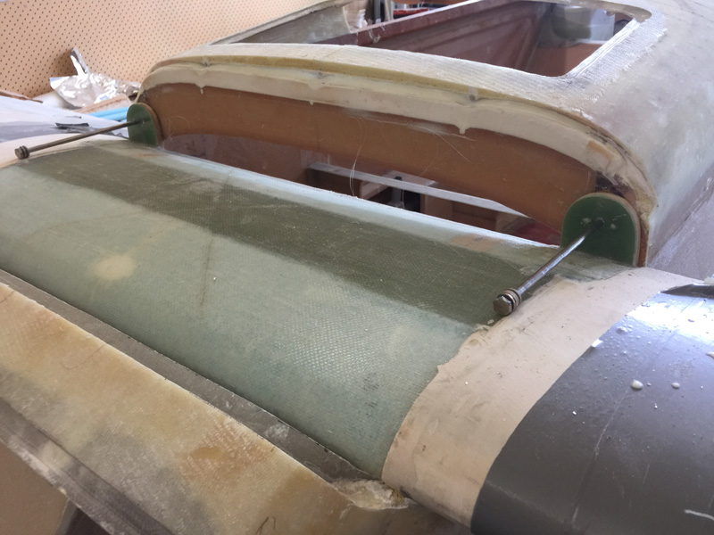
Here is our ‘before’ situation… nut plate at the canard and bolts needed to go from the panel area. Its just not going to work.
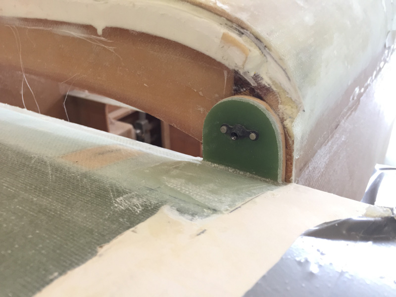
Here we are with the nutplates removed and our long AN3 bolts good to be inserted. These are so long the curve of the canard touches them!!
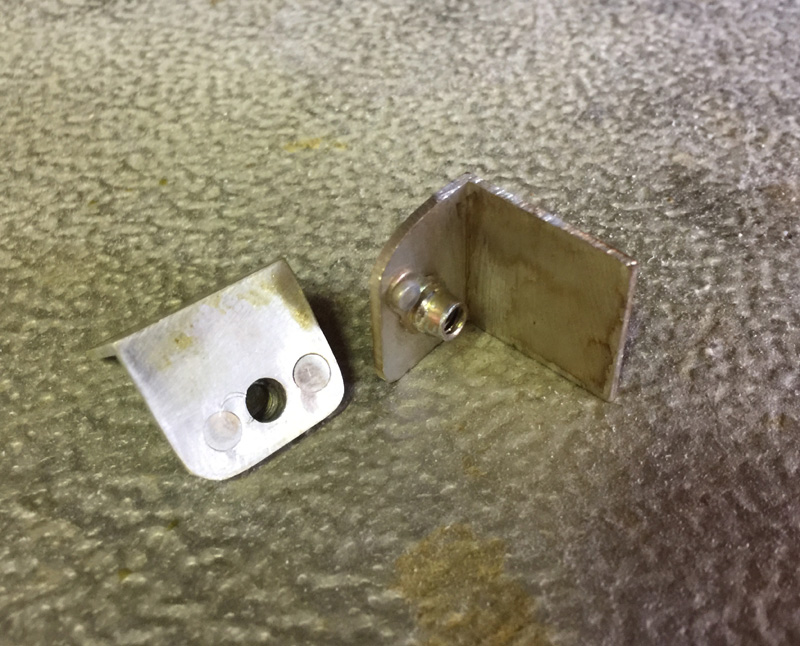
Here I’ve made a couple of nutplates on aluminium to size. I have an alodyne pen so while it’s not as pretty as a dip it get the items coated quickly and easily.
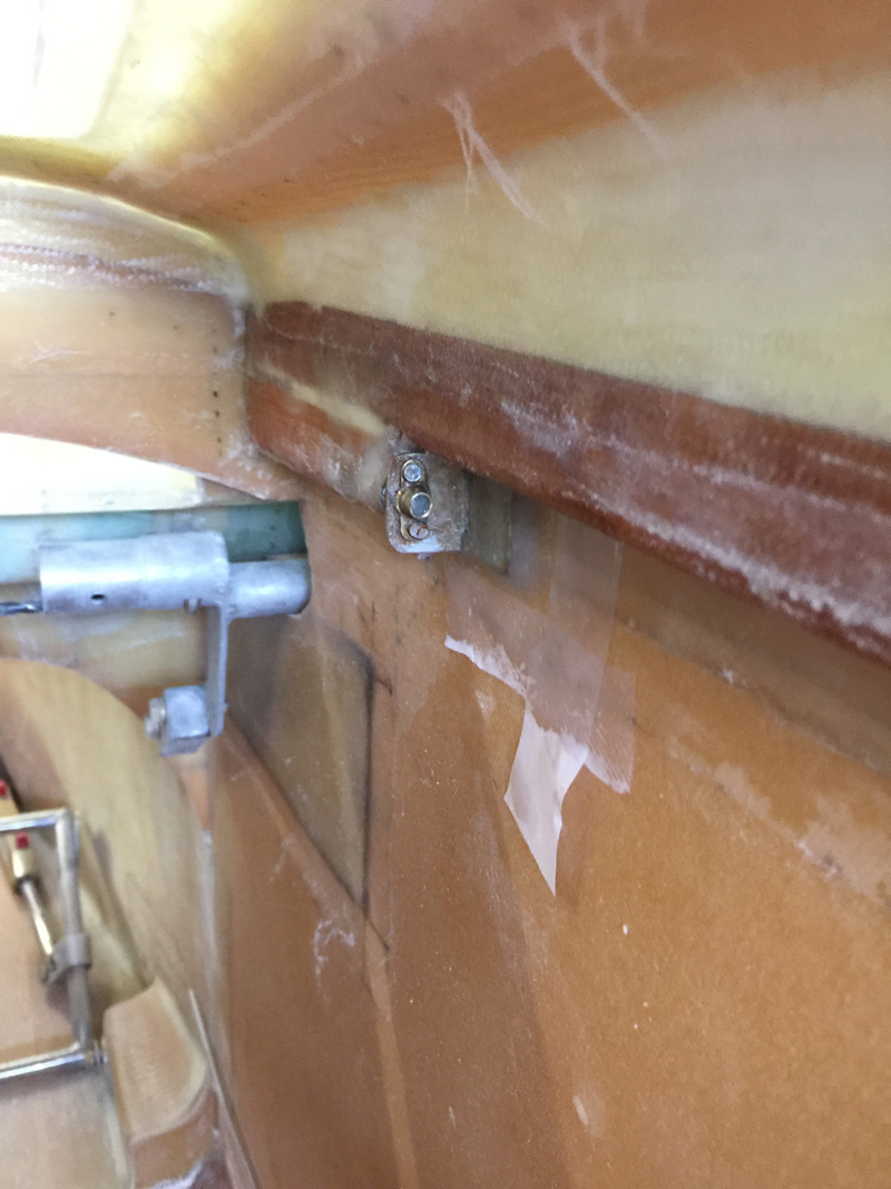
Here we are all done and floxed in place. I added on ply of BID to bind the bracket to the fuselage sides. Probably the flox would have been enough, but hey I like to be tidy and added a 1.5″ square with a little peel ply at the edges. I did go to the trouble of having the canard installed for this so I’m pretty confident it is all in line.


1 Comment. Leave new
Very nice work as usual…. glass layups look phenomenal. Maybe you’d like to spend a few weeks in freezing cold Virginia to provide me with some remedial glassing techniques! 😉