| Date: 02-05-2019 | |
| Number of Hours: 8 | |
| Manual Reference: no ref |
The cuffs are molded to the wing mainly upside down and the baggage pods get bonded to these later. My task is to make accurate marks on the floor and then transfer those to the wing so that my cuff layup is centered and in the correct position.
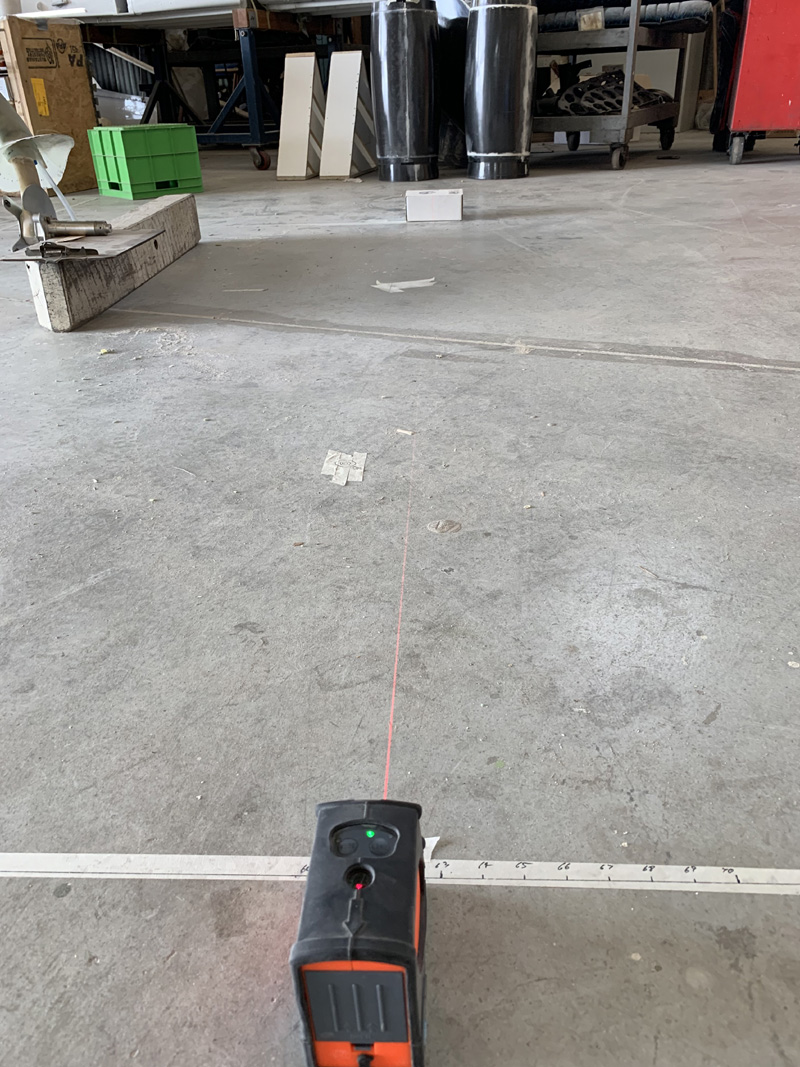
My little laser self levels with a built in gimbal if its within 5 degrees and tells you if its not. Perfect. Having used large carpenter squares off my center line I could easily measure out what became 61.5″ (BL61.5). This is about four inches from the wing to strake join on one side. Which means with allowing a maximum 7″ cuff width I’ll have a half inch buffer.
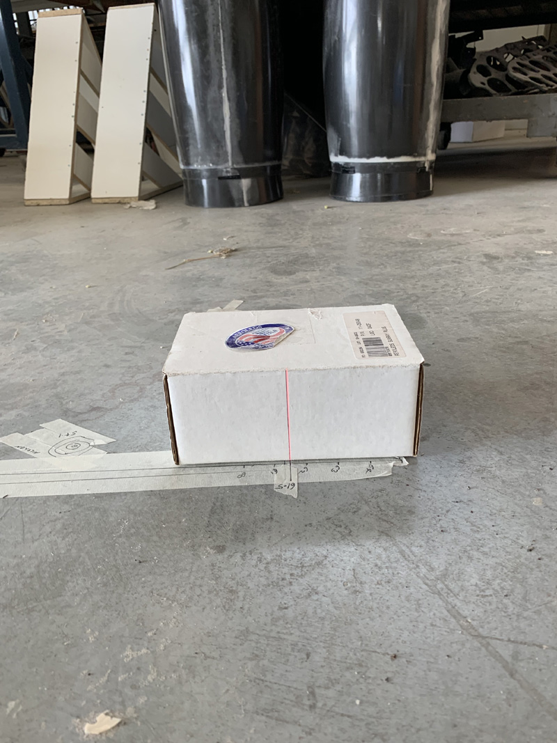
I measure out the 61.5″ from the centerline down at the engine end again using the square from the centerline to get a 90 degree line. I marked the line on tape and as you see above labeled the 61.5″. A thing with the laser is that after a few feet it’s hard to see the line on the floor anymore. In the above pic you can see that I have a box with a perpendicular line. Amazing, no line visible on the floor but there it is on the box. Woohoo. You can now easily see the laser mark and line up the two points to get a line parallel to the centerline under the plane but 61.5″ out.
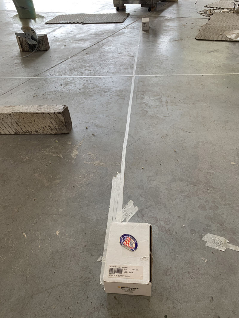
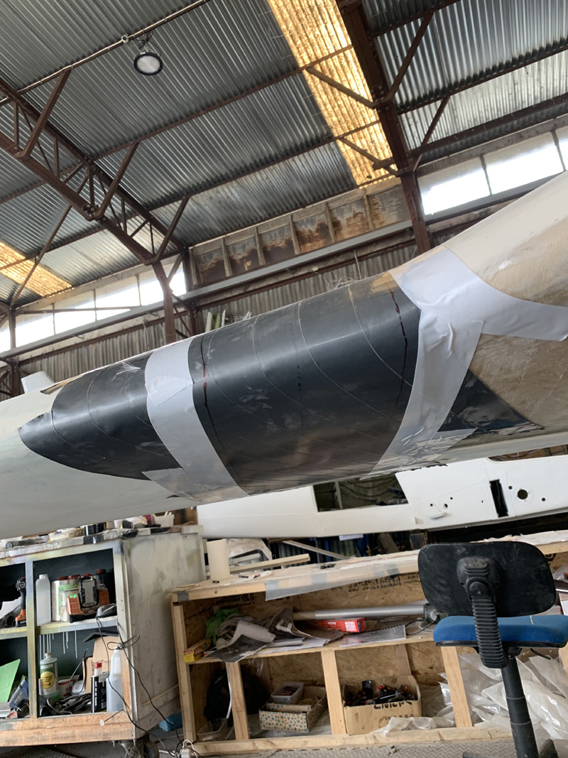
Here’s a wide view and I hope this explains what I’m doing a little better than the words. Yes the tape is a little crooked but the line on the tape is dead straight. I’m just using cheap masking tape on the floor to draw on rather than something more permanent.
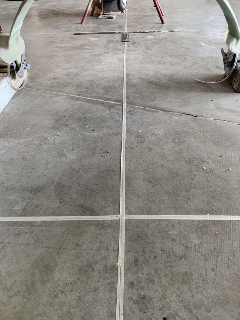
In this pic you can see the two big squares I’m using. I put them back to back exactly on the centerline then it’s easy to just draw the 90 degree line. Make sense? If not, drop me a note. Frankly I have trouble understanding this stuff but when I tell people they get it right away. Either I am fantastic at explaining it or pretty dumb in having trouble with something that is obvious to others. No need to tell me which.
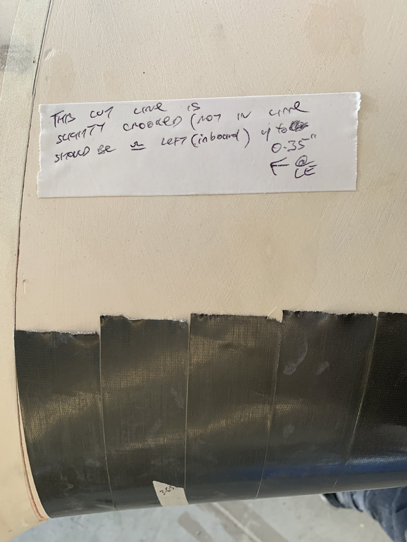
OK I finally found my missing .3 to .4 of an inch discrepancy that seems to be all over this when I got the serious measuring happening. All it is, is a slightly crooked line in that stake to wing join. I am really within about .10 to .15 of an inch from perfect in reality …and that amount would be ‘in the noise’ as we say.
This means that my decision is to have the baggage pods exactly the same distance from the centerline despite it being slightly closer to the crooked line on one side. That slight crookedness is not really apparent until you measure. Its looks pretty straight really until I point it out and even then…. Well trust me, the plane is nearly perfect hahaha. My lines here and there, not so much.
The really magic thing about the laser is that while I had it lined up on the floor and, as I showed, it magically climbed up my box at the same time. Well it also shined perfectly on the compound curve of my wing edge, right at BL61.5 Pity it doesn’t show in the photo eh?
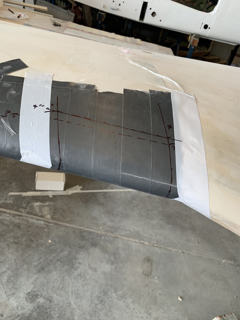
In the above pic you can see a dotted line in the middle. I just put marks where the laser was on the top and bottom of the wing. Then I marked out a line 3.5″ each side. Of course I also used the laser to help me position that cloth tape on the wing so I could draw on it later. The tape should be around the thickness of primer and topcoat paint as well as a release medium for the cuff.
The white tape on the sides is a gross outline so that when the wet and sticky cuff is going on I will have something very easy to see as outside guidelines. If I get the glass within those white tapes it should work out.
The pods came with pre-cut glass as you see above. No way am I going to get 7″ width out of these. They are really cut tightly. Long-EZ pods, the smaller ones have a 6″ width cuff. Mine might be 6.5″ or so. We shall see.
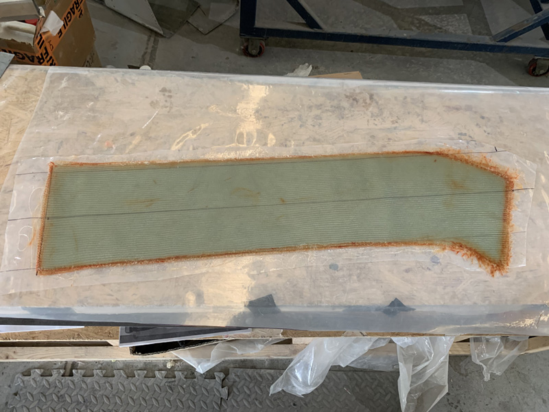
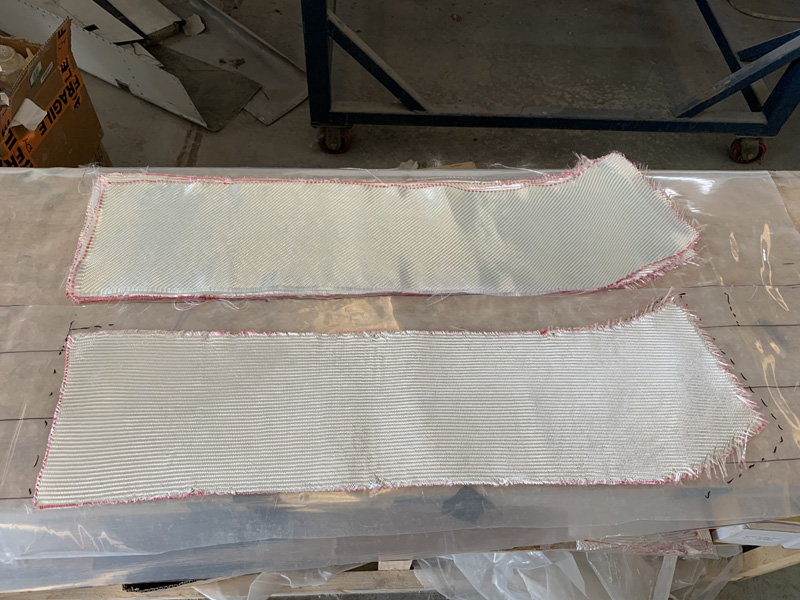
This is the left side cuff glass with all seven plies wetted out. Its about 32″ in length and I sure hope its enough. You can see the 7″ width lines top and bottm so I am really right on them.
I’ve wetted it out on plastic with a centerline and the 3.5″ guidelines. The sharpie pen marks are on the underside so the ink doesn’t bleed into the wet glass. You might note that I have trimmed the plastic to just above and below the glass and only a little excess at the top and bottom. I have differed from the instructions here.
I prepped the tape on the wing with pure epoxy using a folded paper towel as an applicator. This and the seven plies took two lots of 120 grams of mixed epoxy with not much over.
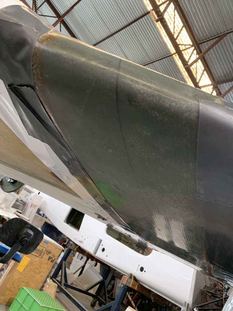
Again unlike the ‘instructions’ I only needed one assistant and no practice was required. I had the other person hold the longer, under wing section, at the end with two hands. I lined up the front section of the layup just over the 3.5″ mark and under the 4″ mark I’d made on the top of the wing. (You can see these marks several pics back) When I was ready I set it down and ensured my assistant had the rest of the layup in line with my center marks on the wing and plastic and about two inches below it. I then pushed the layup onto the wing front to back.
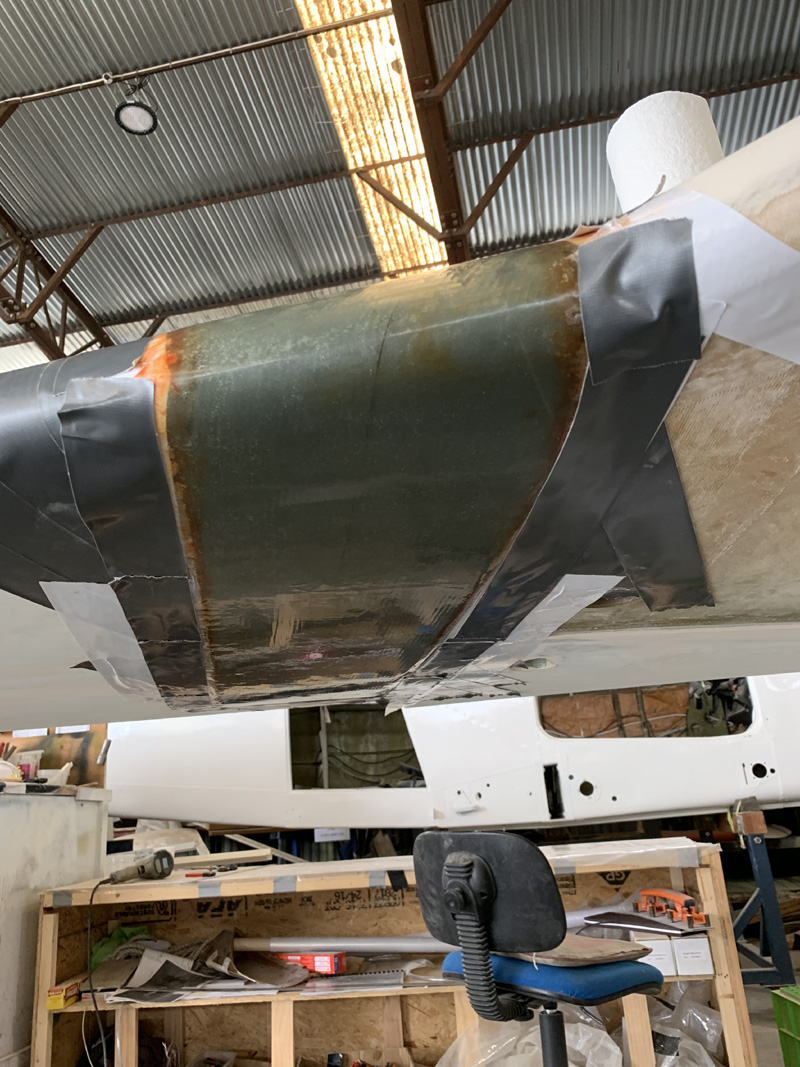
It immediately stayed put with no problems at all despite being mainly upside down. I eased any air out the sides and ends. Then I used a squeegee to really get it laid down nicely. When I was 100% happy I added tape to the ends and to the plastic sides. That layup was not going anywhere. Both sides are now done. Well at least the cuffs are on the wings.
On to the next step tomorrow.