| Date: 12-14-2011 | |
| Number of Hours: 50 | |
| Manual Reference: no ref |
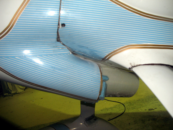
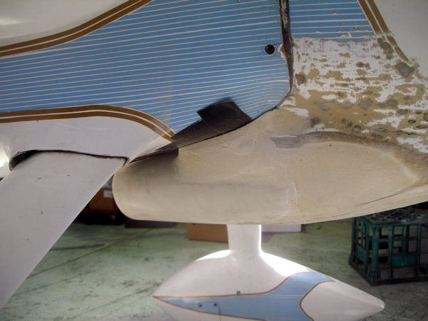
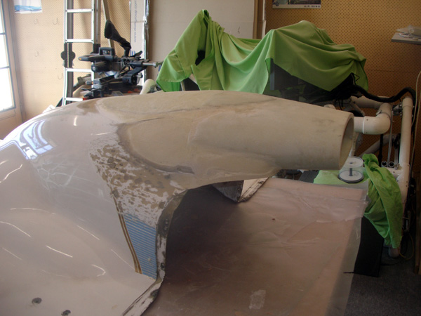
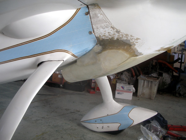
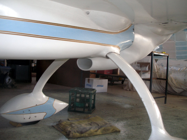
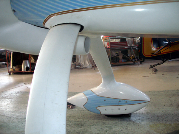
My Long-EZ overheated and the reason was that it was not getting enough cooling air to the cylinders. When I bought the plane I was told that the one CHT temperature sensor was on the hottest cylinder after careful testing by the builder. I always had good temps yet the plane before I got it kept having heat related issues in the cylinders which I could see in the engine log book. In that tradition I had my own problems too.
I finally got to the bottom of these recurring problems. The heat sensor was on cylinder #1. This is almost always the coolest on these pusher planes. The hot one is almost always #4 and thats where the most trouble was. Eventually I put in a JPI engine monitor and made a new air scoop. The scoop was a huge job. In retrospect I should have put in the new monitor and then rebuilt the lips of the scoop and see what that did first.
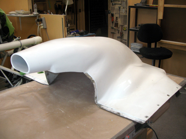
That’s with the knowledge I have now. Then I just went whole hog! Here are some notes I took at the time on building this Duct. I’m calling it a change from the plans P51 style to an F16 style.
I got a lot of advice and help from Terry Schubert and Rim Riggs. There is also a good article in the CSA Issue 85 page 8 by Kurt Wegge who replaced his original scoop. My thanks to these people for there generous gift of time and knowledge.
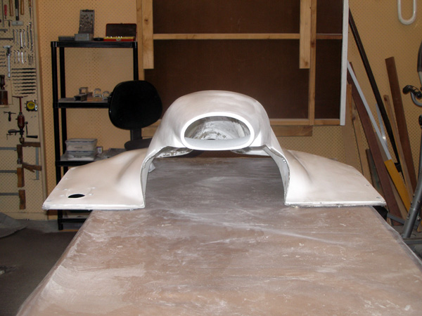
BUILDING an F-16 DUCT
Scoop or Duct has 11 degrees included sloping sides 5.5 degrees per side.
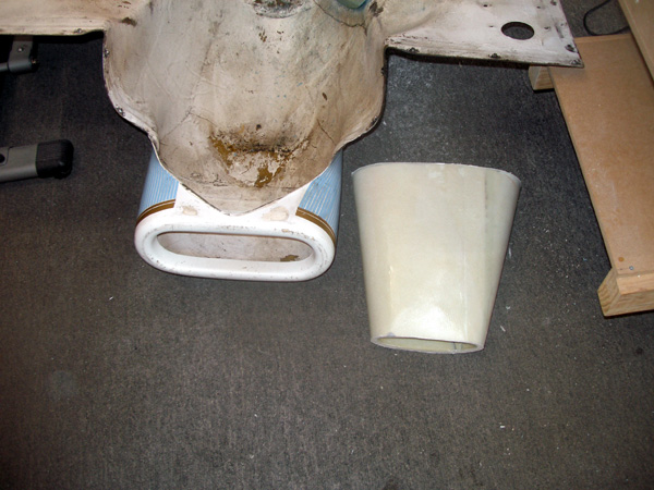
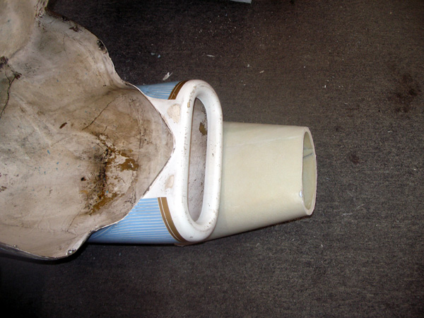
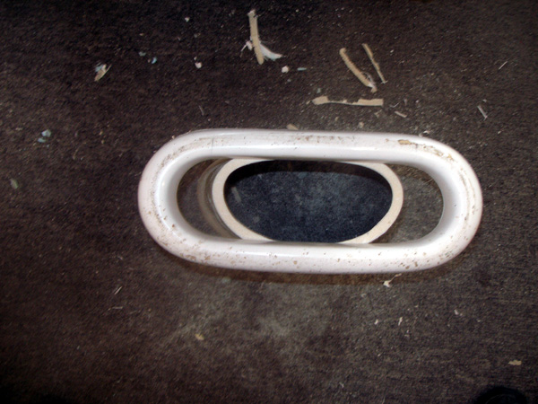
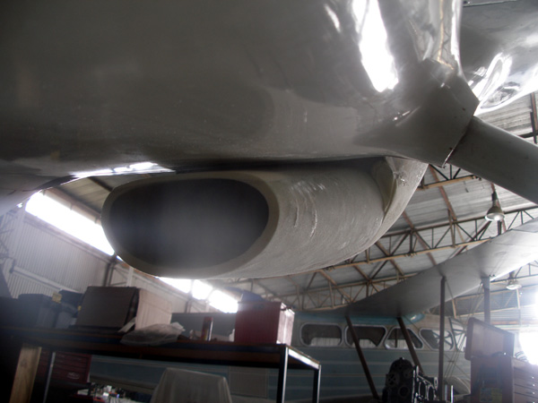
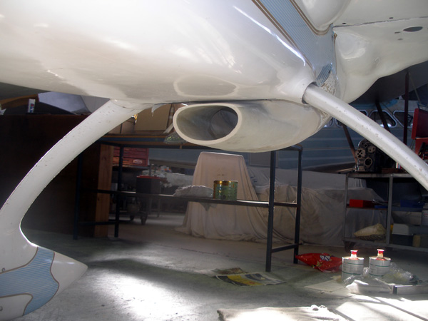
I first got a profile of an F16 duct from Russian website (not sure how important the opening shape is however I needed to get my hand in to to get to the gascolator for a daily fuel drain.
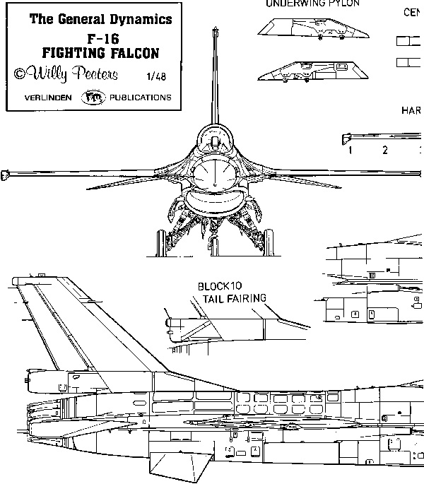
Above is the pic I found of a scoop and below after playing in Photoshop. Not very scientific I know.
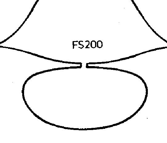
- Draw out on to graph paper and count the squares to work out opening size.
Use Photoshop to expand printed image until the scoop is the desired opening - Old plans P-51 was 35sq”Desired was 16 to 17”. I choose 19.1sq” in the end for a bit of safety margin. A smaller duct can be made at another time if necessary.
- We need to find the opening size of the expanded end and what distance it is on a 5.5degree slope. We also need to have the opening expand by at least twice. Three times is better. Then we have our expanded high pressure air.
- Draw out a straight line on paper. Then we need a triangle with 5.5degrees at the pointy end and a right angle at the other end. Use sin(5.5) to work out our dimensions.
Sin X length (l) = height (ht) ht = radius / sin(5.5)
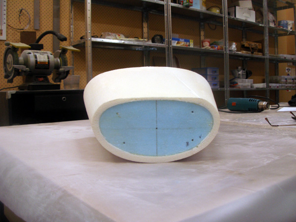
intake 3.4” at the highest point of the scoop shape (1.7” radius) = 19.28 sq”
firewall 5.7” (2.85” radius) = 54 sq” This is X 2.8 expansion
length = ht / sin(5.5) - Draw out the triangle on paper using the length as the vertical upright and once two lengths are known at a given distance apart then projections can be made in-between for a shorter or longer duct.
Once the diameter of the larger opening is worked out. Use Photoshop to expand a pic of the duct until it has the right diameter on a print out.
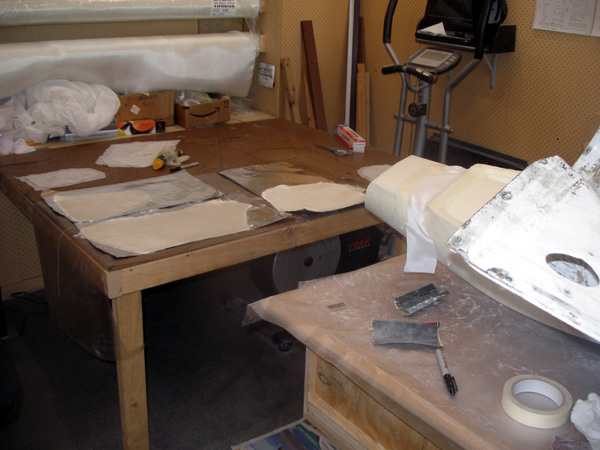
Confirm area by printing on graph paper and counting the squares (partial square count as half) - Make two templates using plywood or Masonite or similar. Strong, but not too thick.
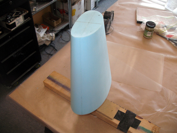
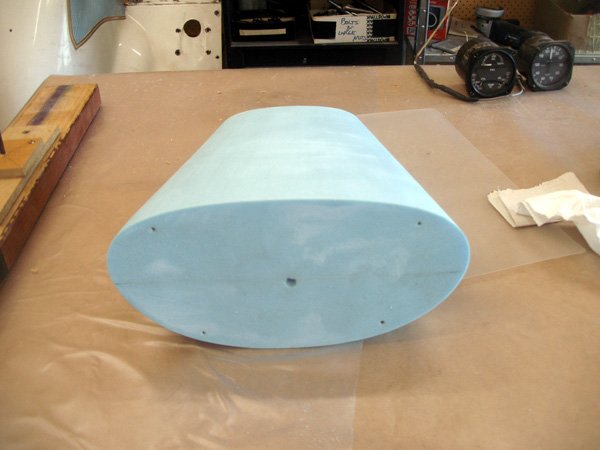
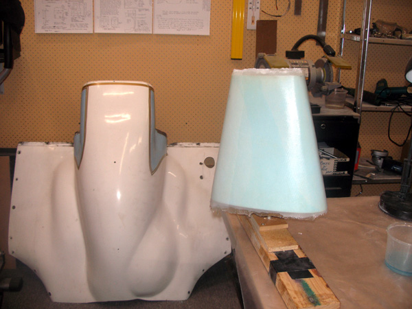
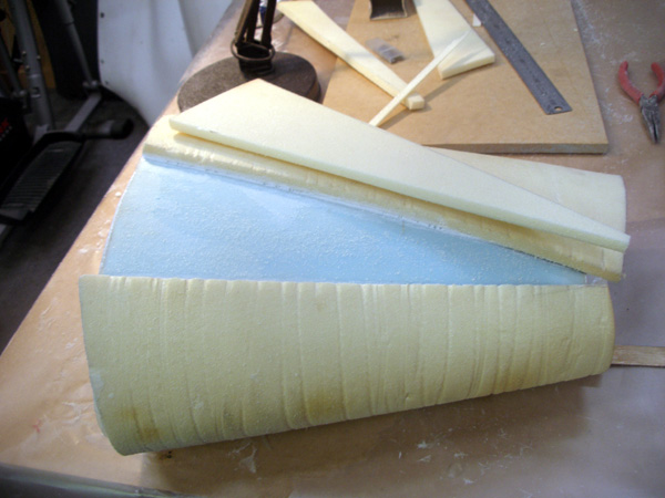
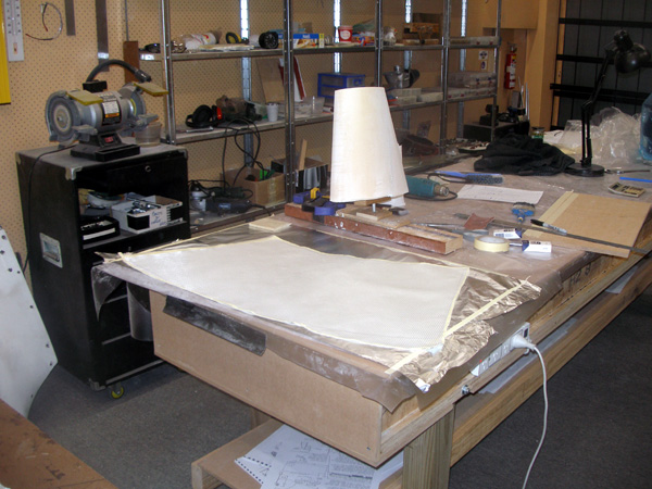
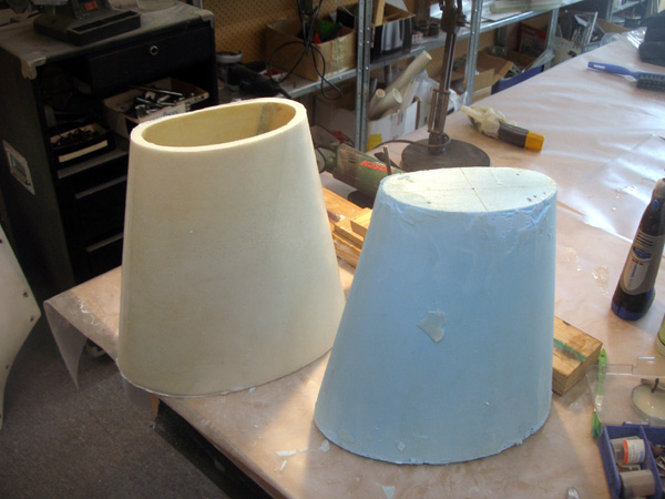
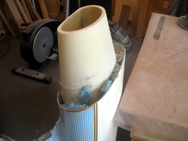
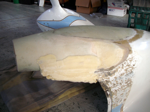
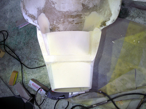
They need to be exactly centered on a block of blue foam and nice and straight the exact required distance apart (length of the foam block adjusted to suit) - Then cut away the foam and use a straight edge between the templates to form a perfect inner plug for the inside of our duct. This is the bit we want smooth and correct. The outside dimensions need only be for conforming with minimum drag to the airframe and for having a straight duct.
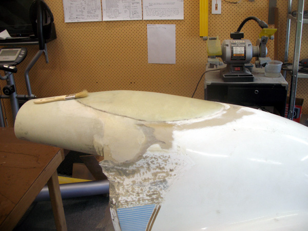
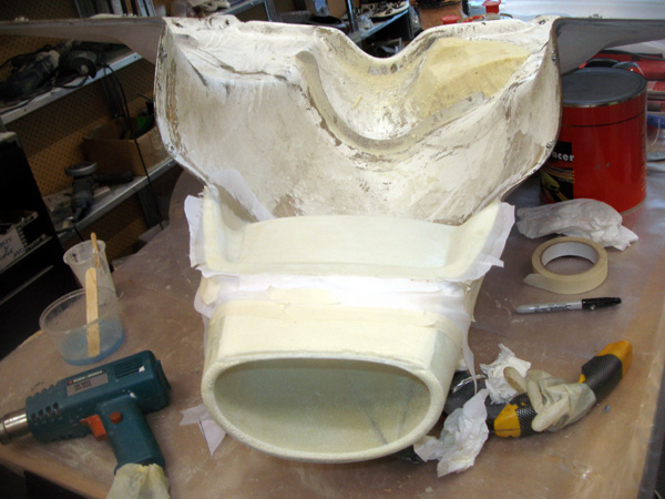
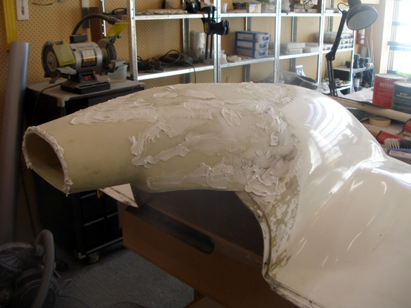
- 10 mm divinycell thermo formed and microed to the outside works well.
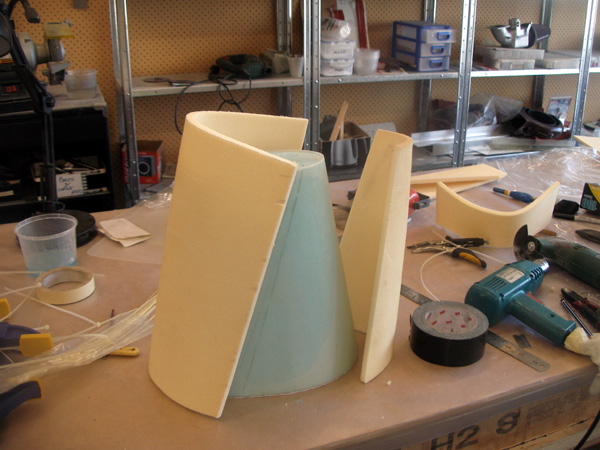
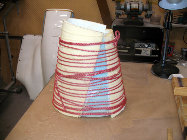
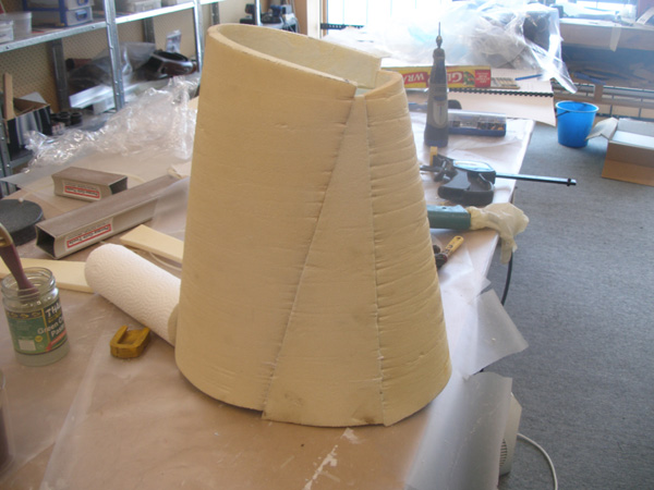
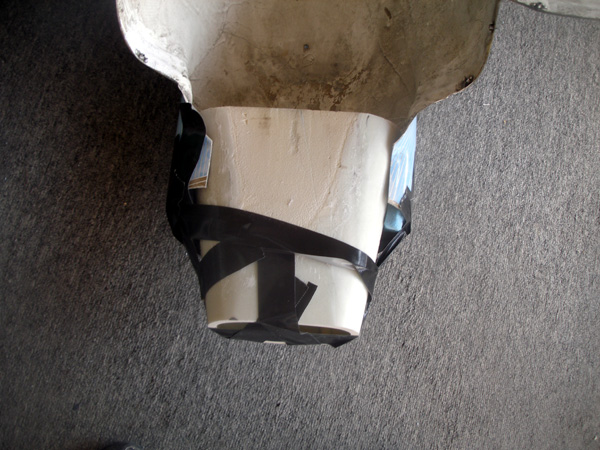
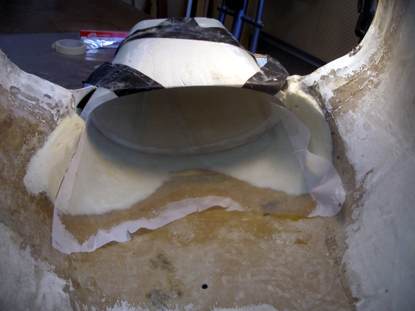
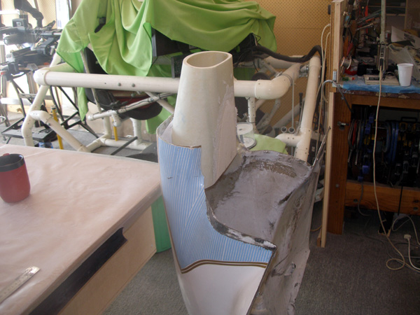
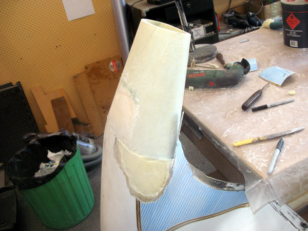
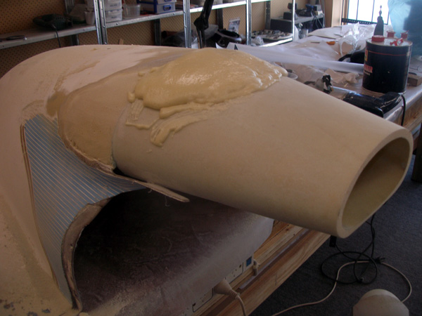
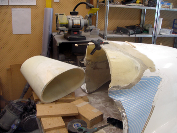
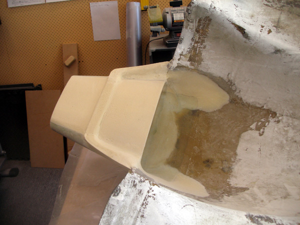
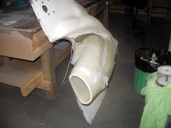
Place the plug on a holder so that two layers of bid can be layed up on the outside of the solid plug. Use plenty of wax and a release like hairspray or PVA (if you have a spray). Peel ply all of it for a smooth interior of the duct. - Leave it on the plug while you form the outside foam (must be fuel resistant) urethane of some type. You could use tape or rope to form the foam around the laid up plug, it takes a bit of heat to round the divinycell. It can be done in strips or maybe 4 pieces. Anyway you like as its not critical, its to make a cored part that is light and strong. You already have the correct inner shape.
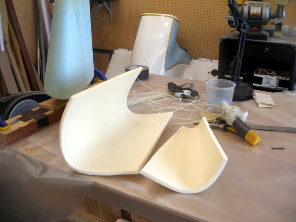
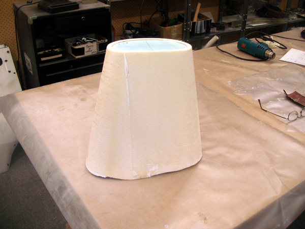
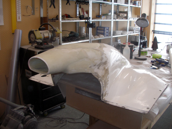
- After the foam is microed on. Clean it up and lay up two plies of bid (45 degree of course) over the out side. Once cured you can gently remove the inner plug. It should come out in one piece and a very thin knife slid down the sides upper and lower should do the trick.
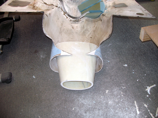
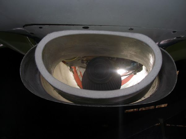
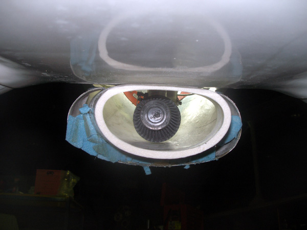
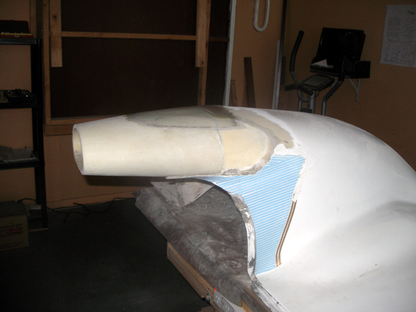
Here are 47 pictures of what I did. If you are contemplating this I am positive there are better and easier ways!

1 Comment. Leave new
Hi Dave,
Your thorough workmanship is a joy to see!
If you ever decide to further reduce the inlet area you can easily just make the lip a touch thicker to use up some of the opening.
The flow divider between the fuselage bottom and the top side of the inlet might be made pointed instead of flat to reduce the drag through that slot. You’ll probably not get more than 100 kts out of that but on your LONG trip, it might make a noticeable difference.
Thanks for sharing your wonderful workmanship.