• Home
  • Flying
    • First Flight
  • Build by Chapter
    • Ch 3 Education
    • Ch 4 Fuselage Bulkheads
    • Ch 5 Fuselage Sides
    • Ch 6 Fuselage Assembly
    • Ch 7 Fuselage Exterior
    • Ch 8 Roll Over/Seat Belts
    • Ch 9 Main Gear/Landing Brake
    • Ch 10 Canard
    • Ch 11 Elevators
    • Ch 12 Canard Installation
    • Ch 13 Nose and Nose Gear
    • Ch 14 CenterSection Spar
    • Ch 15 Firewall and Accessories
    • Ch 16 Control System
    • Ch 17 Roll/Pitch Trim System
    • Ch 18 Canopy
    • Ch 19 Wings, Alierons
    • Ch 20 Winglets/Rudders
    • Ch 21 Strakes – Fuel/Baggage
    • Ch 22 Electrical System
    • Ch 23 Engine Installation
    • Ch 24 Covers/Consoles
    • Ch 25 Finishing
    • Ch 26 Upholstry
  • Build Mods
    • Liquid Cooling, Numbers, Weights and Flow
    • Cooling
      • Solving Ground Cooling 1
      • Solving Ground Cooling 2
      • Solving Ground Cooling 3
      • Solving Ground Cooling 4
      • Solving Ground Cooling 5
      • Solving Ground Cooling 6
      • Solving Ground Cooling7 – Test Data
      • Solving Ground Cooling 8 – Flap Building
      • Solving Ground Cooling 9 – Hinges
      • Solving Ground Cooling 10 – Lower Flaps
      • Solving Ground Cooling 11 – Upper Flaps
      • Solving Ground Cooling 12 – Completed
      • Cooling the Beast 1
      • Cooling the Beast 2 – Lower Cowl Expansion
      • Cooling the Beast 3 – KW Oil Cooler Diffuser
    • EVS (Enhanced Vision System)
    • Cowl Keeper
    • Rudder Gust Locks
    • Wing Fences
    • Post Cure
    • Hinge Upgrade
    • RAM Air & Hellhole Cover
    • Main Gear Beef Up
    • Pilot Side Windows
    • Baggage Pods
    • Winglet Intersection Fairings
    • Titanium Rollover
    • Nose Gear Doors
    • Wheel Pants/Gear Leg Fairing
    • Cabin heating System
    • Fuel System
    • Roll and Pitch Trim
    • Oxygen System
    • The Ferry Tank
    • Cruise Angle Indicator
    • Fire Extinguisher Install
  • Round the World
    • RTW Route East #12 rev1
    • Survival Equipment
    • Training Flights
  • Other Stuff
    • Blog
    • Around the World: RAAUS Sport Pilot Issue 110
    • Taxi Tests
    • Summary Feb ’24 from an SAAA Meeting
    • AOPA Pilot 27th Sept 2019
    • Build Tests
    • Flying Stories
      • A Long Easy Dream ’06
      • Townsville ’07
      • Cairns ’08
      • Albany ’08
      • East Coast ’08
      • Brisbane ’09
      • Cairns ’10
      • Perth ’10
    • Non Build Mods
      • F16 Scoop for JZE
      • Ram Air Box for JZE
      • Strange Tips
    • Milestones
    • Links
  • Contact

Blog

Home
Build Mods
Pitch Trim Servo Install 1

Pitch Trim Servo Install 1

7 years ago
Dave Berenholtz
Build Mods, Ch 17 Roll/Pitch Trim System, Roll and Pitch Trim
Date:  09-08-2018
Number of Hours:  10
Manual Reference:  no ref

As VH-XEZ will be a well equipped IFR aircraft, I’ll be having an auto pilot. I’m using mainly Garmin instruments and this means a GSA 28 (Autopilot Servo) for pitch and another will be installed later for roll. I’ve been in touch with the very helpful guys at Garmin, some of whom have Long-EZ. They tell me the place to install these servos is on the canard.

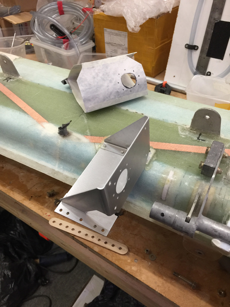
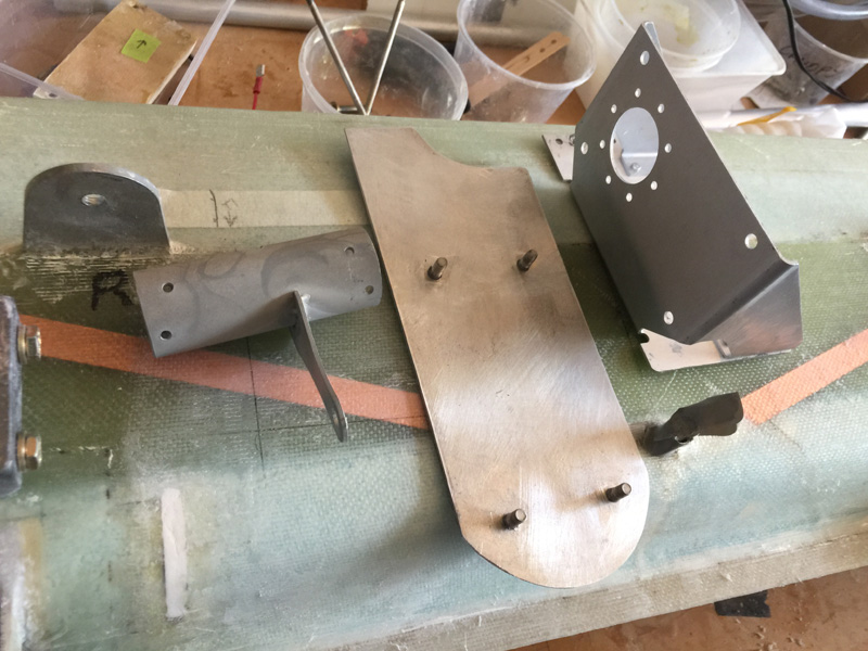
I read the install manual a few times and got familiar with things. I’ve already bought the servos and a bracket kit. It looked like it goes somewhere in the above area. I made a cardboard cutout after a while as I just couldn’t see how to get the the canard on and off once I install the servo! It was snagging on all the nice air sealing work I’d done. The offset torque tube I’m using also made things harder because the counterweight also seems to snag.

As I’m saying more and more, “No modification goes un-punished”.

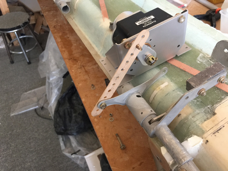
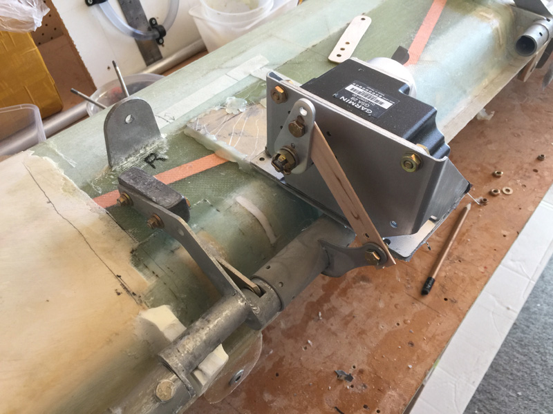
I had purchase the trim bracket with this servo in mind. I guess this was a rare planning win. You can see above a beginning of how it might fit and operate. I’m just using a drilled mixing stick to get a feel for placement and the ‘throw’ of the servo and elevator together.

I have concerns about how far from the canard edge this thing needs to go so I can still get the canard off. With hot gluing things in place I tried several positions.

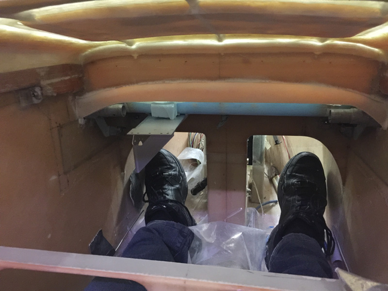
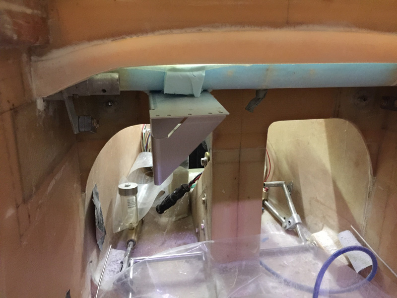
This spot seemed pretty good. My feet work out OK.

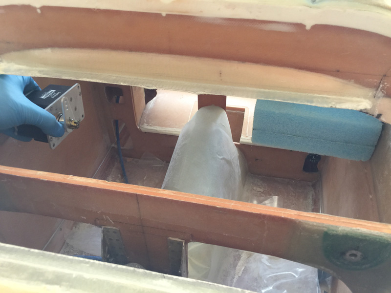
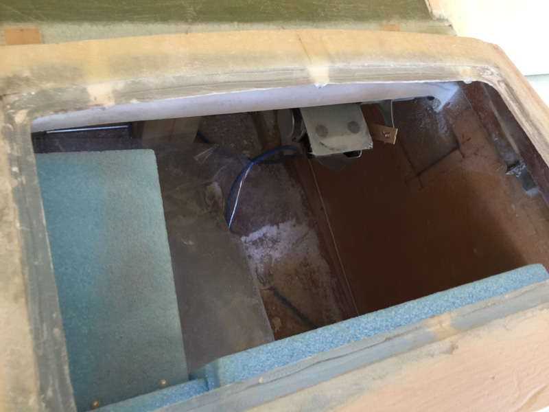
Here’s the reverse angle. That blue block is the radio stuff going full length forward to F28 (I think it is). Fellow LE builder and ace planner, Wade Parton, commented that I might run into trouble with my Garmin main stack of toys on that side being too deep. He was right, thanks Wade! Maybe I would have spotted it in time or maybe I’d be in a world of hurt in a few months doing the avionics install. Now we will never know.

Here’s a mock up on the opposite side All I have in from here is the G5 which is not very deep. There is still plenty of room for the pitch arm from the stick that goes on that right side. This is another mock up with more hot glue.

Each time I have to lift the canard off and manipulate it in my small room. Its been a couple of dozen so far. I may need a physio, things are starting to hurt.

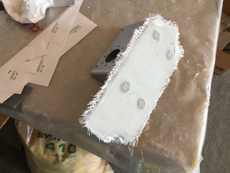
Now I’m happy with placement I hunted everywhere for a bit of aluminium for the base. I’ve added click bonds and then glassed over the back with a ply of BID.

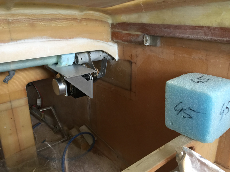
More mock up tests. You can see I’ve modified the pitch trim arm too. The canard again went on and off several times.

Here it is in place as I’ve been trimming my air tight fairings around the canard a little too. The foam block on the left is where the GTN750 goes so being on the opposite side is lots of room. The downside is that the overhang of the servo relative to the canard is quite extreme. I’m going to have to make the attachment very solid.

Here’s my base place with the clickbonds ready for fitting after prep work.. The canard is removable, but its a little tricky. I may do a write up in the flight manual on the ‘how’.

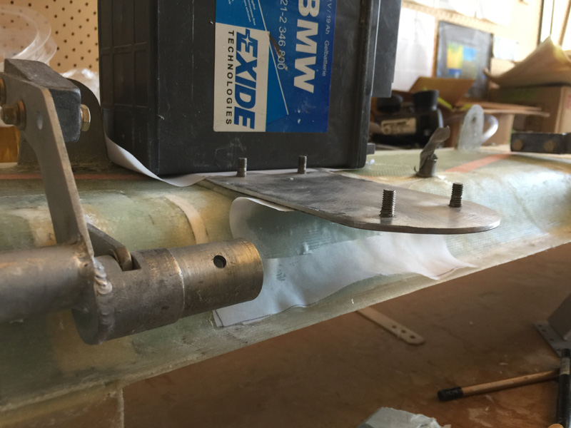
I’m using West with flox here and a bit of weight while it cures. That metal MUST clear the torque tube of course. I like West and metal as its just a little less brittle than my usual epoxy. Good for this type of job, and it has a fast hardener.

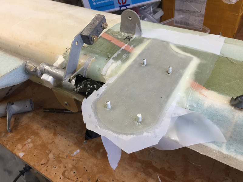
After the Canard to metal cured, I’ve done two ply of BID overlapping onto the canard and one of UND on top. I’ve also added some micro underneath. I’m going to make a support there and shape it so its clear of the torque tube but still adds a little extra strength to that ‘overhang’ with the servo on it.

Previous Post
Oxygen Install 4
Next Post
Winglet Intersection Fairings 1

1 Comment. Leave new

  • Wade Parton
    10/09/2018 2:35 am

    Glad to help! Looks great! 🙂

    Reply

Leave a Reply Cancel reply

Your email address will not be published. Required fields are marked *

Fill out this field
Fill out this field
Please enter a valid email address.

CategoryLogsHours
All157617079
Uncategorized135
Ch 3 Education220
Ch 4 Fuselage Bulkheads25231
Ch 5 Fuselage Sides32283
Ch 6 Fuselage Assembly30270
Ch 7 Fuselage Exterior14140
Ch 8 Roll Over/Seat Belts990
Ch 9 Main Gear/Landing Brake71642
Ch 10 Canard28287
Ch 11 Elevators36298
Ch 12 Canard Installation12102
Ch 13 Nose and Nose Gear1291097
Ch 14 CenterSection Spar57525
Ch 15 Firewall and Accessories448
Ch 16 Control System27237
Ch 17 Roll/Pitch Trim System654
Ch 18 Canopy70502
Ch 19 Wings, Alierons1271090
Ch 20 Winglets/Rudders71528
Ch 21 Strakes - Fuel/Baggage65437
Ch 22 Electrical System591031
Ch 23 Engine Installation961152
Ch 24 Covers/Fairings/Consoles25202
Ch 25 Finishing561084
Ch 26 Upholstry340
Fuel System46310
Rollover1050
Cabin heating System60331
The Ferry Tank335
Blog2694182
Build Mods2252513
Nose Gear Doors856
Wheel Pants/Gear Leg Fairing40473
Oxygen System762
Roll and Pitch Trim964
Winglet Intersection Fairings445
Baggage Pods11104
Pilot Side Windows437
RAM Air & Hellhole Cover15177
Main Gear Beef Up322
Post Cure124
Fire Extinguisher16
Wing Fences13
EVS (Enhanced Visual System)130
Hinge Upgrade115
Cowl Keeper110
Rudder Gust Locks19
Cooling20607
Taxi Tests42
Flying10

Complete the Test Flight Program

2025/6/30 10:26:01

Round Australia in Four Flights

2026/4/1 10:26:01

Round the World Departure

2026/8/22 10:26:01

Rough River Flyin, Sept 23, 2026

2026/9/23 10:26:01

© Copyright 2025 Dave Berenholtz