| Date: 01-16-2017 | |
| Number of Hours: 10 | |
| Manual Reference: 23-1, IIL-6 |
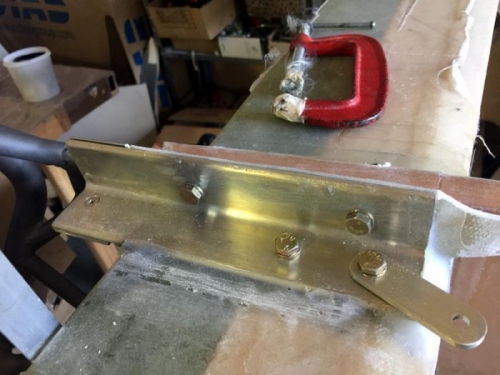
After the engine mounts were floxed in and cured I installed all the securing AN hardware. Mainly bolts and I went for wide area washers on the inside of the CS Spar. This is to spread the loads even though its not per plans and adds a little weight. It just seems to make sense to me.
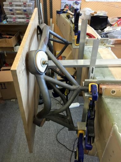
Pic 2 has the engine mount yet again in the correct place and its all looking good. From here I marked out where the bolt holes need to go in each mount ‘leg’ and so through the extrusions.
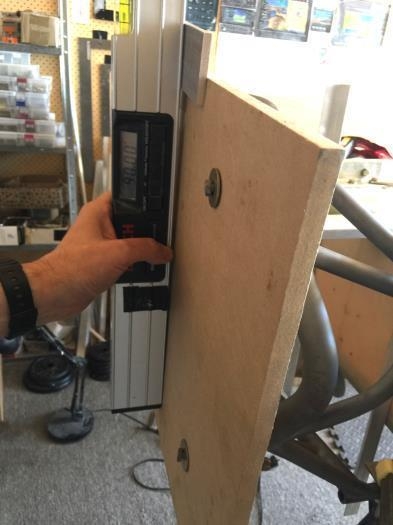
Pic 3 is the last check to ensure that with the back of the spar at 90 degrees, if I add .25″ to the top of the mount, as you see in the pic, I get back to zero again. So the mount is angled up at the spinner end if you like.
The measurements are exactly per plans and that yields 1.1 degrees at the mount and I assume somehow that becomes 2 degrees nose up. This part is still a mystery but all my investigations tell me just use the measurements per page 15 of the engine installation manual from Mr Rutan and all will be well.
AN bolts installed
Final check
Angle check


