| Date: 10-28-2014 | |
| Number of Hours: 10 | |
| Manual Reference: 22-4 |
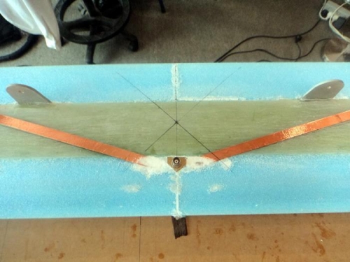
Few things have caused so much indecision lately. The Nav antenna is very simple. Its a dipole with ears 22.8″ long each side made from thin copper foil with a sticky backing. The ears need to have a 15 to 30 degree angle so there is no frequency hole. I measured a minimum of 15 degrees which allows the ears to just run short of the leading edge.
After a great deal of thought, many emails to other builders and reflection on my flying plane and a lot of reading I came up with a very lightweight and maintenance friendly solution.
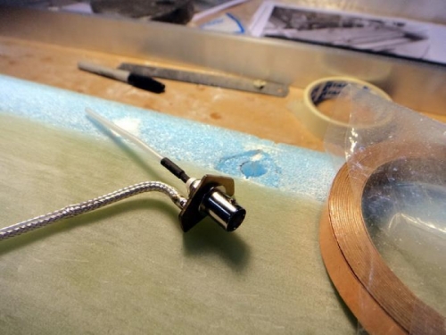
I made a small plate to hold an antenna fitting after deciding that I could put the toroid beads on a connecting lead. My decision is that they don’t have to be embedded in the canard. All of a sudden I get very short leads as in pic one stripped from a piece of RG400 cable. Next solder them in place after working out the angles and marking that on the foil. Simple and easy. Another bonus is that with the beads and heat shrink I can make the lead so it can not interfere with the moving elevator torque tube. Nice.
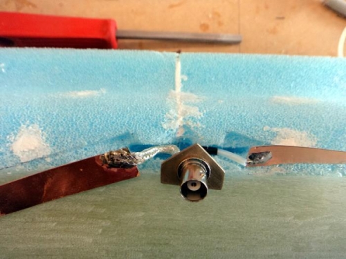
I routed a pocket into the canard and along with the alodyned plate made it all fit well and then potted the lot in stiff micro. The plate is to give extra strength given a lead will be going on here and then need removal with the canard. Its a LOT better than a dangling lead which was a pain in my flying Long-EZ. I did ensure that the solder lumps are below the level of the canard so the only protruding part will be the BNC panel socket fitting.
When the skin goes on there will be two plies of UNI in that area. Finally I’ll do a small BID patch over the top of that after the bottom skin layup given there is a gap in the BID middle ply at that point. Good result.
Antenna parts
Fitting the Nav antenna
Installed on the Canard bottom


