| Date: 01-20-2024 | |
| Number of Hours: 30 | |
| Manual Reference: 23 |
This post is a few words on what has been more than a full weeks (7 days) worth of work. I’ll just hint as some of the many things I’ve done although there is not a lot to see.
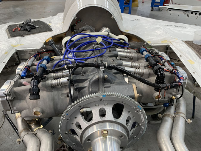
Not shown are a lot of wires under the plane. Pretty much all the EFII wiring is loosely laid out now. I have the spark plug leads connected to their blocks but I won’t terminate the ends until a lot of other things are done. The idea was to at least lay out wires and put them roughly where I think they will end up and connect it all at the firewall. I expect they will get moved as the coolant and oil pipes go in. At least I have an idea what I’m up against.
Oh and I connect the two MAP lines and spent a while running one into the rear cockpit to the fuel regulator. One of many little jobs I didn’t even photograph.
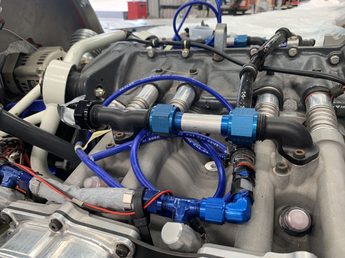
You might see above that the top coolant lines have been reversed as I worked out a run where these go under the engine and then join up at the firewall to go into the top of the two radiators. Once I did this the rear fuel line needed to move a bit. I had to buy more fittings and then move clamps and add rubber buffers. All good.
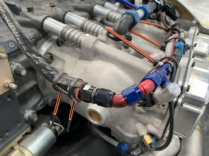
Then I got one of the radiators and found that the top outlets needed to go back to the other side again! What you see above is my amended pipe run that now needs to be changed again.
The other part of the equation was that I’ve also bought a -12 to -16 to the pump fitting as a tee rather than the Y I had planned. This is for exit from the lower radiator outlets. Trust me this will work. As ideas come, and I keep buying more fittings the pieces are starting to fall into place.
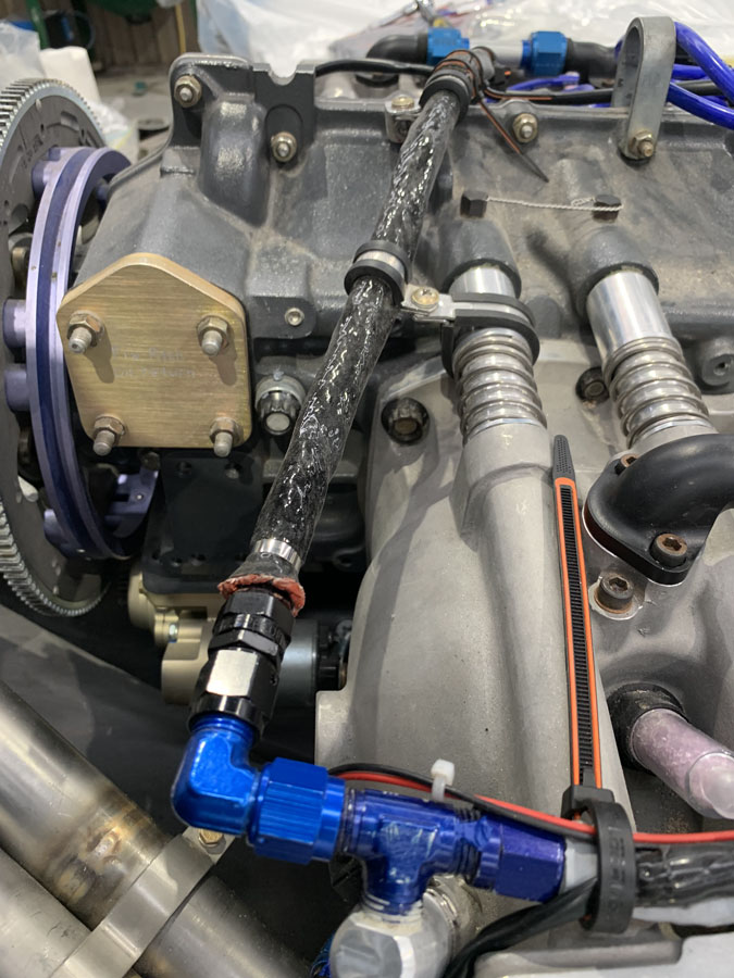
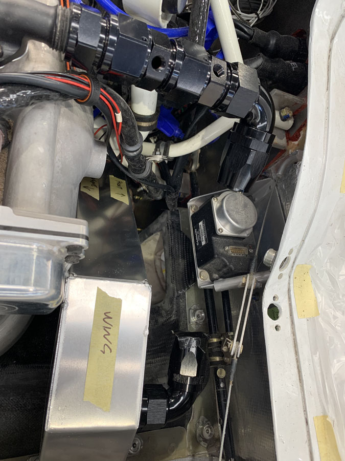
So here we are with the top pipe back to a right angle fitting and a much straighter run. I showed this small part of what I’m doing to say I have 4 or 5 similar things on the go. Back and forth ideas and trial fits.
Now this looks ‘right’. The fuel (black colored) pipe is well supported and has a couple of rubber buffers where it almost touches the top of the engine. Chafing is not an option.
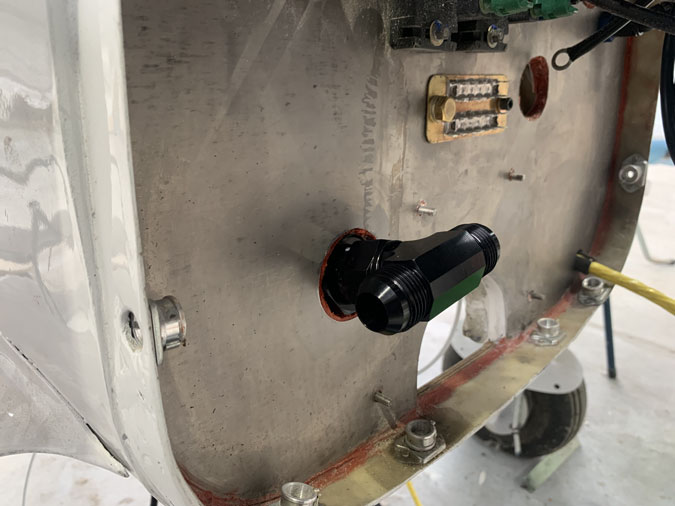
Here you see where the top engine coolant line are now going on a very direct short path to the top of the radiator/s. We have -16 fittings for this part. Now the two fittings with holes are 1/8 NTP. One will take a temperature sensor and the other will be a -6 hose to the expansion tank with the radiator cap.
I am thinking I might be able to tap a thread in one fitting and have two things coming off it. I may save the weight of one fitting which is nothing but good. However it lines up beautifully for the hose if I leave it as is. Like so many things I will play around for a while and the answer will come.
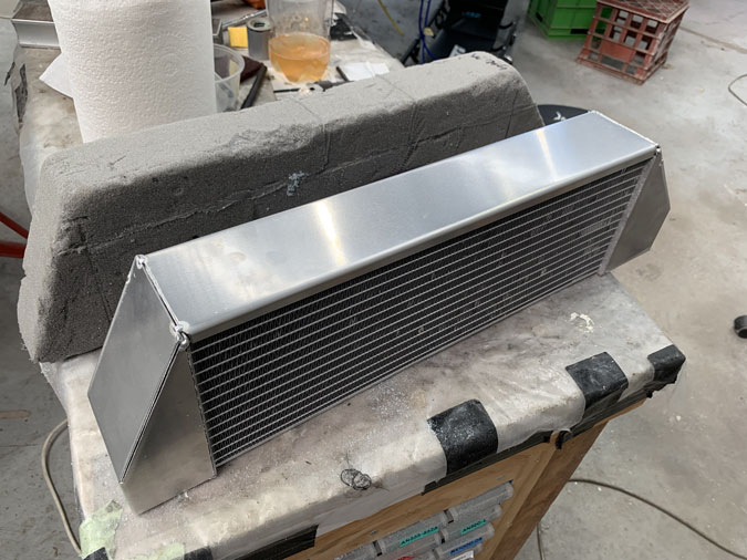
OK now for the big news. I have one of the radiators. This is how I’ve been able to advance a bit on the hose/pipe placements.
It is pretty much the same size as my now well worn dummy. The ends are just tacked together as we all know there will be changes. In fact I’m going back tomorrow with a short list of alterations.
Contrary to my drawings and explanations both in/out fittings were on the same side. However this mistake has really worked out perfectly and I need to let ‘Rod’ know that I want the remaining one done the same way. For once I was lucky. I am going to see if we can now get the tanks ends made smaller.
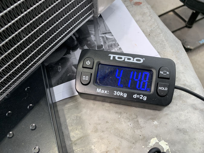
The weight of this unit is a hefty 4lbs 15ozs (14.8oz to be exact). It is however necessary and the thickness is required given such a marginal surface area. I spent a few hours playing with positions of course and thinking about how in the world am I going to mount these things! I have a couple of ideas. I need to mount this right side one before I can start the duct to the air inlet in the lower cowl. The placement is critical for a good fit. I didn’t know this was the first job until I had the radiator in my hands. This is how it works for me.

