| Date: 10-06-2022 | |
| Number of Hours: 17 | |
| Manual Reference: 13-10 |
Plumbing the pitot and Static System.
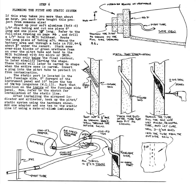
This is what we have in the plans, a very practical simple setup.
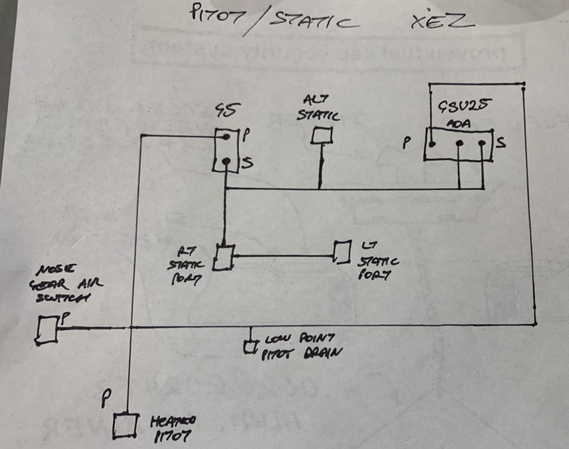
This is my mud map of a far more complex system, and what I need. It represents the whole of my build in a way. If I’d kept to the plans I would have finished years ago. That said, this plane has a different mission to the fun, lightweight, day VFR aircraft that Burt designed. A hard IFR, round the world platform with a range of around 2500nm and economy cruise of at least 3 nautical miles a minute is a different animal.
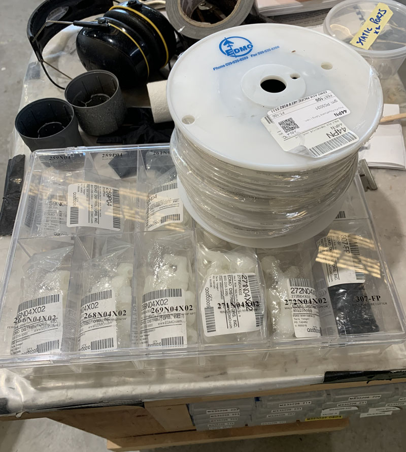
There are so many fittings that if I bought what I thought I needed then I would have been paying for extra postage and weeks of fiddling around. Working it out from a catalog was nearly impossible. I spent quite a bit extra and got an assortment that will last me the rest of my life and probably help out on some other peoples planes.
The next step was to see how I could get from my pitot and static fittings to the instruments.
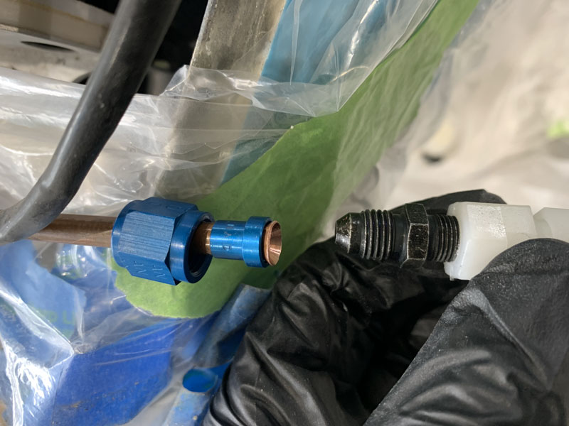
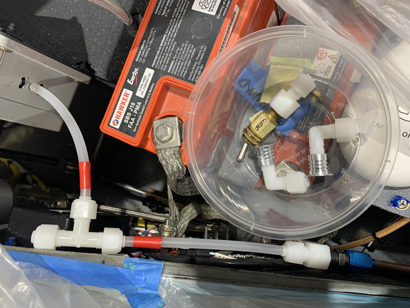
The heated pitot had a 0.25″ OD metal tube for connection. I flared it and added an AN fitting to mate with the hard plastic and second AN firewall joiner. This worked out pretty well in the end. Most of the plastics are 1/8″ NPT which took some finding out. These sizes are a black art as many are ‘almost’ the same, but not quite.
The static fittings and alternate static source switch also needed to come to the party.
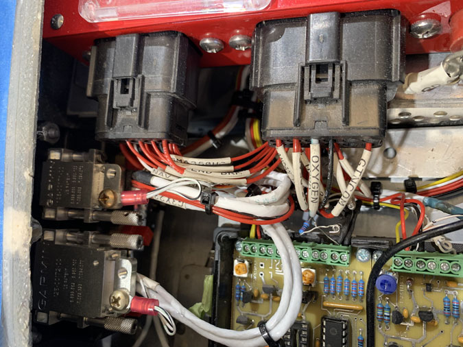
Where the connectors go on the left is where tubing now needs to live.
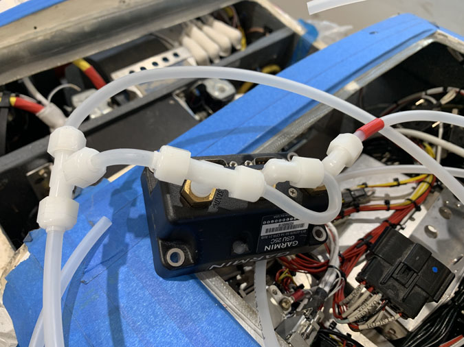
Here’s the first GSU25 connections. There were a few similar tries before I could make things fit. The center AoA has to connect to the static port even though angle of attack its not used.
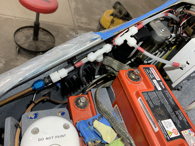
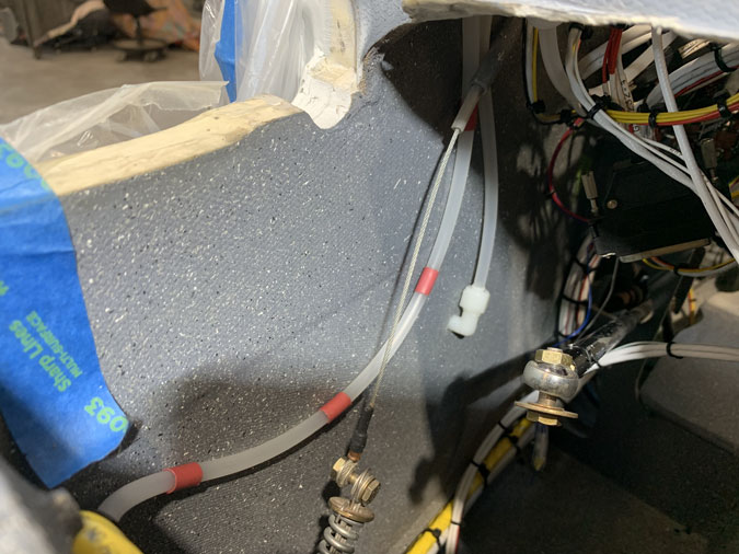
The Pitot became quite neat in the end. I used red heat shrink to indicate pitot lines. The static lines are just clear tube. At the second join is a drain tube to the bottom of the nose. The side tube is a static source for an airspeed switch for the nose gear emergency extend.
The static ports on both sides needed careful placement around the rudder cables. I also need access as these might require some adjustment during test flying.
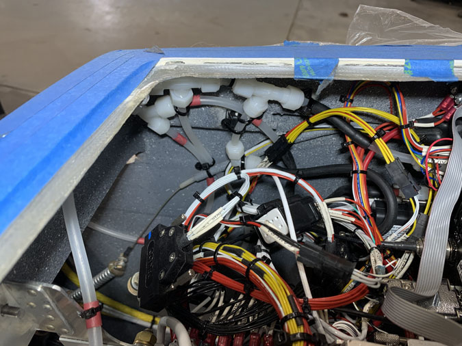
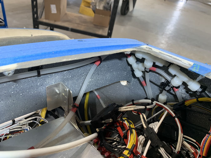
The many joins are all necessary and somehow these are almost tidy in the corner. Almost.
Lines also had to come from the left side of the plane where the GSU25 is. It took a few goes to find a clear path.
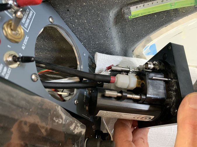
There are black flexible tubes to the Garmin G5 in the form of service loops so the unit can be removed, battery changed or whatever, without undoing a lot of hard lines.
I’ll need to get this whole system professionally checked for leaks annually. For now things seem to work.

